1. 41
3. PROCESS PARAMETERS
The data obtained in a uniaxial tensile test has limited use for metal forming calculations as
metal forming conditions are far different from those available in uniaxial tensile test.
Stress−strain characteristic are affected by two types of factors.
1. Factors related to deformation process
(i) amount of deformation (∈)
(ii) strain rate (∈)
(iii) operating temperature (t)
2. Factors not related to deformation process
(i) chemical composition and metallurgical structure
(ii) average grain diameter
(iii) pre strain history of materials.
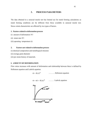
I. AMOUNT OF DEFORMATION
Flow stress increases with amount of deformation and relationship between these is defined by
Hollomon equation and Ludwik equation.
σ = K (t ) n ………. Hollomon equation
σ = σi + K (∈) n ……… Ludwik equation
2. 42
Fig. 1
n = 1 is valid for metals which are heavily deformed.
Larger the amount of deformation, greater will be value of flow stress.
Table 1
Typical values for k and ‘n’ at room temperature.
Material K(MPa) N
Aluminium
1100−0 180 0.2
2024−T4 690 0.17
6061−0 200 0.2
3. 43
Brass
70/30 annealed 900 0.5
85/15 cold rolled 580 0.33
copper, annealed steel 315 0.55
Low Carbon 530 0.25
4135 annealed 1015 0.18
4135 cold rolled 1100 0.14
304 stainless steel (annealed) 1275 0.45
410 stainless steel (annealed) 960 0.1
C 60 quenched/temnp 1600 0.1
Table 2
σ = C(∈) m
1. Strain hardening exponent ‘n’ is useful in determining the behaviour of materials during
many working operations.
2. When deformation exceeds abilities of a material to undergo uniform straining, strain get
localized and necking takes place. The strain hardening exponent is a measure of materials
abilities to distribute strain uniformly and resist localization of strain and thereby delays
necking.
4. 44
Materials which have a high work hardening exponent such as copper and brass (n
≥ 0.5) can be given a large plastic deformation move easily than those which have smaller
n, such as heat treat steel (n ≈ 0.15) . Materials having higher n value are desirable in wire
drawing.
3. ‘n’ represent limiting strain for uniform and homogenous deformation.
4. High value of 302 austenitic steel (n = 0.3) n is an indication of poor machinability. This is
because the cutting action of the tool causes strain hardening a head of the tool. Due to the
high ‘n’ value, this causes a large increase in strength and hardness. Thus the cutting tool is
always working against higher strength material, reaviring larger cutting forces.
5. In contrast, a high value is desirable for sheet formation, in which resistance to local
necking or reduction in sheet thickness is necessary. When a high ‘n’ value material begins
to neck, the deforming region rapidly strain hardens, causing subsequent plastic
deformation to occur in the surrounding softer metal. This produces a long diffusion neck.
In contrast, neaking in a material with a low value occurs move locally, causing failure at a
lower strain.
Fig. 2
Comments on Hollomon equation
1. It is found that the work hardening of many metals approximates to a parabolic form. For
annealed metals with cubic lattice, the stress−strain relation is well defined by Hollomon
5. 45
equation. For pre-worked materials, this equation gives less accurate results. The values of
stress are valid from yield point to maximum load point.
2. Strain hardening exponent for many metals range between 0 to 0.5. It is zero for non
hardening rigid plastic metals. The higher the value n, more pronounced is the strain
hardening of the material.
3. The stretching capacity [strain forming, deep drawing] of metals is related to its ability to
delay or resist necking. One measure of this resistance to neck is strain-hardening
exponent. The higher the value of ‘n’, larger is the uniform elongation and greater is
resistance to necking. A higher value of n improves the ability of metal to resist
localisation of strain in presence of stress gradient. This generates move uniform
distribution of strain and permits more effective utilisation of available metal.
A high value of n indicates good stretch formability and cold formed grade steels have n
value in the range of 0.22 to 0.5. On the other hand, hot rolled materials can have n values
as low as 0.1 and may undergo excessive thinning or fracture in severely strained region of
processing.
Time does not enter as a parameter and ordinarily, the deformation characteristics is taken
as independent of time.
4. A simple guide for calculating n for steels is
70
n =
σ 0 ( N / mm 2 )
5. Many a times, strain hardening exponent is considered as strain hardening rate, which is
not true.
σ = K (∈) n
log σ = log K + n log ∈
Taking derivative
dσ d∈ d∈
= 0 + n. = n
σ ∈ ∈
6. 46
∴ strain hardening rate
dσ σ
= n.
d∈ ∈
dσ σ
∴ strain hardening rate is not simply equal to n but equal to n . .
d∈ ∈
6. Limitations of Hollomon equation:
i. This equation is quite reliable when induced strain is greater than 0.04 but less than the
strain at which necking begins.
ii. Use of this equation to predict initial yield strength of the metal should be avoided.
Instead, a method such as offset should be used.
iii. Most metal working operations imparts strain far in excess of 0.04 and the exclusion of
the elastic and transition strain region leads to little error in this regard.
II. EFFECT OF TEMPERATURE ON FLOW STRESS
Flow stress in influenced by temperature. Flow stress decreases with increase in temperature.
Ductilities also increases with temperature. This characteristic is fully utilised in hot working
where large reduction are obtained at relatively lower flow stresses.
Fig. 3 : Effect of temperature on flow stress.
3. Strain rate
Strain rate (∈) does not influences flow stress in cold working. It is a significant factor in
determing flow stress in hot working. Flow stress increases with strain rate and dependence of
flow stress on strain rate increases with temperature.
7. 47
Fig. 4
log σ = m log ∈ + log c
σ = c (∈) m
where m = strain rate sensitivity exponent
c = strain rate strength constant
σ = c (∈) m
8. 48
As the temperature increases the slope of the curve increases. Thus the strength becomes move
and more sensitive to strain rate as temperature increases. Slope is relatively flat at room
temperature
m
Cold working upto 0.05
Hot working 0.05 to 0.4
Super plastic 0.3 to 0.85
High the value of m, more the capacity of the material to delay the necking and more stretching
is possible at elevated temperature before failure.
2. When strain rate is of high order, the stress−strain curve change as a function of strain
rate in accordance with equation
σ = C (∈) m
m = 0 stress is independent of strain rate
m = 0.2 common metals
= 0.4 to 0.9 superplastic metals
Fig, 5
The dependence of flow stress on strain rate increases with temperature.
Larger the value of m, more postponement of necking will be. The reason for this is that as soon
as necking starts in some region, the strain rate (∈) increases locally resulting in a rapid increase
9. 49
in the stress required to cause further deformation in that region. The deformation then shits to
other region of the material, where there is no necking. Here the strain rate and hence the stress
to cause deformation is smaller stainless steel, aluminium and titanium alloys exhibit
superplastic behaviour.
Principal effects of strain rate in metal forming: -
1. Flow stress of metal increases with strain rate, especially at temperatures above
recrystallisation temperature.
2. At higher strain rates, the temperature of workpiece increases abnormally as there is little
time available for heat transfer. It is adiabatic heating.
3. Lubrication at the tool-work interface improves as long as lubrication is maintained – At
higher strain rates there is possibility of breakage of lubrication film, resulting in poor
surface finish.
Deformation velocity of commercial equipments used in metal forming is much higher than
observed in tension test. For wire drawing at speed of 40 m/s result in strain rate of 10 5 s −1 .
However, there is a group of newer metal working processes which utilises velocities as high as
200 m/s to carry out forging, sheet forming, extrusion etc. They are known as High Velocity
Forming [HVF] and High Energy Rate Forming processes. These processes have strain rate
much higher than the conventional methods. For many materials elongation limit (upto fracture)
increases with strain rate, upto limit. Beyond this limit of strain rate ductility falls sharply, this
limit is called as critical strain rate.
At the other extreme of strain rate spectrum, there is superplastic forming. Materials having high
strain rate sensitivity index ‘m’ (0.3 <m ≤ 1) exhibits pronounced resistance
for necking. Superplasticity behaviour is observed when operating temperature is above 0.4 Tm
and strain rates are below 0.01 sec −1 .
• Very fine grain (grain size <10 µm)
• High operating temperature (T > 0.4 Tm)
• Very low strain rate ( ∈< 0.01 S −1 ).
10. 50
The chief advantages of superplasticity
(i) Very low How stress 5 – 30 MPa
(ii) Very large deformations can be obtained.
The effect of m on hot deformation behaviour is somewhat analogous to that of strain hardening
exponent for cold deformation. A high ‘m’ value causes a considerable increase in strength and
hardeness of the material at high strain rates, leading to a requirement for higher forming forces.
Alternatively, for high m materials a slow strain rate is necessary for forming. This can lead to
unacceptably long and often, uneconomical forming time. An important advantage of a high m
value, like a high n value is improved formability resulting from forming a diffuse neck rather
than a local neck.
A positive value of ‘m’ reduces localisation of strain and thus necking. A large and positive
value of ‘m’ opposes rapid localisation of strain and causes neck to be more diffused. In reverse
way, a negative value of ‘m’ promotes localisation of strain and thus generate severe strain
gradient. Thus both sign and magnitude of ‘m’ is important.
In sum a positive value of strain rate sensitivity index.
1. Higher stresses are required to form part at higher strain rates.
2. At a given forming rate, the material resists further deformations in regions that are being
strained more rapidly than adjacent region by increasing the flow stress in these regions.
This helps in distributing strain more uniformly.
In many forming operation, need for higher stress for deformation is not a major consideration
but ability to distribute strain uniformly is one. Generally, metal have value – 0. 01 to 0. 06.
Metals in superplastic region have high ‘m’ values, which is one to two orders higher than
typical steel. High ‘m’ and ‘n’ values is of little use in deep drawing as they strengthen wall as
well as flange which make it harder to draw.
Mean strain rate (∈m ) for various metals forming processes:
11. 51
1. For up setting and tension test
v
∈m =
v = cross head
h
velocity
h =
instantaneous height of the specimen.
2. For extrusion and wire drawing
2
6 V d 0 log R
∈m =
V = extrusion velocity
(d 3 − d 1 )
0
3
d 0 = billet diameter
d1 = extrusion diameter
R = extrusion ratio.
3. For rolling
V h
∈m =
× log 0 h 0 = thickness of slab before rolling
h h1
h 1 = thickness of slab after rolling.
Superplastic behaviour of metals and alloys
Conventioned metals and alloys exhibit elongation in the range of 10 to 60%. Some metals and
alloys exhibit very large deformations, more than 100% and even upto 3000% with out fracture.
This behaviour of metals is termed as superplastic behaviour. It has enabled the economical
production of large, complex shaped products with compound curves. Deep or complex shapes
can now be made as one piece [rather than joining /welding many pieces into a assembly], single
operation pressing rather than multistip conventional pressings. Precision is excellent and fine
details or surface texture can be reproduced accurately. Springback and residual stresses are non
existent and products have a fine, uniform grain size.
Main characteristics of superplastic behaviour are:
i. Very large deformations are obtained without fracture. It permits forming of metals as if
they are polymer or glass.
12. 52
ii. The other characteristics normally observed concurrently is substantial reduction in flow
stress. The flow stress is about 5 to 50% of the conventional method flow stress.
Following are requirements if the material is to exhibit superplstic behaviour:
1. The operating temperature should be more than the half of melting point.
T > 0.5 Tm Tm = melting point k.
2. Small and stable grain size. Grain size should be less than 10 µm. The presence of second
phase particles inhibit grain growth at high operating temperature. Further, the strength of
second phase should be similar to that of matrix to avoid excessive cavity formation.
3. Flow stress of superplastic material is very sensitive to the strain rates. High value of strain
rate sensitivity index is necessary. Strain rate sensitivity index should be in the range of
0.3 to 0.9
i.e. 0.3 < m < 0.9
4. Superplasticity is observed within specified range of strain rates. Ductility reduces
dramatically on either side strain rate range is 10 −5 to 10 −2 / Sec. of this range.
Superplastic deformation occurs predominantly by grain boundary sliding and grain
rearrangement. Both of these mechanisms require a large grain area and hence the need for a
small grain size. They are accommodated by grain boundary diffusion which is a temperature
activated process and hence the requirement for elevated temperature.
The strain rate sensitivity index (m) itself is function of strain rates and strain rate range should
be 10 −5 to 10 −2 / sec . Within this range of strain rate, m is sufficiently large for superplastic
behaviour of metal. It is observed that the high value of m is obtainable with fine grain
microstructure or m value increases with decrease in grain size. Such a fine grain structure is
easily obtained and maintained in eutectic and eutectoid alloys. For these materials different
microstructure/phases are formed simultaneously at subeutectic or subeutectoid temperatures and
13. 53
then precipitate in a fine dispersion. It is, however, demonstrated that superplastic behaviour is
not confined to these two phase structures, but even fine grained pure metals also exhibit the
same.
A characteristics feature of superplastic deformation is that large macroscopic elongations are
possible without significant elongation of individual grains. In superplstic alloy, grain boundary
sliding constitutes the greatest contribution to deformation in superplastic region.
Fig. 6 : Dependence of m on strain rate.
Superplastic alloys
Small and stable grain size is requirement for superplastic behaviour of metal and therefore not
all commercially available alloys are superplastic. Following alloy exhibit superplastic
behaviour.
Alloy Temperature ∈
m % elongation
Titanium
Ti – 6 Al – 4V 850 10 −3 0.75 750 – 1150
Ti – 6 Al – 4V- 2Ni 815 2 × 10 −4 0.85 720%
Aluminium
Al – 33 Cu 450 8 × 10 −4 0.8 400 – 100%
Zn 78% + 22% Al 240 C - 0.5
Al 67% + 33% Cu 480 C - 0.9
Cu 90 + 10% Al 500 - 0.5
14. 54
Advantages
1. Commercial development of superplastic materials has made it possible the production of
large, complex shaped products often in limited avantity economical. Deeper or complex
shaped can be made from one piece in a single operation rather than multistep conventional
pressing or multipiece assemblies.
2. Drastically deduced flow stress of the material.
3. Because of the low forming pressures, forming blocks can be used in place of die set and
hence tooling is relatively inexpensive.
4. It requires shorter production lead time.
5. Many applications of superplasticity eliminates a considerable number of subsequent
operations. The weight of the products can be reduced and there are fewer fastening holes.
These holes generally initials cracks on repeated loads.
6. Precision obtained is excellent and fine details are produced− products have fine and
uniform grain size.
Limitation
A major limitations to superplastic forming is the low forming rate that is required to maintain
superplastic forming, cycle time range from 2 min to 2 hours per part is too long compared to
several seconds that is typical of conventional press work. As a result, application tend to be
limited to low volume products such as those common to aerospace industry. By making
products larger and eliminating assembly operations, the weight of products can be reduced.
There are fewer fastening holes to initiate fatigue cracks, tooling and fabrication costs are
reduced.
15. 55
Strain hardening
Strain hardening is a phenomenon whereby the yield stress of a metal increases with increasing
deformation (strain). It occurs at low temperature, below recrystallisation temperature which is
about 0.5 Tm (Tm is melting point temperature K). This applies to forming temperatures that are
so low that thermally activated processes play no significant role. Strain hardening results in
higher forming force and forming energy requirement, thus increasing load/stresses acting on the
tool. Strain hardening increases strength and hardness but cause decrease in ductility and
therefore in many cases, annealing become necessary to restore ductility and formability to
obtain the required deformation. To negate the effect of strain hardening, forming can be carried
out at elevated temperatures, the accuracy and surface quality obtained would be inferior to the
one obtained in cold forming.
Besides these undesirable side effects of strain hardening there is an increase in the strength
values of the finished components through forming which is very desirable. Strain hardening
can be used for practically all metals and alloys to increase hardness and strength. The increased
strength permits the use of materials with lower initial strength compared to components
produced by machining. Moreover, in many cases heat treatment (costly and time consuming) is
unnecessary because of strain hardening.
Strain, hardening is a result of a large number of dislocations participating simultaneously.
During metal forming the dislocation density increases by several order from 10 7 to 1012 / cm 2 .
By this zones of higher dislocation density emerge, which represent a hindrance for moving
dislocations. Presence of dislocations lowers the shear stress required to cause slip. But
dislocations can:
(i) become entangled and interfere with each other.
(ii) be impeded by barriers, such as grain boundaries and inclusions in the material.
As dislocation density increases, the stress required for moving dislocation increases due to
interfering effect of stress fields surrounding the dislocations. Entanglement and impediments
increase the shear stress required for slip. The effect is an increase in shear stress that causes an
16. 56
increase in the overall strength of the metal, known as strain hardening or work hardening. This
phenomenon forms basis for work hardening, described by means of equation:
The shear stress τ to move a dislocation increases with increasing dislocation density e,
according to the following equation.
τ = τ0 + A ρ
where τ 0 = base stress to move the dislocation in the crystal in the absence of other dislocations.
A = constant
This equation describes the work hardening behaviour. For a soft crystal, the CRSS (critically
resolved shear stress) for initiation of plastic deformation is typically 0.5 N / mm 2 .
10
A = 0.01 N/mm = N / mm
1000
low dislocation density = 10 4 / mm 2
CRSS for annealed crystal = T0 = 0.5
1
= 0.5 N / mm 2 + × 10 4
100
= 1.5 N/mm 2
heavily cold worked, the dislocation density increases to 10 8 / mm 2
1
= 0.5 + × 10 8
100
= 100 N / mm 2 .
Strain hardening depends on :
1. Lattice structure. Strain hardening rate is greater for cubic crystal.
17. 57
(i) Strain hardening rate in FCC metals is affected more than for HCP crystals by stacking
fault energy. Therefore, copper, nickel, austenitic steel harden more rapidly than
aluminium.
(ii) HCP (Hexagonal close packed) metals subjected to “twinning” and strain hardening rate is
much rapid as there is only one plane for easy glide.
(2) Strain hardening rate increases with complexity of structure − impurities, grain size, second
phase particles etc. Therefore, final strength of the cold worked solid solution alloy is
always greater than that of pure metal cold worked to the same extent.
Strain hardening capacity
Two measures of strain hardening capacity
yield strength 240
i. ratio of = = (for ms) = higher the ratio.
ultimate strength 380
ii. uniform elongation eu which is the elongation at max load.
n = log (1 + eu)
value of ‘n’ is highest when the material is normalised. It is lowered by cold working. A
typical low carbon steel has ‘n’ value 0.2 to 0.22. A value of 0.25 is considered high for
these steels while those below 0.18 are considered to have low ductility and poor strain
hardening capacity.
Strain hardening is an important industrial process used for strengthening and hardening metals
[Cu, Al] or their alloys which do not respond to heat treatment process. Of course, the product
must not be used at temperature that will anneal the metals.
Strain hardening has important place in industry.
18. 58
i. It alters the properties of metal. Cold working improves strength and hardness of metal, but
reduces elongation.
Fig. 7
Cold work reduces the amount of plastic deformation that a metal can undergo
subsequently during shaping operation. The hardened, less ductile, cold worked metal
require more power for further working and is subjected to cracking. Therefore cold work
anneal cycles are used to assist production i.e. formation limit is extended through
annealing. The loss of ductilities has useful side effect − improvement in machinability by
25% in low−medium carbon steel. With less ductility, chips break move readily thus
facilitating cutting operation. Cold work stock is used for machining screw stock.
ii. The preferential orientation of second phase particles and structural discontinuities [voids,
inclusions, segregations] in the principal direction of deformation give rise to mechanical
fibering. A important consequence of mechanical fibering is that mechanical properties in
different directions. In general, tensile strength, ductility,
fatigue strength is more in longitudinal direction than transverse. But shear strength is
greater in transverse direction.
FRICTION IN METALS
Friction is defined as the resistance to relative motion between two bodies in contact, under a
normal load. Friction plays an important role in metalworking and manufacturing processes
because of the relative motion and forces that are always present on tools, dies, and workpieces.
19. 59
Friction dissipates energy, thus generating heat, which can have detrimental effects on an
operation. Furthermore, because friction impedes free movement at interfaces, it can
significantly affect the flow and deformation of materials in metalworking processes. On the
other hand, friction is not always undesirable; without friction, for example, it would be
impossible to roll metals, clamp workpieces on machines, or hold drill bits in chucks.
Friction plays a great role in all engineering applications whenever solid surfaces are in sliding
contact with each other. This is particularly true in metal working processes where the sliding
pair of surfaces are metals and where plastic deformation of the softer of two metals usually
takes place. Friction conditions between the deforming tool and workpiece in metal working of
greatest importance as it decides force required and mode of deformation, properties of the
finished specimen, resulting surface finish etc.
The friction stress, τ is measured in force per unit area. The surface area of contact is a
boundary of the deformed metal.
I. Coulomb’s Friction Law
F N
F=µ×N ⇒ =µ×
A A
T= µ × P
F = Frictional force
A = Apparent area of contact
Fig. 8
20. 60
The tangential stress, Tat any point on that surface is proportional to the pressure p between the
two bodies and is directly in opposite direction to the relative motion between these bodies. The
coefficient of friction ‘µ’ is taken as constant for given die and the workpiece (under constant
surface and temperature conditions) and is said to be independent of the velocity, applied load,
and area of contact.
Fig. 9
µP > k
It is expected that this relation is sufficient to describe the conditions until the product of µ and P
(µP) becomes higher than the yield stress in pure shear (k) of the material. The material will then
stick to the tool and yielding takes place in the interior of the material. Modern theory of friction
is based on premise that flat surface is not flat but consists of numerous peaks and valleys.
21. 61
Apparent Actual surface
Fig. 10
A commonly accepted theory of friction is the adhesion theory, developed by F.P. Bowden
(1903 − 1968) and D. Tabor (1913 −). The theory is based on the observation that two clean and
dry surfaces, regardless of how smooth they are, contact each other (junction) at only a fraction
of their apparent area of contact (Fig. 8). The maximum slope of the hills on these surfaces
ranges typically between 5 and 15 .
In such a situation, the normal (contact) load, N, is supported by the minute asperities (small
projections from the surface) that are in con tact with each other. The normal stresses at these
asperities are, therefore, high; this causes plastic deformation at the junctions. Their contact
creates an adhesive bond: the asperities form microwelds. Cold pressure welding is based on this
principle.
Sliding motion between two bodies which have such an interface is possible only if a tangential
force is applied. This tangential force is the force required to shear the junctions; it is called the
friction force, F. The ratio of F to N (see Fig. 8) is the coefficient of friction, µ.
22. 62
Fig. 11: Schematic illustration of the interface of two bodies in contact, showing real areas of
contact at the asperities. In engineering surfaces, the ratio of the apparent to real areas of
contact can be as high as 4 − 5 orders of magnitude.
In addition to the force required to break these junctions by shearing, a plowing (or ploughing)
force can also be present if one surface scratches the other (abrasive action). This force can
contribute significantly to friction at the interface. Plowing may (a) cause displacement of the
material and/or (b) produce small chips or slivers, as in cutting and abrasive processes.
Depending on material and processes involved, coefficients of friction in manufacturing vary
significantly, as is obvious in Table 1.
Table 1: Range of Coefficients of Friction in Metalworking Processes
Coefficient of friction (µ)
Process Cold Hot
Rolling 0.05 − 0.1 0.2 − 0.7
Forging 0.05 − 0.1 0.1 − 0.2
Drawing 0.03 − 0.1 −
Sheet−metal forming 0.05 − 0.1 0.1 − 0.2
Machining 0.5 − 2 −
Almost all of the energy dissipated into heat (a small fraction becomes stored energy in the
plastically deformed regions; raising the interface temperature. The temperature increases with
friction, sliding speed, decreasing thermal conductivity, and decreasing specific heat of the
sliding materials. The interface temperature may be high enough to soften and even melt the
surfaces, and sometimes to cause microstructural changes.
23. 63
Temperatures also affects the viscosity and other properties of lubricants, causing their
breakdown. Note, for example, how butter and oil burn and are degraded when temperatures are
excessive. These results, in turn, adversely affect the operations involved, and cause surface to
the object.
When two surfaces are in touch, sufficient contact is established to support the applied load.
A = Apparent area of contact After application of
load
Ar = real area of contact
Fig. 12
Ar, real area of contact increases with increases in load.
N
Ar = σ 0 = yield strength of weaker material in contact.
σ0
Large stresses and plastic deformation causes the tear off upper contaminated layers present on
the surfaces. Then the real materials come in contact. This results in welding of the asperity
junction and the sliding of one body above the other will be possible only after these asperity
junctions are sheared:
Force required to shear Fs = T × Ar T = shear strength of weak
Fs τ × Ar T
µ= = =
N σ 0 × Ar σ0
T = µ σ0
24. 64
From this, µ depends only on material in contact. For better results, T and σ 0 should be taken for
T
alloy formed at the junction due to heavy cold work and welding. But µ = is valid only when
σ0
Ar <<< A 0 . As Ar attains the value of A (apparent area), the force required to slide will not
increase even if N is increased. Under such situation, mechanism other than welding of asperity
junctions become active making friction phenomenon quite complex. One such mechanism is
locking of asperities.
Resistance to sliding motion is due to:
i. The force necessary to plough the peaks of harder material through softer material.
ii. The force required to break welding weldaments.
Ar < A
Fig. 13
2. When real area of contact approximates apparent area, movement w.r.t. each other
continues but due to subsurface shearing in softer and weaker material. The frictional
force, then, equals the shear strength of the material.
25. 65
Fig. 14
Such type of friction is called “sticking friction”.
σ
Ts = 0 (As per Von miser) σ 0 = yield strength of softer material [Aluminium].
3
T =µP P = normal pressure.
A very low value of ‘µ ’ = 0.05 is possible with highly polished tool surface and flood lubrication
with soluble oils. ‘µ’ between 0.05 to 0.15 are usually found in cold working operations such as
wire drawing, tube drawing and extrusion − while rolling thin strips
with mirror finish rolls, a value of 0.05 is common. However, in cold rolling with good
lubrication µ can range between 0.07 − 0.15. In hot rolling, presence of scale increases the
value of ‘µ’and depends on rolling temperature. A value of 0.4 is quite common in rolling at
400 C.
Ar
Amonton’s law is a good approximation for ordinary sliding where << 1.
Aa
26. 66
But in metal forming, areal area of contact approximates apparent area of contact.
Fig. 15
Zone I:
Ar
Plastic deformation is confined to asperties only and thus << 1. Amonton’s law is obeyed.
Aa
Zone II:
Ar increases with deformation but ‘µ’ decreased.
Zone III:
T does not vary with normal pressure and become independent of normal stress.
Sliding Friction Sticking Friction
1. One surface slides over the other 1. In sticking friction the metal surface
and friction exist there is no welding
adjacent to the tool surface does not slide,
of two surfaces at the contact
instead it moves due to shearing.
interface.
Fig.
SubSurface shearing occur in aluminium.
27. 67
2. The definition of coefficient of 2. Under such conditions the coulomb’s law
friction implies that the frictional ceases to apply and the magnitude of shear
force is directly proportional to stress is controlled by the shear strength of
normal force and there must be the work material. For the case of sticking
relative movement between the friction the frictional stress
workpiece and die surfaces. σ
Interfaces at which these conditions
T= 0
2
exists undergo sliding friction.
σ 0 = yield stress of the material in tension.
It is valid when Due to high interface pressure P, the frictional
µ P << k shear stress Ti = µP is greater than shear
stress required for shearing the workpiece
(workpiece has lower shear strength
compared to die metal). If this occurs, less
tangential force is required for metal to shear
within the body of the workpiece than for the
workpiece to move relative to the die. This is
referred as sticking friction, through no actual
sticking together of the die and workpiece
necessarily occur. Ti = µP > k (shear
strength of workpiece) when this inequality is
satisfied, ‘µ’, the coefficient of friction
becomes meaningless. Hence sticking
friction represents an upper limit to the
interface frictional stresses.
The interface pressure developed in the most
metal working process is at least equal to
uniaxial yield stress and may appreciably
exceed K (shear strength). As K is
K
independent of applied pressure, µ = is
σ0
not correct to describe sticking friction, leads
to misinterpretation.
3. Usually present in cold working. 3. Usually present in hot working.
Sticking deformation is undesirable.
i. Deformation with sticking friction requires greater energy.
28. 68
ii. Because localised internal shearing of the workpiece occurs, results in less deformation
homogeneity compared to sliding friction.
Q. Show that the maximum meaningful friction coefficient is 0.5.
Soln:
The interface shear stress is τ i = µP. The interface pressure P is the same as the normal
interface stress σ 0 . ∴τ i = µ σ 0 .
From the Tresca or maximum shear stress yield criterion, τ i max ≈ 0.5 σ 0 . The internal
shear stress τ i cannot exceed τ i max, because when τ i = τ i max yielding of the workpiece
in shear will occurs. Therefore τ i = µP = 0.5 σ 0 = τ i max; the maximum µ = 0.5. A
coefficient of friction above 0.5 is not attainable as the shearing of the workpiece will have
occurred.
Effect of friction in metal forming:
1. Force required for deformation increases with friction.
1 + B B
σ x = σ0
B [1 − R ]
4µL
Pt = σ 0 log R +
Ram travel
d0
1. Direct extrusion
2. Indirect extrusion
3. Hydrostatic extrusion
Fig. 16
29. 69
Fig. 17
In extrusion, friction exists between billet and die and between billet and container.
Friction between die and container is eliminated in indirect extrusion but between die and
billet exists. In hydrostatic extrusion, friction is eliminated altogether and lower amount of
force is required for extrusion.
2. Excess load capacity is provided and load perse is not important aspect from practical point
of view. Effective lubrication decreases the load requirement but it also serves other more
important functions.
i. prevention of pickup:
If too much surface contact occurs, metal pickup on the tooling can damage product
finish and size.
ii. minimizes tool wear and thus better control over size and lower maintenance cost.
iii. Frictional energy is converted into heat and raises the temperature of workpiece. To
keep the temperature at lower level, extrusion velocity is reduced in hot extrusion of
M.S.
3. Friction plays positive role in rolling. Rolling is not possible without adequate friction
between the rolls and bloom−billet.
For rolling µ ≥ tan α α = angle of bite.
1 1
i. ∆h max = De 1 − = De 1 −
1 + µ2 1 + (tan α) 2
30. 70
ii. ∆h min = 0.035 µ R σ
σµ R
=
12.8
α = 5 for cold rolling
= 20 − 30 for hot rolling.
4. Proper distribution of friction improves the deformation process.
i. Deep drawing
The coefficient of friction around punch corner should be high and that around die
corner should be low. It prevents thinning of the sheet metal.
ii. Tube drawing
If the friction between tube and mandrel is high, then drawing load is shared by the
mandrel and thereby reducing the stress in the tube wall. This allows for large
reduction ratios.
Fig. 18
µ − µ2
B= 1
tan α
31. 71
5. Friction causes more wastage of material especially in extrusion. The dead zone formed in
direct extrusion is result of friction and redundant work. It causes 20−30 % wastage of
material which is quite large compared to indirect extrusion where friction between
container and billet is eliminated.
Lubrication
The surfaces of tools, dies and workpieces are subjected to
(i) forces and contact pressure, ranging from very values multiples of the yield stress of the
workpiece material.
(ii) relative speeds, from very low to very high.
(iii) temperatures, which range from ambient to melting.
Metal working fluids should be applied to reduce friction and wear effectively working
temperature. Lubrication is the process of applying these fluids and solids. There are four types
of lubrication:
Lubrication mechanism
1. Boundary 2. Thick Film 3. Thin Film 4. Mixed
Lubrication (full film lubrication) Lubrication
Lubrication
Fig.
Fig. Fig.
A thin layer of low shear • Completely prevent • Some metal to metal
strength material adheres at metal to metal contact. contact occurs.
surface interface. Adherence
may be physical or chemical
[Sulphur, chlorine] or both.
• film thickness is about 10 • film thickness is about 5
Ra (Ra = surface Ra
roughness)
32. 72
(a) Thick film
(b) Thin film
(c) Mixed
(d) Boundary
Fig. 19: Types of lubrication generally occurring in metalworking operations.
a. In thick− film lubrication, the two mating surfaces are completely separated by a fluid film
as in hydrodynamic lubrication, and lubricant viscosity is the important factor. Such films
can develop in some regions of the workpiece in high−speed operations, and can also
develop from high−viscocity lubricants that become trapped at die−workpiece interfaces.
The film thickness is 10 Ra.
There is no metal to metal contact and therefore no wear of parts. The coefficient of friction is
between 0.001 to 0.02 and depends on viscosity of lubricant and contact pressure. Coefficient of
friction increases with normal pressure [double with every increase in pressure by 35 MPa] and
decreases with increase in temperature [every rise of temperature by 15 C decreases it to half].
33. 73
Conditions favourable for thick film lubrication are somewhat rare in metal working but
they do occur at higher sliding speed. High speed wire drawing and rolling are best
examples this.
A thick lubricant film results in a dull, grainy surface appearance on the workpiece,
whereby the degree of roughness depends on grain size (Fig. 19). In operations such as
coining and precision forging, trapped lubricant are undesirable because they prevent
accurate shape generation.
b. Thin film lubrication
As the load between the die and workpiece increases or as the speed and the
viscosity of the metal working fluid decrease, the lubricant film becomes thinner (thin film
lubrication). The film thickness decreases to 3 to 5 Ra. This causes some metal to metal
contact and raises the friction at the sliding interfaces and result in slight wear.
c. Mixed lubrication
In most liquid lubricated metal working operations. Some asperity contact is unavoidable.
A significant part of the load is carried by the metal to metal contact and rest is carried
pockets of liquid in the valleys of the asperities. This mixed film lubrication is common in
metal working. Boundary lubricants with extreme pressure (EP) are added to the fluid at
the points of metal contact.
d. Boundary lubrication
In boundary lubrication, the load is supported by contacting surfaces covered with a
boundary film of lubricant. These are thin organic films physically adhered to the metal
surfaces or chemically adsorbed on the metal surface, thus preventing direct metal to
metal contact of the two bodies and hence reducing wear. The boundary lubricants are
typically polar substances, natural oils, fats, fatty acids, esters or
soaps. These films are firmly adhered to the metallic surfaces and have lower shear
strength, thereby sliding surfaces takes place easily.
34. 74
Solid lubrication
Product resulting from the reaction of liquid lubricant and parent metal can be termed as solid
lubricant because solid phase formed of it is effective as lubricant.
Sometimes interposing film of molybdenum disulphide, graphite, teflon is used as lubricant.
These films have lower shear strength which is temperature and pressure dependent. Boundary
film forms rapidly and as the film thickness decreases, metal to metal contact occurs. Depending
on the boundary film shear strength and its thickness, the coefficient of friction varies between
0.1 to 0.4.
Boundary films can break as a result of:
i. desorption caused by high temperatures at the sliding interfaces
ii. being rubbed off during sliding.
Deprived of this protective film, the metal surfaces may then wear and score severely.
Other Considerations
The valleys in the surface roughness of the contacting bodies can serve as local reservoirs or
pockets for lubricants, thereby supporting a substantial portion of the load. The workpiece, not
the die, should have the rougher surface; otherwise, the rougher and harder die surface, acting as
a file, may damage the workpiece surface. The recommended surface roughness on most dies is
about 0.4 µm .
The overall geometry of interacting bodies is also an important consideration in ensuring proper
lubrication. The movement of the workpiece into the deformation zone, as during
wire drawing, extrusion, and rolling, should allow a supply of lubricant to be carried into the
die−workpiece interface. With proper selection of process parameters, a relatively thick lubricant
film can be entrained and maintained.
METALWORKING FLUIDS
The functions of a metalworking fluid are to:
a. reduce friction, thus reducing force and energy requirements, and temperature rise.
b. reduce wear, seizure, and galling.
35. 75
c. improve material flow in tools, dies, and molds.
d. act as a thermal barrier between the workpiece and tool and die surfaces, thus preventing
workpiece cooling in hot−working processes.
e. act as a release or parting agent, a substance which helps in the removal or ejection of
parts from dies and molds.
Several types of metalworking fluids are now available which fulfill these requirements and
which have diverse chemistries, properties, and characteristics. This section describes the general
properties of the most commonly used lubricants.
General properties of most commonly used lubricants
Oils have high film strength on the surface of the metal and it is effective in reducing friction and
wear. Oils have lower thermal conductivity and specific heat. Thus they are not effective in
conductivity away the heat generated by friction and plastic deformation in metal forming
operations. Oils are difficult to remove from component surfaces that are subsequently be
painted or welded, and they are difficult to dispose off. The source of oils are mineral
(petroleum), animal, vegetable and fish−oils may be compounded with variety of additives or
with other oils to impart special properties.
Metal working oils are blended with several additives. Important additives are sulphur, chlorine,
and phosphorus known as EP [Extreme Pressure] additives and used singly or in combination,
they react chemically with metal surfaces and forms adherent films of metallic sulphides and
chlorides. These films have lower shear− strength and good antiweld properties and thus
effectively reduce friction and wear. While EP additives are important in boundary lubrication,
these lubricant attack the cobalt binder in tungsten carbide tools and dies, causing increase in
their roughness and integrity.
Emulsions [or water soluble fluids] are two types: direct and indirect. In direct emulsions,
mineral oil is dispersed in water as very small droplets. Direct emulsions are important fluids
because the presence of water gives them high cooling capacity and useful in high speed cutting.
Oils maintain high film strength on the surface of a metal, as we can observe when trying to
clean an oil surface. Although they are very effective in the reduction of friction and wear, oils
36. 76
have low thermal conductivity and low specific heat. Consequently, they do not effectively
conduct away the heat generated by friction and plastic deformation. In addition, it is difficult
and costly to remove oils from component surfaces that are to be painted or welded, and it is
difficult to dispose of them.
The sources of oils can be mineral (petroleum), animal, vegetable, or fish. Oils may be
compounded with any number of additives or with other oils; this process is used to change such
properties as viscosity−temperature behavior and surface tension, heat resistance, and boundary
layer characteristics. Mineral (hydrocarbon) oils with or without additives, used undiluted, are
known as neat oils.
Oils can be contaminated by the lubricants used for the slideways and various components of the
machine tools and metalworing machinery. These oils have different characteristics than those
used for the process itself, and thus can have adverse effects. When present in the metalworking
fluid itself, these oils are known as tramp oil.
Emulsions
An emulsion is a mixture of two immiscible liquids, usually of oil and water in various
proportions, along with additives. Emulsifiers are substances that prevent the dispersed droplets
in a mixture from joining together (hence the term immiscible).
Milky in appearance, emulsions are also known as water− soluble oils or water− base coolants,
and are of two types: direct and indirect. In a direct emulsion, mineral oil is dispersed in water in
the form of very small droplets. In an indirect emulsion, water droplets are dispersed in the oil.
Direct emulsions are important fluids because the presence of water gives them high cooling
capacity. They are particularly effective high−speed machining where temperature rise has
detrimental effects on tool life, the surface integrity of workpieces, and the dimensional accuracy
of parts.
Synthetic and Semisynthetic Solutions
Synthetic solutions are chemical fluids that contain inorganic and other chemicals dissolved in
water; they do not contain any mineral oils. Various chemical agents are added to a particular
37. 77
solution to impart different properties. Semisynthetic solutions are basically synthetic solutions
to which small amounts of emulsifiable oils have been added.
Soaps, Greases, and Waxes
Soaps are typically reaction products of sodium or potassium salts with fatty acids. Alkali soaps
are soluble in water, but other metal soaps are generally insoluble. Soaps are effective boundary
lubricants and can also form thick film layers at die−workpiece interfaces, particularly when
applied on conversion coatings for cold metalworking applications.
Greases are solid or semisolid lubricants and generally consist of soaps, mineral oil, and various
additives. They are highly viscous and adhere well to metal surfaces. Although used extensively
in machinery, greases are of limited use in manufacturing processes.
Waxes may be of animal or plant (paraffin) origin; compared to greases, they are less “greasy”
and are more brittle. Waxes are of limited use in metalworking operations, except as lubricants
for copper and, as chlorinated paraffin, as lubricants for stainless steels and high−temperature
alloys.
Additives
Metalworking fluids are usually blended with various additives, such as the following:
a. oxidation inhibitors.
b. rust−preventing agents.
c. foam inhibitors.
d. wetting agents.
e. odor−controlling agents.
f. antiseptics.
Sulfur, chlorine, and phosphorus are important oil additives. Known as extreme− pressure (EP)
additives and used singly or in combination, they react chemically with metal surfaces and form
adherent surface films of metallic sulfides and chlorides.
38. 78
These films have low shear strength and good anti−weld properties and, thus, effectively reduce
friction and wear. On the other hand, they may preferentially attack the cobalt binder in tungsten
carbide tools and dies (selective leaching), causing in the surface roughness and integrity of
tools.
SOLID LUBRICANTS
Because of their unique properties and characteristics, several solid materials are used as
lubricants in manufacturing operations. Described below are four of the most commonly used
solid lubricants.
Graphite
Graphite is weak is shear along its basal planes and thus has a low coefficient of friction in that
direction. It can be effective solid lubricant, particularly at elevated temperatures.
However, friction is low only in the presence of air or moisture. In a vacuum or an inert gas
atmosphere, friction is very high; in that, graphite can be abrasive in these situations. We can
apply graphite either by rubbing it on surfaces or by making it part of a colloidal (dispersion of
small particles) suspension in a liquid carrier such as water, oil, or an alcohol.
There is a more recent development in carbon called fullerenes or Buckyballs. These are carbon
molecules in the shape of soccer balls. When placed between sliding surfaces, these molecules
act like tiny ball bearings. They perform well as solid lubricants, and are particularly effective in
aerospace applications as bearings.
Molybdenum Disulfide
This is a widely used lamellar solid lubricant; it is somewhat similar in appearance to graphite.
However, unlike graphite, it has a high friction coefficient in ambient environment. Oils are
commonly used as a carriers for molybdenum disulphide and are used as lubricant at room
temperature. Molybdenum disulfide can be rubbed onto the surfaces of a workpiece.
39. 79
Metallic and Polymeric Films
Because of their low strength, thin layers of soft metals and polymer coatings are also used as
solid lubricants. Suitable metals include lead, indium, cadmium, tin, silver, polymers such as
PTFE (Teflon) polyethylene, and methacrylates. However, these coatings have limited
applications because of their lack of strength under high contact stresses and at elevated
temperatures.
Soft metals are also used to coat high−strength metals such as steels, stainless steels, and
high−temperature alloys. Copper or tin, for example, is chemically deposited on the surface of
the metal before it is processed. If the oxide of a particular metal has low friction and is
sufficiently thin, the oxide layer can serve as a solid lubricant, particularly at elevated
temperatures.
Glasses
Although it is a solid material, glass become viscous at elevated temperatures and, hence, can
serve as a liquid lubricant. Viscosity is a function of temperature, but not of pressure, and
depends on the type of glass. Poor thermal conductivity also makes glass attractive, since it acts
as a thermal barrier between hot workpieces and relatively cool dies. Glass lubrication is
typically used in such applications as hot extrusion and forging.
CONVERSION COATINGS
Lubricants may not always adhere properly to workpiece surfaces, particularly under high
normal and shearing stresses. This property has the greatness effects in forging, extrusion, and
wire drawing of steels, stainless steels, and high−temperature alloys.
For these applications, the workpiece surfaces are first transformed through chemical reaction
with acids (hence the term conversion). The reaction leaves a somewhat rough and spongy
surface, which acts as a carrier for the lubricant. After treatment, any excess acid from the
surface is removed using borax or lime. A liquid lubricant, such as a soap,
is then applied to the surface. The lubricant film adheres to the surface and cannot be scraped off
easily.
40. 80
Zinc phosphate conversion coatings are often used on carbon and low−alloy steels. Oxalate
coatings are used for stainless steels and high−temperature alloys.
Friction and lubrication in rolling
The friction between the roll and the metal surface is of great importance. Frictional force is
required to pull the metal into the rolls. A large fraction of rolling load comes from the frictional
forces. High friction results in high rolling load, a steep friction hill and great tendency for edge
cracking. The friction varies from point to point along contact arc of the rolls. However, it is
very difficult to measure this variation in µ.
i. For cold rolling with lubricant µ varies from about 0.05 to 0.1.
ii. But for cold rolling friction coefficient from 0.2 upto the sticking conditions are common
[0.5 to 0.6].
Lubrication in hot rolling
1. Hot rolling of ferrous alloys is usually carried out without lubricant, although graphite may
be used, waterbased solution are used to cool the rolls and break up the scale on rolled
material. Nonferrous alloys are hot rolled with variety of compounded oils, emulsions and
fatty acids.
2. Cold rolling is carried out with water soluble oils or low viscosity lubricants such as
mineral oils, emulsions, paraffins and fatty oils.
3. Heating medium used in heat treating billets and slabs also act as lubricant. e.g. residual
salts from molten salt baths.
Lubrication in forging
Forging
1. Lubricants greatly influence friction, wear, force required and metal flow in the cavities.
They also act as a thermal barrier between the hot workpiece and relatively cool dies,
slowing the rate of cooling of the workpiece and improves the metal flow.
2. It acts as a parting agent, that is, one which inhibits the forging from sticking to the dies
and helps in its release from the die.
41. 81
3. For hot forging graphite, MoS 2 , and sometimes glass are used as lubricant. In hot forging,
the lubricant is usually applied directly to the dies.
4. For cold forging, mineral oils and soaps are commonly used as lubricants, applied after
conversion coatings of the blanks. In cold forging lubricant is directly applied to the WP.
5. The method of application and uniformity of the lubricant’s thickness blank is important.
HOT WORKING
Temperature of work material is resultant of following contributing factors:
1. Initial temperature of work and toolings.
2. Heat generated due to plastic deformation which is proportional to strain induced.
3. Heat generation due to friction at work−tool interface
4. Heat transfer from work material to tool and surrounding.
• Effect of temperature on metal forming processes:
1. Flow stress decreases with increase in work material temperature and therefore power
required deformation decreases. For this reason, hot working is used for
primary forming processes [rolling, extrusion, forging] where primary objective is to reduce
cross sectional area and refine grain size.
2. High operating temperature increases the deformation limit before fracture. True
strain of fracture of tungsten is increased from 1% at room temperature is 55% at 1000°C.
Very large reductions are possible at elevated temperatures because recovery process neutralises
the strain hardening effect of deformation.
∈1 , ∈2 , ∈3 are limiting strain at T3 , T2
and T1 temp.
∈3 > ∈2 > ∈1
T1 > T2 > T3
42. 82
Fig. 20
Hot working refers to deformation carried out under conditions of temperature and strain rate
such that recovery process occurs substantially and is predominant over the strain hardening,
thereby neutralising the effect of the later.
It is important to note that distinction between cold working and hot working does not depends
on any arbitrary temperature of deformation. Hot working is usually carried out at temperature
above recrystallisation temperature and approx. equals to.
0.6 Tm where Tm = melting point temperature at in K
Typically hot working temperature range
Material temperature °C
M.S. 900−1200
Aluminium 350−450
zinc, lead, Tin room temperature
Hot working temperature is high for commercial metals, but lead, tin, zinc recrystallise rapidly at
even room temperature and therefore working of these metals even at room temperature
constitutes hot working. In contrast, working of tungsten even at 1100°C, a hot working
temperature for steel, constitutes cold working because this high melting point metal has
recrystallisation temperature above this working temperature.
Recrystallisation Temperature
Recrystallisation does not occur unless the degree of cold work is sufficient and temperature is
sufficiently high. The minimum degree of cold work necessary for recrystallisation to occur is
called the critical degree of cold work. This is of the order of 2 to 3% for most of the metals land
alloys. The temperature at which a metal or alloy with normal degree of cold work completely
(i.e. 95 % or above) recrystalizes in a reasonable period (usually 1 hour) is called as the
recrystallisation temperature of metal. Recrystalisation temperature of a metal is dependent on
following factors:
43. 83
1. Degree of cold work
Recrystallisation is a process of nucleation and formation crystals. Deformed grains have more
free energy than undeformed one. The free energy difference between the cold worked
deformed crystals and the undeformed crystals is driving force behind recrystallization.
Therefore, applied deformation prior to recrystallization should be more than the crystal degree
of cold work. Further, the deformed grains and grain boundaries provide preferred sites for
nucleation. Larger the degree of cold work, lower is recrystalisation temperature. For example,
Amount of cold work Recrystallization temp time
20 % 3200 C 1 hour
60 % 2800 C 1 hour
2. Melting Point
Higher the melting point, higher is the recrystallisation temperature. It has been observed that
the recrystallisation temperature of most of metals and alloys are in the range of 0.4 to 0.6 of
their melting point temperatures in degree kelvin
Tcr = 0.5 Tm 0K , where Tm = melting point temperature in Kelvin.
Metal Recrystallization Melting point 0 C Re crystallization temp K
=
temperature melting po int K
Tin Below Room Temp 232 0.6
Lead Below Room Temp 327 0.5
Zinc Below Room Temp 419 0.43
Aluminium 150 660 0.45
Magnesium 200 650 0.51
Silver 200 960 0.38
Gold 200 1063 0.41
Copper 200 1083 0.35
Iron/Steel 450 1539 0.40
Platinum 450 1760 0.35
Nickel 600 1452 0.51
Tungsten 1200 3410 0.40
3. Purity of metal
Presence of soluble impurities or addition of small amount of soluble alloying elements raise the
recrystallisation temperature.
44. 84
(i) Six nine (99.9999 %) pure aluminium has recrystallization temperature below room
temperature and therefore cannot be strain hardened at room temperature. But
commercially pure aluminium has recrystallization temperature of 150 0C.
(ii) Recrystallization temperature of commercial purity copper is 150 0C but addition of 0.5 %
impurity of arsenic raises recrystallization temperature above 500 0C. Therefore, arsenic
copper is used for high temperature applications such as boiler tubes.
4. Grain size
Finer the original grain size, lower is the recrystallization temperature.
5. Heating time
It has little influence on recrystallization temperature. Recrystallization temperature is far more
important than recrystallisation time. One expects such results as flux of atoms is proportional to
diffusivity which in turn is strongly dependent on temperature.
Time and temperature required for recrystallization of 75 % cold worked aluminium alloy.
Time Temperature
1 minutes 350 0C
60 minutes 300 0C
40 days 250 0C
The effect of degree of cold work on recrystallized grain size.
45. 85
Fig. 21
The grain size of the material obtained at the end of recrystallisation depends temperature of
heating, time, degree of prior cold work and level of impurities. Lower temperature of heating
(above Tcr), higher degree of prior cold work and insoluble and fine impurity particles give
smaller grain size.
• LIMITS OF TEMPERATURE
1. The lower limit of temperature for hot working is the lower temperature for hot working is
the lowest temperature at which recrystallisation rate is rapid enough to eliminate strain
hardening effect. This temperature depends on − (i) the amount of prior deformation. The
greater the amount of prior deformation, lower is the recrystallisation temperature. (ii)
duration for which the material is held at that temperature.
2. The upper limit of hot working is determined by the temperature at which melting or
excessive oxidation occurs. Generally the maximum working temperature is limited to
50°C below the melting point to avoid hot shortness.
Hot Shortness
It is caused by local melting of a constituent or an impurity in the grain boundary at a
temperature below the melting point of a metal itself. When subjected to plastic deformation at
elevated temperature, the piece of metal crumbles and disintegrates along grain boundaries.
Examples of impurities.
antimony in copper
sulphur in steel
lead leaded steel
leaded brass
Beneficial effects of hot working
1. Lower flow stress and hence lower power requirement of deformation machines.
2. Large deformations are possible.
46. 86
3. Removal of structural inhomogeneity. Rapid diffusion at hot working temperatures
decreases chemical inhomogeneity of the cast ingot structures. Blowholes and porosity are
eliminated by welding together these discontinuities and the coarse columnar grains of the
case ingot are broken down and refined into smaller equiaxed recrystalled grains. These
changes improves the ductility, toughness and strength of the material.
PROBLEMS WITH HOT WORKING
1. Additional heating facilities are required
2. Material handling in hot condition becomes difficult and risky.
3. As high temperature is involved, surface reactions between the metal and the furnace
atmosphere becomes a problem. Ordinarily, hot working is done in air, oxidation results
and considerable amount of material is lost. The work metal tends
to oxidise. Scaling of steel and copper alloys causes loss of metal and roughned surfaces
while processing under inert atmosphere is possible, it is prohibitively expensive and is
avoided in the case of very reactive metals. Reactive metal like titanium are severely
embrittled by oxygen and therefore they must be hot worked in an inert atmosphere, which
is prohibitively expensive. Surface decarburisation of hot worked steel can be serious
problem and frequently extensive finish machining is required to remove the decarburised
layer. Because of pilling of oxide scale leaving pits and embedding α − roll−in−oxide in
the surface finish obtained is poor and require further machining operation.
4. The dimensional control on hot worked products is poor. The dimensional tolerances has to
be large to take into account the expansion and contraction of metal.
5. Lubrication is more difficult. Lubricants used for hot working should be stable at elevated
operating temperature and should bot decompose. Viscous glasses are used in hot extrusion
of steels. Although molybdenum di sulphide, graphite is used as lubricants for hot working,
much hot working is done without lubrication.
6. Tool life is shortened because of heating, the presence of abrasive scales, and the lack of
lubrication. Sometimes, scale breakers are employed and rolls are cooled by water spray to
minimize tool damage.
7. Poor surface finish and loss of precise gauge control result from the lack of adequate
lubrication, oxide scales, and roughened tools.
47. 87
8. The lack of work hardening is undesirable where the strength of cold worked product is
needed.
METALLURGICAL ASPECTS OF METAL WORKING
1. Composition
Resistance to deformation and ductility depends on chemical composition. Alloys have always
better strength than the pure constituents taken singly. For steel, increase in carbon content or
alloying constituent increases resistance to deformation and decreases ductility and thereby
decreases deformability. Carbon content should not exceed 0.5% for steels to be used in cold
extrusion and 1.5% for cold forging.
(ii) Impurities such as sulphur, oxygen, phosphorous and nitrogen decreases deformability.
(iii) The strength of a cold worked solid solution alloy is always greater than that for a pure
metal, cold worked to the same extent.
2. Microstructure also affects deformability
Soft annealing [spherodising] of steel prior to cold working improves its cold workability. The
large grains are easier to deform.
(i) Crystal structure
Formability depends upon the ductility which in turn is dependent on crystal structure. Crystal
structure which provides more number of slip planes have more ductility. Strain hardening rate
is more for cubic crystals than for HCP.
FCC − has greatest opportunity for slip as it has four (4) distinct non parallel planes and three
directions for slip. Therefore materials with FCC structure are relatively weak and possess
excellent ductility.
Aluminium Platinum
Copper Silver
Gold ξ − iron
48. 88
BCC − structure has fewer slip planes and therefore more difficult to deform metals with this
structure generally possess high strength with moderate ductility.
Molybdenum Vanadium
Tungsten
Chromium
HCP: Metals with HCP structure tend to have a low ductility and are often appear brittle.
Example − Magnesium, Zinc, Zirconium.
(ii) Grain size
Grain size significantly influences mechanical properties of metal. At room temperature, a large
grain size is generally associated with low strength, low hardners and low ductility. Large
grains, particularly in sheet metals, also cause a rough surface appearance on stretching e.g.
orange peel.
Grain boundaries are more reactive than the grains themselves, because the atoms along the grain
boundaries are packed less efficiently and are more disordered. As a result, they have higher
energy than the atoms in the orderly lattice within the grains. Size of grain is not that important
as the length of the grain boundary. Grain boundaries restrict the amount of slip that can occur
fine-grained materials have greater length of grain boundaries than coarse-grained material.
Thus coarse grained material has lower strength and yield point. This relationship can be
expressed in the form of equations:
σ0 = σi + k / d
σ 0 = yield strength
σ i = the frictional stress of crystal lattice for dislocation movement.
k = locking parameter which measures relative hardening contribution.
d = average grain diameter
k = 0.1 BCC crystal
= 0. 7 FCC crystal
49. 89
For ductile materials, hardness and strength are related.
For steel S u = 0.36 BHN kgf / mm 2 . Large grained metals are more ductile.
Direction of slip changes more rapidly in smaller grain and therefore it is difficult to propagate
crack and difficult to break.
Grain refinement
Grain size is an outcome of relative rates of nucleation and grain growth − combination of high
nucleation rate and slow grain growth yield fine grain size. The driving force behind the
solidification is reduction in free energy from liquid to solid rate.
Small grained material Large grained material
Fig. 1: a, b.
Nucleation can be homogenous or heterogeneous.
Homogenous nucleation Heterogeneous nucleation
1. Degree of undercooling is essential 1. Nucleation starts at preferred sites.
homogenous nucleation. These sites are provided by
(i) container walls.
(ii) intensional inclusions.
− Boron (Bo) and titanium are added
in aluminium alloys for grain
Fig. refinement
cooling curve for homogenous
nucleation. − Ferrosilicon is added to cast Iron.
50. 90
Tm = melting point temperature − Zirconium in Magnesium alloys.
when liquid approaches melting point
temp, atoms begins to join together to
form unit cells and lattice formation
takes place. Undercooling causes
forming of stable lattice. The energy
released during solidification raises
the temp to the true melting point.
Undercooling is needed to start
nucleation.
Solid nuclei grow in all direction with
result that number of crystals
compete the same space and perfect
external shape is difficult to obtain.
This results in formation of crystals
which do not have regular external
shape.
In hot working processes, fine grain size is obtained by a low finishing temp and a
rapid cooling rate. Grain size determines strength and fracture toughness. In processing
steel which undergo a structural transformation on cooling from the finishing temperature, the
ferrite grain size obtained depends on achieving a fine austenite grain size.
GRAIN SIZE AND YIELD STRENGTH
Hall petch equaiton: The equation defines relationship between yield strength of the material and
its average grain diameter.
k
σo = σi +
d
where, σ i = yield stress for a crystal of the same material where there are no grain boundaries.
It measures resistance of the material to dislocation motion due to effects other than grain
boundary.
51. 91
k = constant
d = average grain diameter.
Material σ i ( N / mm 2 ) k ( N / mm 3 / 2 )
Aluminium 16 2.2
Copper 26 3.5
Zinc 33 7.0
Iron 48 22.44
Grain boundaries provide obstacles to dislocation movement. In addition, the crystals are
separated by a thin non−crystaline region, which is the characteristics structure of a large angle
grain boundaries. Hence dislocations are stopped by a grain boundary and pile up against it.
The smaller the grain size, the more frequent is the pile up of dislocations.
‘k’ value for BCC iron is 22.44 (N/ mm 3 / 2 ) where as only 2.2. and 3.5 for FCC matts such as
Aluminium and Copper. So for a given amount of grain refinement greater strengthening effect
is produced from BCC metals than FCC.
At temperatures below 0.5 Tm (Tm is melting point in k) and at higher strain
rates, grain boundaries increases rate of dark hardening and increases the
strength. At high temperatures and slow straining rates, deformation is localised
at the grain boundaries. Thus a grain boundary sliding and stress induced
migration takes place. Finally fracture takes place at the grain boundaries.
ASTM Number
The ASTM grain size number (n) is related to the number of grains (N) per square inch at a
magnification level of 100x
N = 2 n −1
52. 92
The grain dia can be approximately calculated from the ASTM specification for grain size. For
an ASTM number (n). The number of grains per square inch (645 mm 2 ) at a magnificaiton of
100x is given by
N = 2 n −1
Grain size number ASTM 1 corresponds to 1 grain per square inch at a magnification of 100x
25.4 25.4 645
Actual area = × = mm 2
100 100 10 4
If, d is average grain diameter, and N is number of grains
Fig. 23
π 2 25.4 25.4
a N= ×
4 100 100
28.66 0.2866
∴ d= = mm.
100 × N N
Grain sizes between 5 and 8 are generally considered fine. A grain size of 7 is generally
acceptable for sheet metal forming car bodies, appliances and kitchen utensils.
53. 93
A distinction between a coarse grained steel and fine grained steel is not clearly define.
However, a grain size number below ASTM number 3 represents a definitely coarse grained
steel and above As TM number 6 represents a reasonably fine grained steel. Steels having
ASTM grain size number greater than 8 are called ultra fine grained steels.
Fig. 24
1. The yield strength of a polycrystalline material increases from 120 N / mm 2 on decreasing
the average grain diameter from 0.04 mm to 0.01 mm. fine the yield strength for a grain
size of 0.025 mm.
Solution:
Hall petch equation states the relationship between yield strength of a material and grain size.
σ o = σi + k / d
σ o = σ i + | k / 0.04 = σ i + 5k = 120 N / mm 2
σ o = σ i + k / 0.01 = ∂ i + 10 k = 220 N / mm 2
∴ K = 20 N / mm 3 / 2 , ∂ i = 20 N / mm 2 .
Therefore Hall petch equation for this polycrystalline material is
20
σ o = 20 +
d
When average grain diameter is 0.025 mm
20
σ o = 20 + = 146.5 N / mm 2 .
0.025
∴ The yield strength of the given material at average diameter is 146.5 N / mm 2 .
54. 94
2. A yield strength of a polycrystalline material increases from 120 MPa to 220 MPa on
decreasing the grain diameter from 0.04 to 0.01 mm. Find the yield strength for a grain
size of ASTM 9.
Solution:
d1 = 0.04 mm σ1 = 120 N / mm 2
d 2 = 0.01 mm σ 2 = 220 N / mm 2
σ = σo + k / d
120 = σ o + k / 0.04 = σ o + 5k
(1)
220 = σ o + k / 0.01 = σ o + 10 k
(2)
(1) − (2)
100 = k
∴ k = 20 N / mm 3 / 2
∴ σ i = 20 N / mm 2
20
∴ σ o = 20 + N / mm 2
d
For ASTM No. 9, n = 9
∴ N = 2 9 −1 = 256
28.66
d= = 0.0179 mm
100 N
k
σ = σo +
d
20
= 20 +
0.0179
55. 95
σ = 170 N / mm 2
∴ Yield strength of ASTM 9 material will be 170 N / mm 2
3. Estimate the yield strength of polycrystalline Fe − 3% si alloy when grain size is ASTM 1,
4, 8 respectively.
Assume, σ i = 80 MN / m 2
k = 0.63 MN / m 3 / 2
Solution:
σ i = 80 MN / m 2 k = 0.63 MN / m 3 / 2
= 80 mpa = 20 N / mm 2
= 80 N / mm 2
28.66
d=
100 N
(i) n − 1
N = 2 n − 1 = 2 = 1
28.66
∴ d1 = = 0.2866 mm
100 1
σ1 = σ i + k / d1 = 80 + 20 / 0.2866 = 117 N / mm 2 .
(ii) n = 4
N = 2 n −1 = 2 3 = 8
28.66
∴ d2 = = 0.1 mm
100 8
σ 2 = σ i + k / d 2 = 80 + 20 / 0.1 = 143.2 N / mm 2