CATU Lockout Tagout - Locking Systems, Locking Padlocks, Fluid Locking, Multiple Lockers, Padlock Stations, Circuit Breaker Lockers, Valve Lockers, Locking Equipment Modular Switchgear

CATU lockout tagout electrical safety equipment includes padlocks with warning signs, colour padlocks, multiple lockout devices and circuit breaker lockout devices for safe electrical isolation. CATU safety padlocks and warning signs - a wide range of brass lock-out padlocks in red, white, yellow, blue and green. CATU lock-out tag-out padlocks are available for low voltage and high voltage substations. The purpose of locking is to separate cut off or neutralisation parts with a suitable, and sufficiently protected system to prevent any operation by unauthorised persons (switching on power for an electrical installation). Locking is generally accompanied by signs. For the electrical domain, setting up and removing the lockout are described in French and European standards (EN50110-1). For electricity production equipment. More generally, the safety recommendations are included in Directive CE7: 2009/104/EC on the minimum health and safety recommendations for using work equipment.

Recommended
More Related Content
What's hot
What's hot (17)
Viewers also liked
Viewers also liked (20)
Similar to CATU Lockout Tagout - Locking Systems, Locking Padlocks, Fluid Locking, Multiple Lockers, Padlock Stations, Circuit Breaker Lockers, Valve Lockers, Locking Equipment Modular Switchgear
Similar to CATU Lockout Tagout - Locking Systems, Locking Padlocks, Fluid Locking, Multiple Lockers, Padlock Stations, Circuit Breaker Lockers, Valve Lockers, Locking Equipment Modular Switchgear (20)
More from Thorne & Derrick International
More from Thorne & Derrick International (20)
Recently uploaded
Recently uploaded (20)
CATU Lockout Tagout - Locking Systems, Locking Padlocks, Fluid Locking, Multiple Lockers, Padlock Stations, Circuit Breaker Lockers, Valve Lockers, Locking Equipment Modular Switchgear
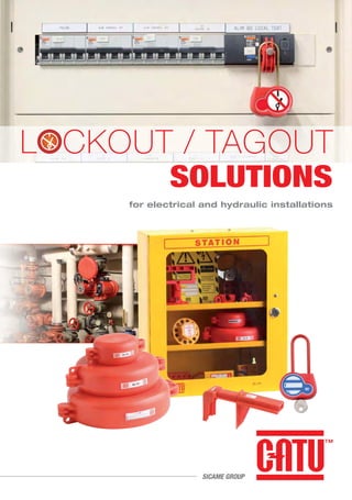
- 1. for electrical and hydraulic installations LOCKOUT / TAGOUT SOLUTIONS SICAME GROUP
- 3. CONTENTS Locking padlocks 5 and accessories Locking equipment for modular switchgear 15 and controlgear Fluid 19 locking Miscellaneous 23 Reference index 26 ELECTRICALFLUID
- 4. 4 LOCKING, an essential stage for lockout. Irrespective of whether servicing or work involves an item of electrical installation or work equipment, a lockout must be done to ensure the safety of the teams working on the job. • Continued presence of live conductor parts for electrical installations. • Presence of pressurized fluids (hydraulic circuits). • Presence of unstable mechanical systems. Depending on the environments, default lockout accidents are caused by the: The corresponding recommendations must be applied for each risk, but in all cases specific locking with regard to the risk considered must be set up. Sometimes the overall analysis of risks reveals a combination of the different risks which makes a more extensive locking operation mandatory. This is especially the case with electricity production equipment. What does locking mean? The purpose of locking is to separate cut off or neutralisation parts with a suitable, and sufficiently protected system to prevent any operation by unauthorised persons (switching on power for an electrical installation). Locking is generally accompanied by signs. For the electrical domain, setting up and removing the lockout are described in French and European standards (EN50110-1). For electricity production equipment. More generally, the safety recommendations are included in Directive CE7: 2009/104/EC on the minimum health and safety recommendations for using work equipment.
- 6. Locking padlocks 6 Lockingpadlocksandaccessories Locking padlocks prevent any separation unit (circuit breaker, cabinet, etc.) from being used. In brass to prevent any corrosion, it is protected by two plastic covers with signs. mm Diameter g Weight mm Total height INDEX Special models with pictograms Reference AL-230-(**)-EX AL-230-S-(**)-EX AL-230-Z-EX AL-230-S-Z-EX AL-240-(**)-EX AL-240-S-(**)-EX AL-240-Z-EX AL-240-S-Z-EX 50 70 50 70 50 70 50 70 6 6 6 6 4 4 4 4 204 214 204 214 192 198 192 198 g mm mm (**) Add the key numbers 111 or 222 only. Shackle AL-230-…-EX AL-240-…-EX mm Reference AL-260-(**)-EX AL-260-00-EX AL-260-Z-EX AL-260-S-(**)-EX AL-260-S-00-EX AL-260-S-Z-EX Shackle Colour 50 50 50 70 70 70 6,2 6,2 6,2 6,2 6,2 6,2 200 200 200 210 210 210 gmm Models with insulated shackle Shackle covered with insulating red PVC. (**) Add the key numbers 111 or 222 only. AL-260-...-EX AL-260-S-...- EX
- 8. Choose your locks! 8 Lockingpadlocksandaccessories A complete line of AL padlocks to meet all of your needs Shackle diameter Shackle length Body colours Ø 4 mm 240 Ø 6 mm 230 50 mm – 70 mm S Red – White B Yellow J Blue BL Green V Ø 6.2 mm 260 Stickers Picto EX Keys Random Z Standard (*) Upon request 00 Bill of material as a reference for your padlocks: AL - XXX - X - X - XXXX - XX To order your padlocks (*) : Standard key number, 111 - 1111 - 222 - 2222 - 333 - 3333 - 444 - 4444 - 555 - 5555 - 666 - 6666 - 777 - 7777 - 888 - 8888 - 999 - 9999. (**) : Key number 111 or 222 only. Z : Number of random key (at random). 00 : Key number on request. Codes or key numbers Shackle Ø: 240 (Ø 4 mm) or 230 (Ø 6 mm) or 260 (Ø 6.2 mm) Shackle length: nothing or S (50 or 70 mm) Colour: nothing or B or J or BL or V or OR Stickers: EX Key: number from 111 to 9999 or Z or 00 1St example : Insulated shackle Ø 6.2 mm..........AL-260 Shackle Lg 50 mm.............................– Standard colour (red) .........................– Key n°222 .......................................222 Sticker with picto..............................EX Your reference: AL-260-222-EX 2nd example : Shackle Ø 4 mm ...........................AL-240 Shackle Lg 70 mm.............................S Colour blue.......................................BL Key upon request..............................00 Sticker with picto..............................EX Your reference: AL-240-S-BL-00-EX Isolated ring
- 9. 9 Lockingpadlocksandaccessories Tables of possible combinations Existing padlocks. Existing padlocks. Key Sticker (*) (**) Z 00 CATU, also provides ... ... a comprehensive multiple lockers range, all-plastic or metal models. See page 10 Ø6mm Ø4mm Key Sticker (*) (**) Z 00 AL-230 (Ø 6 mm) Shackle 50 mm L Shackle 70 mm L - B J BL V - B J BL V AL-260 (Ø 6.2 mm - insulated shackle) Shackle 50 mm L Shackle 70 mm L - B J BL V - B J BL V AL-240 (Ø 4 mm) Shackle 50 mm L Shackle 70 mm L - B J BL V - B J BL V
- 10. Multiple lockers 10 Lockingpadlocksandaccessories mm Diameter mm Dimensions Number of locks Cable g Weight mm Total height mm Total length INDEX Multiple lockers enable several users to lock a single item of equipment. Operation can only be resumed after the last padlock has been removed. Flexible models Nylon (non-conductive) . Reference ALP-03 ALP-06 Shackle Holes 50 80 3 6 105 183 mm 9 9 mm 20 30 g mm g mm All-plastic models Nylon (non-conductive). Label with 'DANGER' warning and identification of the person carrying out the work. Holds 4 padlocks. Reference ALP-4/3 ALP-4/6 Shackle Holes 46 46 3 6 108 108 35 35 4 4 mm mm 8 8 mm Universal model Steel cable coated in non-conductive PVC. Maximum weight supported: 100kg. 'DANGER' warning label. Reference ALP-12/2M Holes Ø4 Lg2m 12 130 g mm 9 ALP-03 ALP-06 ALP-4/6 ALP-4/3
- 11. 11 Lockingpadlocksandaccessories mm Steel shackle model High-strength steel shackle and body. Label with 'DANGER' warning and identification of the person carrying out the work. Holds 6 padlocks. Reference ALM-6/8 Shackle Holes 25 5 115 g 80 mm mm 8 mm mm HASP models Reference ALM-6/25 ALM-6/38 ALM-20/45 Clamping Holes 25 38 20 & 31 6 6 6 112 125 138 g 95 110 120 mm 9 9 9 mm Metal models Reference Description AL-200 AL-202 100 x 60 x 10 165 x 50 x 12 EDF type A EDF type B 150 200 g Reference AL-203 * 6 50 180 g mm mm Safety padlock mm * Key n°111. AL-200 AL-202 ALM-6/25 ALM-6/38 ALM-20/45 Shackle
- 12. Padlock stations 12 Lockingpadlocksandaccessories mm Diameter mm Dimensions Number of locks g Weight INDEXHandle systems for 6 to 30 padlocks. It ensures that general lockouts with multiple padlocks are implemented correctly. Fixed models or models for 12-padlock belt. Yellow PVC handle model Fitted to the belt so as to free up the hands. Key ring incorporated into the handle. Label system ensures that the user knows that all the power sources have been locked out. Reference AL-212 Holes 12 190 x 130 mm 9 mm 120 g Ivory handle model Ivory white PVC. High resistance to impacts. Reference AL-207/30 Holes 30 130 mm 9 g
- 13. 13 Lockingpadlocksandaccessories 'Lockout manager' model Housing with openings for keys. Plastic handle with 6 padlocks that are all opened with the same key. * 00 : key number on demand. Reference AL-236-111-EX AL-236-222-EX AL-236-S-111-EX AL-236-S-222-EX AL-236-00-EX AL-236-S-00-EX 6 (AL-230-111-EX) 6 (AL-230-222-EX) 6 (AL-230-S-111-EX) 6 (AL-230-S-222-EX) 6 (AL-230-00-EX *) 6 (AL-230-S-00-EX *) 1150 1150 1210 1210 1150 1210 g Wall support for padlocks Red-painted metal wall support. Reference RL-100 12 175 x 71 31 mm 65 g mm 4500 g Storage cabinet Red-painted metal cabinet. Plexiglas window Locked by key. Delivered with 4-level padlock support, attachment pegs and screws. Reference SL-102 42 465 x 395 x 55
- 14. CATU, also provides ... ... a comprehensive lockout range. www.catuelec.com Tel:+44 (0)1914901547 Fax:+44(0)1914775371 Email:northernsales@thorneandderrick.co.uk Website:www.cablejoints.co.uk www.thorneanderrick.co.uk
- 16. Circuit breaker lockers 16 Lockingequipmentformodularswitchgearandcontrolgear mm Diameter mm Dimensions Number of locks Packaging INDEX Circuit breaker lockers prevent switches from being operated. They can be installed easily without tools and locked by one or more padlocks. g Weight ClipblockTM small model Quick fitting with a no. 3 flat screwdriver. Highly compact and can be padlocked. Prohibition sign. Delivered in blister pack. Reference Description and AL-201/1 AL-201-C/1 5 units, no padlock Comes with 1 padlock 158 60 g 110 160 g Multiple model Suitable for all types of low voltage protection unit locker. Particularly suited to the CLIPBLOCKTM circuit breaker locker. Reference Description and AL-205 AL-205/5 2 parts - delivered without padlock or locker AL-201/1. 2 parts - delivered with 5m cord. Delivered without padlock or locker AL-201/1.
- 17. 17 Lockingequipmentformodularswitchgearandcontrolgear Medium-size models Red PVC. Easy installation without tools (tightened manually). Trip worm to allow space for the padlock shackle. Reference AL-208-C* AL-208-D** 4 4 Stainless steel Stainless steel Screw 20 20 Holes mm Large model Easy installation without tools. Turn the screw in the circuit breaker handle and add one or more padlocks and a warning label. AL-208-C* AL-208-D** Reference AL-209-L Holes 12 76 x 23 mm 8 mm 66 g g Model for moulded units Epoxy painted steel. Suitable for Schneider circuit breakers with the following references: NS80, NSE75/NSE100, NS100/NS160/NS250, NSF150/NSF250, NS400/NS630, NSJ400/NSJ600. Reference AL-204 Trous 3 37x 49 x 4* mm 8 mm 32 g * Bent snipe nose. ** Straight. * Close.
- 18. Panels and inserts locking – lockout 18 Lockingequipmentformodularswitchgearandcontrolgear mm Diameter mm Dimensions Packaging INDEX The warning signs and badges, made of flexible or rigid PVC ensure that the locking is visible and effective. Can be customised using all types of pens (ballpoint, felt tip pens, etc.) 1 2 3 5 FIRST, SELECT THE RIGHT EQUIPEMENTS EN 50110 LOCKED APPARATUS FORBIDDEN TO OPERATE + + + + Detex 3 T REF : AP-510-BT-GB MO-11000 or MO-11001 CG-10-B MS-911 AL-230-GB AL-318 AL-32/05 MP-42/11 or MP-42/16 LOCKED APPARATUS FORBIDDEN TO OPERATE 4 DEAD WORKING LOW VOLTAGE FIVE GOLDEN RULES 4 1 Isolate the installation from sources of supply. 2 Lock the isolation devices in the open position. Check the absence of voltage. 3 Identify the work. 5 Show warm others. Protect the work area from the close live parts. DRAWING Badge models Ø 10mm hole for attachment on the upper part. Reference AM-467-GB AP-499/1 80 100 Aluminium Plastic Typemm AP-467-GB AP-499/1 CATU, also provides ... ... a full range of warning signs.
- 20. 20 Fluidlocking Valve lockers mm Diameter Number of locks mm Total lenght INDEX Valve lockers prevent any handling and lock "quarter turn" or gate valves. Padlock locking and can be customized using pens (ball point, felt tip, etc.). g Weight Models for gate valves Polyurethane. Easy to install with the two articulated parts*. Padlock locking. Prevents any handling of the gate valve. * Except HL-105, 2 parts. ** 4 position settings. Reference HL-100 HL-101 HL-102 HL-103 HL-104 HL-105 Holes Gate 6 8 9 9 9 9 1 2 3 3 3 1** 70 140 172 260 370 – mm Ext. mm 45 170 250 505 1055 225 g 25 - 63,5 63,5 - 127 127 - 165 165 - 254 254 - 355 25 - 165 mm HL-100 HL-101 HL-102 HL-105 POLYPROPYLENE ADJUSTABLE MODEL
- 21. 21 Fluidlocking Models for 1/4 turn valves Polyurethane. Easy to adjust with the two clip-in parts Padlock locking that prevents any quarter turn handling. Reference Locking HL-200 HL-201 HL-202 Holes 7 7 9 18 positions 113 positions 112 positions 195 254 430 mm 155 230 580 g 9,5 - 31,75 38,1 - 63,5 50,8 - 203,2 mm HL-202 HL-203 HL-201 HL-200 Universal model Polypropylene. For locking all types of valves: 1/4 turn, butterfly, etc. Reference Locking HL-203 Holes 9 19 positions 300 mm 285 g 95 à 255 mm ADJUSTABLE MODEL
- 22. Gas bottle lockers 22 Fluidlocking INDEX The devices can lock gas bottles (butane, propane,etc.), thus preventing any handling of the valve. Padlock locking and fitted with customizable labels. mm Diameter Number of locks mm Total lenght g Weight Gas bottle models Polystyrene. Gas bottle locker device (propane, butane, etc.). Easy to install with the two articulated parts. Padlock locking. Reference Passage GL-100 GL-101 Holes 7 7 1 1 Ø 70 Ø 85-L150 mm 60 135 g 29 35 mm GL-101 GL-100
- 24. Lockers and cabinets 24 Miscellaneous mm Diameter mm Dimensions Number of locks INDEX These lockers are specially designed to prevent any handling of electrical or pneumatic sockets, or machine control units. g Weight Electrical or pneumatic socket lockers Polystyrene. Electrical or pneumatic socket locker device Easy to install with the two articulated parts. Padlock locking. Reference PL-100 PL-101 Holes For cable 7 7 4 4 87 x 50 x 50 171 x 80 x 80 mm 13 23 mm 75 170 g g mm Machine control locker Red fabric and black leather. Locking device for the control units of numerical machines, cranes, winches, overhead cranes. Padlock locking. Reference PL-102 Holes 11 6 460 x 210 mm 65 mm PL-101 PL-100
- 25. 25 Miscellaneous Lockout cabinet Yellow-painted metal. Two adjustable shelves (12 positions). Plexiglas window Locked by key. Delivered empty with attachment pegs and screws Optional accessories. Reference SL-101 405 x 355 x 156 mm 5600 g mm 4500 g Storage cabinet Red-painted metal cabinet. Plexiglas window Locked by key. Delivered with 4-level padlock support, attachment pegs and screws. Reference SL-102 42 465 x 395 x 55
- 26. 26 AL-200............................................................................11 AL-201-C/1 .....................................................................16 AL-201/1.........................................................................16 AL-202............................................................................11 AL-203-(*).......................................................................11 AL-204............................................................................17 AL-205............................................................................16 AL-205/5.........................................................................16 AL-207/30.......................................................................12 AL-208-C ........................................................................17 AL-208-D ........................................................................17 AL-209-L.........................................................................17 AL-212............................................................................12 AL-230-(*).........................................................................6 AL-230-(**)-EX ..................................................................6 AL-230-S-(**)-EX...............................................................6 AL-230-S-Z-EX..................................................................6 AL-230-Z-EX .....................................................................6 AL-236-00-EX .................................................................13 AL-236-111-EX ...............................................................13 AL-236-222-EX ...............................................................13 AL-236-S-00-EX..............................................................13 AL-236-S-111-EX............................................................13 AL-236-S-222-EX............................................................13 AL-240-(**)-EX ..................................................................6 AL-240-B-00-EX................................................................7 AL-240-B-111-EX..............................................................7 AL-240-B-222-EX..............................................................7 AL-240-B-Z-EX..................................................................7 AL-240-BL-00-EX..............................................................7 AL-240-BL-111-EX............................................................7 AL-240-BL-222-EX............................................................7 AL-240-BL-Z-EX................................................................7 AL-240-J-00-EX................................................................7 AL-240-J-111-EX..............................................................7 AL-240-J-222-EX..............................................................7 AL-240-J-Z-EX..................................................................7 AL-240-S-(**)-EX...............................................................6 AL-240-S-B-00-EX............................................................7 AL-240-S-B-111-EX..........................................................7 AL-240-S-B-222-EX..........................................................7 AL-240-S-BL-00-EX..........................................................7 AL-240-S-BL-111-EX........................................................7 AL-240-S-BL-222-EX........................................................7 AL-240-S-J-00-EX ............................................................7 AL-240-S-J-111-EX ..........................................................7 AL-240-S-J-222-EX ..........................................................7 AL-240-S-V-00-EX ............................................................7 AL-240-S-V-111-EX ..........................................................7 AL-240-S-V-222-EX ..........................................................7 AL-240-S-Z-EX..................................................................6 AL-240-V-00-EX................................................................7 AL-240-V-111-EX..............................................................7 AL-240-V-222-EX..............................................................7 AL-240-V-Z-EX..................................................................7 AL-240-Z-EX .....................................................................6 AL-260-(**)-EX ..................................................................6 AL-260-00-EX...................................................................6 AL-260-S-(**)-EX...............................................................6 AL-260-S-00-EX................................................................6 AL-260-S-Z-EX..................................................................6 AL-260-Z-EX .....................................................................6 ALM-20/45......................................................................11 ALM-6/25........................................................................11 ALM-6/38........................................................................11 ALM-6/8..........................................................................11 ALP-03............................................................................10 ALP-06............................................................................10 ALP-12/2M......................................................................10 ALP-4/3...........................................................................10 ALP-4/6...........................................................................10 AM-467-GB.....................................................................18 AP-499/1.........................................................................18 GL-100............................................................................22 GL-101............................................................................22 HL-100............................................................................20 HL-101............................................................................20 HL-102............................................................................20 HL-103............................................................................20 HL-104............................................................................20 HL-105............................................................................20 HL-200............................................................................21 HL-201............................................................................21 HL-202............................................................................21 HL-203............................................................................21 PL-100............................................................................24 PL-101............................................................................24 PL-102............................................................................24 RL-100............................................................................13 SL-101............................................................................25 SL-102.......................................................................13/25 Reference Page Reference Page Reference index
- 27. The characteristics and technical informations stated in our literature are only for your guidance and therefore cannot be considered as contractual. Our company is entitled to modify at any time the characteristics of its equipment. In case of modification of these characteristics, our company would not be obliged to supply materials conform to those previously in force. Non contractual photographs Design / direction / layout: COMST © 2013 CATU S.A. BAGNEUX All reproduction, adaptation and translation rights reserved for all countries.
- 28. SICAME GROUP 10/20 Avenue Jean-Jaurès - B.P.2 - 92222 BAGNEUX Cedex Téléphone : (33) 01 42 31 46 46 - Fax : (33) 01 42 31 46 32 www.catuelec.com Distributed by: ComST06/2013 Tel:+44 (0)1914901547 Fax:+44(0)1914775371 Email:northernsales@thorneandderrick.co.uk Website:www.cablejoints.co.uk www.thorneanderrick.co.uk