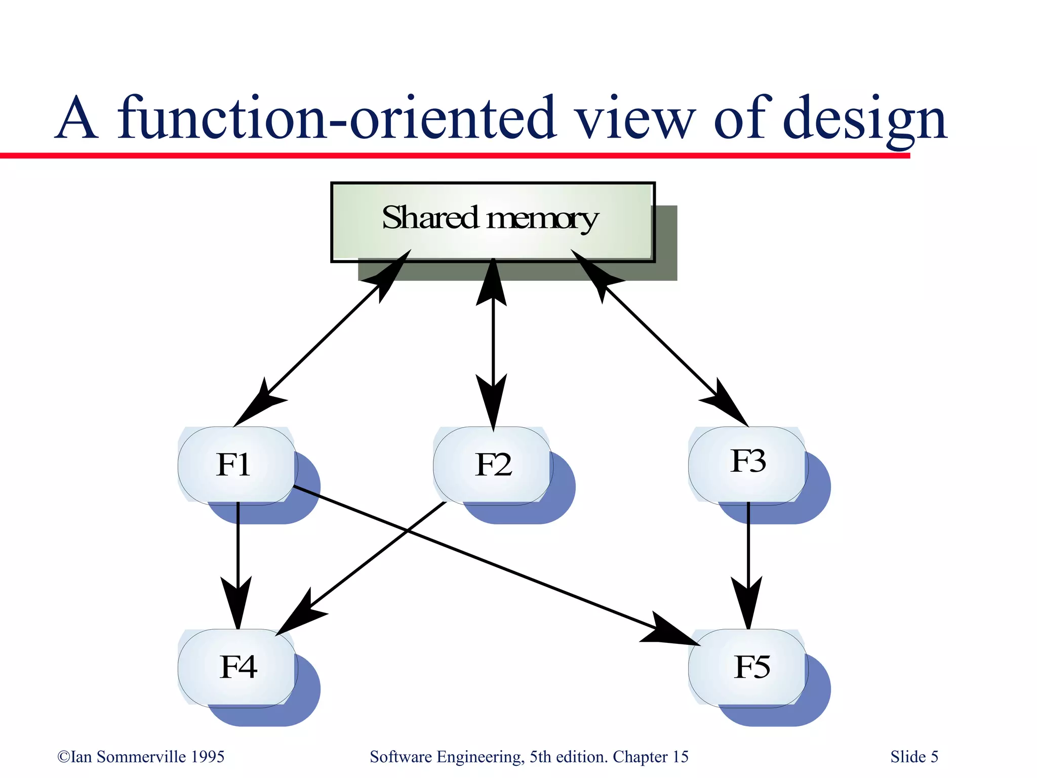
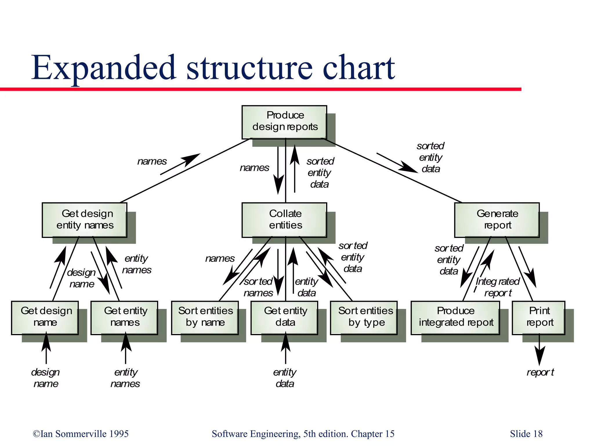
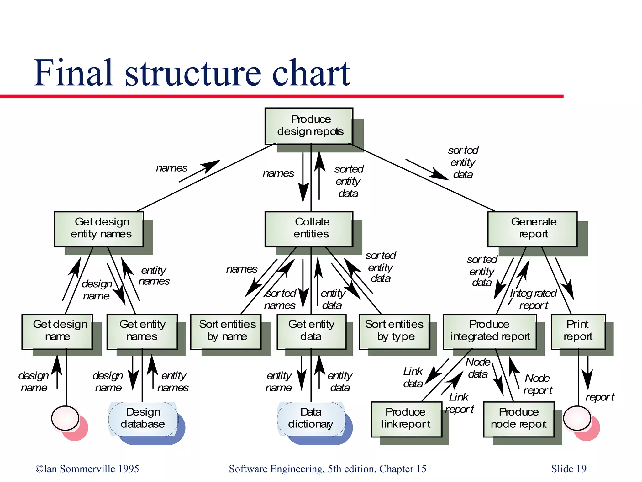
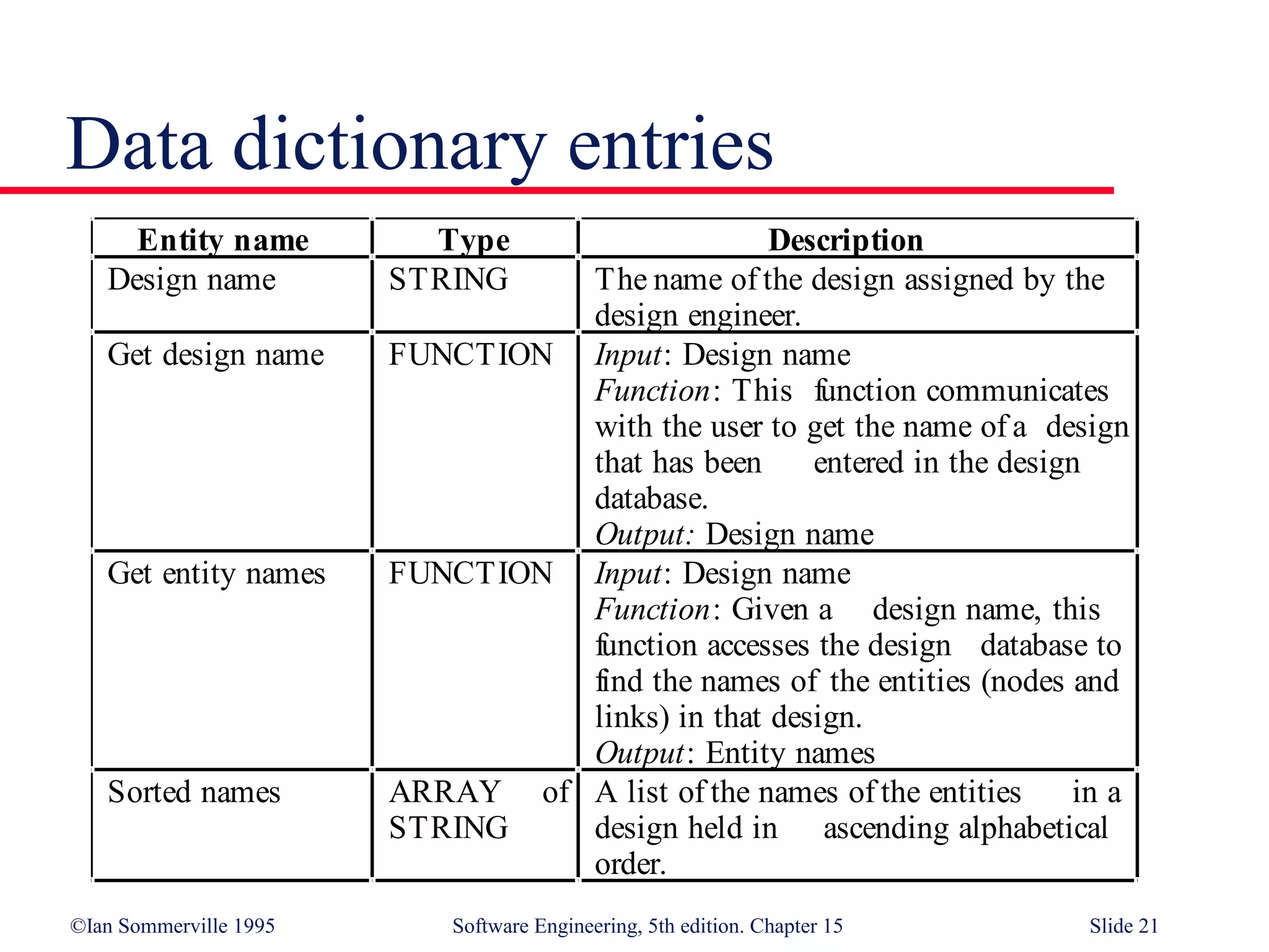
©Ian Sommerville 1995 Software Engineering, 5th edition. Chapter 15 Slide 1
Function-oriented design
Design with functional units
which transform inputs to
outputs
©Ian Sommerville 1995 Software Engineering, 5th edition. Chapter 15 Slide 2
Objectives
To explain how a software design may be
represented as aset of functions which share state
To introduce notations for funciton-oriented
design
To illustrate the function-oriented design process
by example
To compare sequential, concurrent abd object-
oriented design strategies
©Ian Sommerville 1995 Software Engineering, 5th edition. Chapter 15 Slide 3
Topics covered
data-flow design
Structural decomposition
Detailed design
A comparison of design strategies
©Ian Sommerville 1995 Software Engineering, 5th edition. Chapter 15 Slide 4
Function-oriented design
Practised informally since programming began
Thousands of systems have been developed
using this approach
Supported directly by most programming
languages
Most design methods are functional in their
approach
CASE tools are available for design support
©Ian Sommerville 1995 Software Engineering, 5th edition. Chapter 15 Slide 5
A function-oriented view of design
F2F1 F3
F4 F5
Shared memory
©Ian Sommerville 1995 Software Engineering, 5th edition. Chapter 15 Slide 6
Natural functional systems
Some systems are naturally function-oriented
Systems which maintain minimal state
information i.e. where the system is concerned
with processing independent actions whose
outcomes are not affected by previous actions
Information sharing through parameter lists
Transaction processing systems fall into this
category. Each transaction is independent
©Ian Sommerville 1995 Software Engineering, 5th edition. Chapter 15 Slide 7
An ATM system design
Replace with portrait slide
©Ian Sommerville 1995 Software Engineering, 5th edition. Chapter 15 Slide 8
Functional and object-oriented design
For many types of application, object-oriented
deisgn is likely to lead to a more reliable and
maintainable system
Some applications maintain little state - function-
oriented design is appropriate
Standards, methods and CASE tools for
functional design are well-established
Existing systems must be maintained -
function-oriented design will be practised well
into the 21st century
©Ian Sommerville 1995 Software Engineering, 5th edition. Chapter 15 Slide 9
Functional design process
Data-flow design
• Model the data processing in the system using data-flow
diagrams
Structural decomposition
• Model how functions are decomposed to sub-functions using
graphical structure charts
Detailed design
• The entities in the design and their interfaces are described in
detail. These may be recorded in a data dictionary and the
design expressed using a PDL
©Ian Sommerville 1995 Software Engineering, 5th edition. Chapter 15 Slide 10
Data flow diagrams
Show how an input data item is functionally
transformed by a system into an output data
item
Are an integral part of many design methods
and are supported by many CASE systems
May be translated into either a sequential or
parallel design. In a sequential design,
processing elements are functions or
procedures; in a parallel design, processing
elements are tasks or processes
©Ian Sommerville 1995 Software Engineering, 5th edition. Chapter 15 Slide 11
DFD notation
Rounded rectangle - function or transform
Rectangle - data store
Circles - user interactions with the system
Arrows - show direction of data flow
keywords and/ or. Used to link data flows
©Ian Sommerville 1995 Software Engineering, 5th edition. Chapter 15 Slide 12
Design report generator
Replace with portrait slide
©Ian Sommerville 1995 Software Engineering, 5th edition. Chapter 15 Slide 13
Structural decomposition is concerned with
developing a model of the design which shows
the dynamic structure i.e. function calls
This is not the same as the static composition
structure
The aim of the designer should be to derive
design units which are highly cohesive and
loosely coupled
In essence, a data flow diagram is converted to a
structure chart
Structural decomposition
©Ian Sommerville 1995 Software Engineering, 5th edition. Chapter 15 Slide 14
Decomposition guidelines
For business applications, the top-level structure
chart may have four functions namely input,
process, master-file-update and output
Data validation functions should be subordinate
to an input function
Coordination and control should be the
responsibility of functions near the top of the
hierarchy
©Ian Sommerville 1995 Software Engineering, 5th edition. Chapter 15 Slide 15
Decomposition guidelines
The aim of the deisgn process is to identify
loosely couypled, highly cohesive functions.
Each function should therefore do one thing and
one thing only
Each node in the structure chart should have
between two and seven subordinates
©Ian Sommerville 1995 Software Engineering, 5th edition. Chapter 15 Slide 16
Process steps
Identify system processing transformations
• Transformations in the DFD which are concerned with
processing rather than input/output activities. Group under a
single function in the structure chart
Identify input transformations
• Transformations concerned with reading, validating and
formatting inputs. Group under the input function
Identify output transformations
• Transformations concerned with formatting and writing output.
Group under the output function
©Ian Sommerville 1995 Software Engineering, 5th edition. Chapter 15 Slide 17
Initial structure chart
Produce
designreports
Collate
entities
Generate
report
Get design
entity names
Design
name
Design
entity
names
Design
report
entity
names
entity
data
entity
data
entity
names
©Ian Sommerville 1995 Software Engineering, 5th edition. Chapter 15 Slide 18
Expanded structure chart
Produce
designreports
Collate
entities
Generate
report
Get design
entity names
entity
names
names
sorted
entity
datanames
Get design
name
Get entity
names
Sort entities
by name
Get entity
data
Sort entities
by type
Produce
integrated report
Print
report
design
name
entity
names
repor tentity
data
design
name
names
sorted
names
entity
data
sorted
entity
data
sorted
entity
data
Integrated
repor t
sorted
entity
data
©Ian Sommerville 1995 Software Engineering, 5th edition. Chapter 15 Slide 19
Final structure chart
Data
dictionary
Produce
designreports
Collate
entities
Generate
report
Get design
entity names
entity
names
names
sorted
entity
datanames
Get design
name
Get entity
names
Sort entities
by name
Get entity
data
Sort entities
by type
Produce
integrated report
Print
report
design
name
entity
names
report
entity
data
design
name
names
sorted
names
entity
data
sorted
entity
data
sorted
entity
data
Integrated
report
Design
database
design
name
entity
name
Produce
linkreport
Produce
node report
Link
data
Link
report
Node
data Node
report
sorted
entity
data
©Ian Sommerville 1995 Software Engineering, 5th edition. Chapter 15 Slide 20
Detailed design
Concerned with producing a short design
specification (minispec) of each function. This
should describe the processing, inputs and
outputs
These descriptions should be managed in a data
dictionary
From these descriptions, detailed design
descriptions, expressed in a PDL or programming
language, can be produced
©Ian Sommerville 1995 Software Engineering, 5th edition. Chapter 15 Slide 21
Data dictionary entries
Entity name Type Description
Design name STRING The name of the design assigned by the
design engineer.
Get design name FUNCTION Input: Design name
Function: This function communicates
with the user to get the name of a design
that has been entered in the design
database.
Output: Design name
Get entity names FUNCTION Input: Design name
Function: Given a design name, this
function accesses the design database to
find the names of the entities (nodes and
links) in that design.
Output: Entity names
Sorted names ARRAY of
STRING
A list of the names of the entities in a
design held in ascending alphabetical
order.
©Ian Sommerville 1995 Software Engineering, 5th edition. Chapter 15 Slide 22
Function-oriented design relies on identifying
functions which transform inputs to outputs
Many business systems are transaction processing
systems which are naturally functional
The functional design process involves
identifying data transformations, decomposing
functions into sub-functions and describing these
in detail
35
Key points
©Ian Sommerville 1995 Software Engineering, 5th edition. Chapter 15 Slide 23
Key points
Data-flow diagrams are a means of documenting
end-to-end data flow. Structure charts represent
the dynamic hierarchy of function calls
Data flow diagrams can be implemented directly
as cooperating sequential processes
Functional and object-oriented design result in
different system decompositions. However, a
heterogeous approach to design is often necessary

Function Oriented Design

  • 1.
    ©Ian Sommerville 1995Software Engineering, 5th edition. Chapter 15 Slide 1 Function-oriented design Design with functional units which transform inputs to outputs
  • 2.
    ©Ian Sommerville 1995Software Engineering, 5th edition. Chapter 15 Slide 2 Objectives To explain how a software design may be represented as aset of functions which share state To introduce notations for funciton-oriented design To illustrate the function-oriented design process by example To compare sequential, concurrent abd object- oriented design strategies
  • 3.
    ©Ian Sommerville 1995Software Engineering, 5th edition. Chapter 15 Slide 3 Topics covered data-flow design Structural decomposition Detailed design A comparison of design strategies
  • 4.
    ©Ian Sommerville 1995Software Engineering, 5th edition. Chapter 15 Slide 4 Function-oriented design Practised informally since programming began Thousands of systems have been developed using this approach Supported directly by most programming languages Most design methods are functional in their approach CASE tools are available for design support
  • 5.
    ©Ian Sommerville 1995Software Engineering, 5th edition. Chapter 15 Slide 5 A function-oriented view of design F2F1 F3 F4 F5 Shared memory
  • 6.
    ©Ian Sommerville 1995Software Engineering, 5th edition. Chapter 15 Slide 6 Natural functional systems Some systems are naturally function-oriented Systems which maintain minimal state information i.e. where the system is concerned with processing independent actions whose outcomes are not affected by previous actions Information sharing through parameter lists Transaction processing systems fall into this category. Each transaction is independent
  • 7.
    ©Ian Sommerville 1995Software Engineering, 5th edition. Chapter 15 Slide 7 An ATM system design Replace with portrait slide
  • 8.
    ©Ian Sommerville 1995Software Engineering, 5th edition. Chapter 15 Slide 8 Functional and object-oriented design For many types of application, object-oriented deisgn is likely to lead to a more reliable and maintainable system Some applications maintain little state - function- oriented design is appropriate Standards, methods and CASE tools for functional design are well-established Existing systems must be maintained - function-oriented design will be practised well into the 21st century
  • 9.
    ©Ian Sommerville 1995Software Engineering, 5th edition. Chapter 15 Slide 9 Functional design process Data-flow design • Model the data processing in the system using data-flow diagrams Structural decomposition • Model how functions are decomposed to sub-functions using graphical structure charts Detailed design • The entities in the design and their interfaces are described in detail. These may be recorded in a data dictionary and the design expressed using a PDL
  • 10.
    ©Ian Sommerville 1995Software Engineering, 5th edition. Chapter 15 Slide 10 Data flow diagrams Show how an input data item is functionally transformed by a system into an output data item Are an integral part of many design methods and are supported by many CASE systems May be translated into either a sequential or parallel design. In a sequential design, processing elements are functions or procedures; in a parallel design, processing elements are tasks or processes
  • 11.
    ©Ian Sommerville 1995Software Engineering, 5th edition. Chapter 15 Slide 11 DFD notation Rounded rectangle - function or transform Rectangle - data store Circles - user interactions with the system Arrows - show direction of data flow keywords and/ or. Used to link data flows
  • 12.
    ©Ian Sommerville 1995Software Engineering, 5th edition. Chapter 15 Slide 12 Design report generator Replace with portrait slide
  • 13.
    ©Ian Sommerville 1995Software Engineering, 5th edition. Chapter 15 Slide 13 Structural decomposition is concerned with developing a model of the design which shows the dynamic structure i.e. function calls This is not the same as the static composition structure The aim of the designer should be to derive design units which are highly cohesive and loosely coupled In essence, a data flow diagram is converted to a structure chart Structural decomposition
  • 14.
    ©Ian Sommerville 1995Software Engineering, 5th edition. Chapter 15 Slide 14 Decomposition guidelines For business applications, the top-level structure chart may have four functions namely input, process, master-file-update and output Data validation functions should be subordinate to an input function Coordination and control should be the responsibility of functions near the top of the hierarchy
  • 15.
    ©Ian Sommerville 1995Software Engineering, 5th edition. Chapter 15 Slide 15 Decomposition guidelines The aim of the deisgn process is to identify loosely couypled, highly cohesive functions. Each function should therefore do one thing and one thing only Each node in the structure chart should have between two and seven subordinates
  • 16.
    ©Ian Sommerville 1995Software Engineering, 5th edition. Chapter 15 Slide 16 Process steps Identify system processing transformations • Transformations in the DFD which are concerned with processing rather than input/output activities. Group under a single function in the structure chart Identify input transformations • Transformations concerned with reading, validating and formatting inputs. Group under the input function Identify output transformations • Transformations concerned with formatting and writing output. Group under the output function
  • 17.
    ©Ian Sommerville 1995Software Engineering, 5th edition. Chapter 15 Slide 17 Initial structure chart Produce designreports Collate entities Generate report Get design entity names Design name Design entity names Design report entity names entity data entity data entity names
  • 18.
    ©Ian Sommerville 1995Software Engineering, 5th edition. Chapter 15 Slide 18 Expanded structure chart Produce designreports Collate entities Generate report Get design entity names entity names names sorted entity datanames Get design name Get entity names Sort entities by name Get entity data Sort entities by type Produce integrated report Print report design name entity names repor tentity data design name names sorted names entity data sorted entity data sorted entity data Integrated repor t sorted entity data
  • 19.
    ©Ian Sommerville 1995Software Engineering, 5th edition. Chapter 15 Slide 19 Final structure chart Data dictionary Produce designreports Collate entities Generate report Get design entity names entity names names sorted entity datanames Get design name Get entity names Sort entities by name Get entity data Sort entities by type Produce integrated report Print report design name entity names report entity data design name names sorted names entity data sorted entity data sorted entity data Integrated report Design database design name entity name Produce linkreport Produce node report Link data Link report Node data Node report sorted entity data
  • 20.
    ©Ian Sommerville 1995Software Engineering, 5th edition. Chapter 15 Slide 20 Detailed design Concerned with producing a short design specification (minispec) of each function. This should describe the processing, inputs and outputs These descriptions should be managed in a data dictionary From these descriptions, detailed design descriptions, expressed in a PDL or programming language, can be produced
  • 21.
    ©Ian Sommerville 1995Software Engineering, 5th edition. Chapter 15 Slide 21 Data dictionary entries Entity name Type Description Design name STRING The name of the design assigned by the design engineer. Get design name FUNCTION Input: Design name Function: This function communicates with the user to get the name of a design that has been entered in the design database. Output: Design name Get entity names FUNCTION Input: Design name Function: Given a design name, this function accesses the design database to find the names of the entities (nodes and links) in that design. Output: Entity names Sorted names ARRAY of STRING A list of the names of the entities in a design held in ascending alphabetical order.
  • 22.
    ©Ian Sommerville 1995Software Engineering, 5th edition. Chapter 15 Slide 22 Function-oriented design relies on identifying functions which transform inputs to outputs Many business systems are transaction processing systems which are naturally functional The functional design process involves identifying data transformations, decomposing functions into sub-functions and describing these in detail 35 Key points
  • 23.
    ©Ian Sommerville 1995Software Engineering, 5th edition. Chapter 15 Slide 23 Key points Data-flow diagrams are a means of documenting end-to-end data flow. Structure charts represent the dynamic hierarchy of function calls Data flow diagrams can be implemented directly as cooperating sequential processes Functional and object-oriented design result in different system decompositions. However, a heterogeous approach to design is often necessary