SlideShare a Scribd company logo
1 of 8
Download to read offline
6017180 Rev. B
INSTALLATION MANUAL
FOR SIT-STAND WORKSTATION
Weight Capacity: 6.5-24.5 lbs.
Contents
Tools Required / Supplied Part Kits / Warnings/Disclaimers..........2
Base Installation
	 Clamp Mount Base Location...............................................3
	 Grommet Mount Base Orientation.......................................4
Pivot Limiter Installation............................................................5
Attaching the Arm to the Base...................................................5
Installing Work Surface.............................................................6
Installing Monitor......................................................................6
Cable Management Installation..................................................7
Arm Counterbalance Adjustments..............................................7
Tray Leveling Adjustments (Left to Right)....................................8
Monitor Adjustments.................................................................8
Monitor Tilt Tension Adjustment.................................................8
INSTALLATION WARNINGS:
•	 Read the entire instruction manual before beginning any installation or assembly.
•	 The installer must verify that the attachment surface can safely support the
	 combined weight of all the attached equipment and hardware.
•	 Improper installation of this product may cause extensive property damage
	 or serious personal injury, either during or after installation.
DISCLAIMERS:
•	 The manufacturer will bear no responsibility for any damages of any kind
	 arising from improper installation of this product.
•	 In no way will the manufacturer be held liable for any damage to the monitor,
	 property or personal injury should an outside force either intentionally or
	 unintentional be applied to the monitor or monitor mounting bracket
ADJUSTMENT NOTIFICATIONS:
•	 Routine maintenance checks and adjustments are suggested to properly
	 support the quality and optimal performance of this product.
	 Refer to adjustment suggestions on last page of booklet, or contact your
	 distributor for further detailed information.
•	 Over tightening of bolts during installation or adjustments can damage
	 the product and affect the function and warranty.
Allen Keys,
1/8",3/16",
7/32",1/4"
3/8" Wrench
(for Dual Monitor option)
Tools Required
Supplied Part Kits
#2 Phillips
Screwdriver
Level
Warnings/Disclaimers
KIT A: Arm Bolt/Washer Kit
KIT C:
Work Surface Installation Kit
KIT D: VESA
Mounting Plate Kit
KIT B: Grommet Mounting Bolt Kit
2 Installation Manual: SIT-STAND WORKSTATION
The unit can be installed on a 24" or 30" deep rectangular or corner desk using the integral desk clamp or grommet
mounting hardware provided.
Base Installation
Clamp Mount Base Location
Determine desired installed tray location. Offset base location by 22" left or right for a 24" deep desk or
21" left or right for a 30" deep desk.
Slide the angle bracket assembly onto the back of the desk.
Secure the clamp plate to the underside of the desk with the
supplied bolts. Use a 7/32" Allen Key to tighten to 75 in-lbs.
To reverse the bottom clamp, remove the three screws using a 3/16" Allen
Key and reinstall the Bottom Clamp in the DOWNWARD position. Slide the
angle bracket assembly onto the back of the desk. Secure the clamp plate
to the underside of the desk with the supplied bolts. Use a 7/32" Allen Key
to tighten to 75 in-lbs.
Bottom Clamp is UPWARD. Bottom Clamp is DOWNWARD.
DESK THICKNESS - 3/4" - 1 1
/2" DESK THICKNESS - 1 1
/2" - 2 1
/2"
3Installation Manual: SIT-STAND WORKSTATION
22”
22" 21”
21"
24" DEEP DESK 30" DEEP DESK
STEP 1
STEP 2
The thickness of the desk will determine the orientation of the bottom clamp. The product comes pre-configured for a 3/4" - 1 1
/2" desk.
Bottom
Clamp
Bottom
Clamp
Angle
Bracket
Angle
Bracket
Clamp Plate
Clamp Plate
Grommet Mount Base Orientation
If installer is drilling their own hole, ensure that the diameter is a minimum of 1/2".
STEP 1
STEP 2
STEP 3
4 Installation Manual: SIT-STAND WORKSTATION
Tighten the bolt securely under
the desk using a 7/32" Allen Key
to 75 in-lbs.
Detach the angle bracket assembly (not used in a
grommet application) by removing the 4 screws
with a 7/32" Allen Key.
Insert the grommet bolt through the washer (KIT B: Grommet Mounting
Bolt) and upward facing clamp plate. From under the desk insert the
grommet bolt assembly through the desk into the center hole of the base.
With the base already installed on the desk.
Attaching the Arm to the Base
STEP 1
Slide the large nylon washer
(KIT A: Arm Bolt/Washer Kit)
over the bottom pin of the arm.
STEP 2
Set the main arm bottom pin
into the base.
STEP 3
While holding the arm in the lowest
position remove the trim cap at the
back of the arm.
STEP 4
Hold the arm in the lowest position to
prevent it from springing up, insert the
bolt/washer assembly (KIT A: Arm
Bolt/Washer Kit) through the back of
the arm and into the base. Ensure the
washers are installed as illustrated.
STEP 5
Keeping the arm down tighten the bolt with a
1/4" Allen Key until the bolt is seated and snug.
Tighten or loosen bolt to obtain desired resistance
for left to right arm movement.
STEP 6
Replace the trim cap at the back of the arm.
STEP 5
STEP 6
NOTE: Ensure nylon bushing is on the arm post when inserting the arm into the base.
5Installation Manual: SIT-STAND WORKSTATION
Make sure the pin remains engaged in the arm base
when the arm is attached to the desk mount base.
Pivot Limiter Installation
Do not overtighten bolt as
this may cause damage
to the product.
!
STEP 2
STEP 1
STEP 4
STEP 3
PIVOT LIMITER VIEW FROM UNDERSIDE
Lightly tap the pin to
ensure it stays in place
during installation.
The pin should only
protrude 1/4" once
fully seated.
ALLOWS 180° ROTATION
Position pin at 12:00
to prevent the arm from
coming in direct contact
with the wall on either side
180°
Plastic
Steel
For this step, the installer needs to determine if they wish to use the Quick Connect adapter
supplied or mount the monitor directly to the VESA mount on the monitor tower.
Installing Monitor (6.5 lbs. to 24.5 lbs.)
SINGLE-MONITOR
If using the Quick Connect adapter, mount the Quick
Connect adapter (Kit D: VESA Mounting Plate Kit) to back
of the monitor with the screws provided.
Use a #2 Phillips screwdriver to secure screws. Lift monitor
into position and slide the Quick Connect onto the VESA.
If not using the Quick Connect adapter, mount the monitor
directly to the VESA mount on the monitor tower with the
screws provided. Use a #2 Phillips screwdriver to secure.
DUAL-MONITOR (Optional Dual Monitor Kit)
Attach the dual bracket to the monitor tower VESA with the hardware
provided in the Dual Monitor Kit.
To attach monitors see steps for single-monitor.
NOTE: Adjustable bracket supports most 24" monitors
weighing up to 10 lbs. each.
6 Installation Manual: SIT-STAND WORKSTATION
Installing Work Surface
BELOW THE MOUNTING PLATE
STEP 1
Secure foam pads onto each corner on the underside
of the tray and remove warning sticker.
STEP 2
Position the work surface underneath the mounting
plate aligning all four holes and securing the tray with
the four screws (KIT C: Work Surface Installation Kit).
Use a 1/8" Allen Key and hand-tighten until slightly
recessed.
STEP 3
Snap cap into place.
ABOVE THE MOUNTING PLATE
STEP 1
Secure foam pads onto each corner on the underside of the tray
and remove warning sticker.
STEP 2
Position the work surface above the mounting plate
aligning all four holes and securing the tray with the four
screws (KIT C: Work Surface Installation Kit). Use a
1/8" Allen Key and hand-tighten until flush.
STEP 3
Snap cap into place.
The work surface can be mounted above or below the mounting plate.
Do not overtighten
screws as this may cause
damage to the product.
!
SLIGHTLY
RECESSED
DO NOT
OVERTIGHTEN
STEP 2
After the technology has been installed, ensure
there is enough slack in the cables from the
monitor, keyboard and mouse along with any
other peripherals.
Arm adjustment is to be made after all technology has been installed from 6.5 lbs. to 24.5 lbs.
Cable Management Installation
Arm Counterbalance Adjustments
ATTENTION:
Arm must be held down to perform this adjustment.
STEP 1
Remove the trim cap at the back
of the arm.
STEP 2
Keeping the arm down, use
a 1/4" Allen Key to turn the
middle bolt at the back of
the arm. Turning the bolt
CLOCKWISE decreases the
spring force reducing the counter
balance load. Turning the bolt
COUNTERCLOCKWISE increases
the spring force increasing the
counter balance load.
STEP 3
Adjust the middle bolt until the
arm counter balance is acceptable.
STEP 4
Replace the trim cap at the back
of the arm.
+ –+ –
– +–
COUNTERBALANCE
ADJUST
Do not overtighten bolt as
this may cause damage
to the product.
!
1/4"
Allen Key
STEP 2 & 3
7Installation Manual: SIT-STAND WORKSTATION
STEP 1
Locate the two cable management
clips under the arm. Gently open
each of the clips.
STEP 2
Place all required technology cables
(power cord, mouse cable, VGA etc.)
through the clips under the monitor arm.
Make sure to leave enough slack in the
cables to allow the arm to move freely.
STEP 3
Gently close the clips to secure the
cables in place. Re-adjust slack in the
cables if necessary.
Tray adjustment is to be made after all technology has been installed.
Tray Leveling adjustments (Left to Right)
STEP 1
Remove the trim cap at the back of the arm.
STEP 2
Keeping the arm down, use the 3/16" Allen Key
to turn the top bolt at the back of the arm.
Turn the bolt until the tray is level.
STEP 3
Confirm that surface is level with spirit level.
STEP 4
Replace the trim cap at the back of the arm.
+ –+ –
+ – +–
LEVEL
ADJUST
3/16"
Allen
Key
ATTENTION:
Tray must be placed in its in-use position and be
parallel to the work surface when adjusting.
STEP 3
STEP 2
Monitor Tilt Tension Adjustment
Monitor Height Adjustments
STEP 1
To adjust the monitor tilt tension, use a 3/16"
Allen Key to adjust the tension setting on both
sides of the VESA plate. Setting number 1 is for
light monitors and 4 is for heavier monitors.
The factory default setting is 1.
STEP 2
Adjust the setting screw until a desirable tension
is achieved.
Hold and support the monitor before loosening the
monitor tower knob. Turn the monitor tower knob
counterclockwise to loosen. Move the monitor
to desired location. Turn the monitor tower knob
clockwise to tighten.
6017180 Rev. B
STEP 4
Do not over rotate the dial beyond
“1” or “4” position or possible
damage to the dial may occur.!
+
–
+
–
+
–
+
–
+
–
+
–
+
–
+
–
+
–
+
–
+
–
+
–
1. Adjust tension as necessary
2. Repeat on alternate side
Light
monitor
Heavy
monitor
1 2
3
4
1 2
3
4

More Related Content

What's hot

ZipView Unison Dual Monitor Arm with Handle User Manual
ZipView Unison Dual Monitor Arm with Handle User ManualZipView Unison Dual Monitor Arm with Handle User Manual
ZipView Unison Dual Monitor Arm with Handle User ManualiMovR
 
SteadyType Exo Ergodynamic Keyboard Tray User Instructions
SteadyType Exo Ergodynamic Keyboard Tray User InstructionsSteadyType Exo Ergodynamic Keyboard Tray User Instructions
SteadyType Exo Ergodynamic Keyboard Tray User InstructionsiMovR
 
Trackless keyboardtray manual
Trackless keyboardtray manualTrackless keyboardtray manual
Trackless keyboardtray manualiMovR
 
Tempo Dual Screen Two-Arm Manual
Tempo Dual Screen Two-Arm ManualTempo Dual Screen Two-Arm Manual
Tempo Dual Screen Two-Arm ManualiMovR
 
iMovR TopView Dual Monitor Arm
iMovR TopView Dual Monitor ArmiMovR TopView Dual Monitor Arm
iMovR TopView Dual Monitor ArmiMovR
 
iMovR TopView Max Monitor Arm
iMovR TopView Max Monitor ArmiMovR TopView Max Monitor Arm
iMovR TopView Max Monitor ArmiMovR
 
iMovR TopView Single Monitor Arm Instructions
iMovR TopView Single Monitor Arm InstructionsiMovR TopView Single Monitor Arm Instructions
iMovR TopView Single Monitor Arm InstructionsiMovR
 
iMovR ZipView Unison Dual Monitor Arm with Handle - Instruction Manual
iMovR ZipView Unison Dual Monitor Arm with Handle - Instruction ManualiMovR ZipView Unison Dual Monitor Arm with Handle - Instruction Manual
iMovR ZipView Unison Dual Monitor Arm with Handle - Instruction ManualiMovR
 
iMovR Lander L-Desk User Manual
iMovR Lander L-Desk User ManualiMovR Lander L-Desk User Manual
iMovR Lander L-Desk User ManualiMovR
 
Cadence plus installation manual
Cadence plus installation manualCadence plus installation manual
Cadence plus installation manualiMovR
 
iMovR Xtend Monitor Arm Manual
iMovR Xtend Monitor Arm ManualiMovR Xtend Monitor Arm Manual
iMovR Xtend Monitor Arm ManualiMovR
 
ZipView Dual Monitor Arm - Assembly
ZipView Dual Monitor Arm - AssemblyZipView Dual Monitor Arm - Assembly
ZipView Dual Monitor Arm - AssemblyiMovR
 
ZipView Single Monitor Arm - Assembly
ZipView Single Monitor Arm - AssemblyZipView Single Monitor Arm - Assembly
ZipView Single Monitor Arm - AssemblyiMovR
 
Lander L-Desk Installation Manual
Lander L-Desk Installation Manual Lander L-Desk Installation Manual
Lander L-Desk Installation Manual iMovR
 
iMovR TopView Dual Monitor Arm
iMovR TopView Dual Monitor ArmiMovR TopView Dual Monitor Arm
iMovR TopView Dual Monitor ArmiMovR
 
Tempo tread top-office_chair_manual
Tempo tread top-office_chair_manualTempo tread top-office_chair_manual
Tempo tread top-office_chair_manualiMovR
 
TopView Heavy Duty
TopView Heavy DutyTopView Heavy Duty
TopView Heavy DutyiMovR
 

What's hot (20)

ZipView Unison Dual Monitor Arm with Handle User Manual
ZipView Unison Dual Monitor Arm with Handle User ManualZipView Unison Dual Monitor Arm with Handle User Manual
ZipView Unison Dual Monitor Arm with Handle User Manual
 
SteadyType Exo Ergodynamic Keyboard Tray User Instructions
SteadyType Exo Ergodynamic Keyboard Tray User InstructionsSteadyType Exo Ergodynamic Keyboard Tray User Instructions
SteadyType Exo Ergodynamic Keyboard Tray User Instructions
 
Trackless keyboardtray manual
Trackless keyboardtray manualTrackless keyboardtray manual
Trackless keyboardtray manual
 
Tempo Dual Screen Two-Arm Manual
Tempo Dual Screen Two-Arm ManualTempo Dual Screen Two-Arm Manual
Tempo Dual Screen Two-Arm Manual
 
iMovR TopView Dual Monitor Arm
iMovR TopView Dual Monitor ArmiMovR TopView Dual Monitor Arm
iMovR TopView Dual Monitor Arm
 
iMovR TopView Max Monitor Arm
iMovR TopView Max Monitor ArmiMovR TopView Max Monitor Arm
iMovR TopView Max Monitor Arm
 
iMovR TopView Single Monitor Arm Instructions
iMovR TopView Single Monitor Arm InstructionsiMovR TopView Single Monitor Arm Instructions
iMovR TopView Single Monitor Arm Instructions
 
iMovR ZipView Unison Dual Monitor Arm with Handle - Instruction Manual
iMovR ZipView Unison Dual Monitor Arm with Handle - Instruction ManualiMovR ZipView Unison Dual Monitor Arm with Handle - Instruction Manual
iMovR ZipView Unison Dual Monitor Arm with Handle - Instruction Manual
 
iMovR Lander L-Desk User Manual
iMovR Lander L-Desk User ManualiMovR Lander L-Desk User Manual
iMovR Lander L-Desk User Manual
 
Cadence plus installation manual
Cadence plus installation manualCadence plus installation manual
Cadence plus installation manual
 
iMovR Xtend Monitor Arm Manual
iMovR Xtend Monitor Arm ManualiMovR Xtend Monitor Arm Manual
iMovR Xtend Monitor Arm Manual
 
ZipView Dual Monitor Arm - Assembly
ZipView Dual Monitor Arm - AssemblyZipView Dual Monitor Arm - Assembly
ZipView Dual Monitor Arm - Assembly
 
ZipView Single Monitor Arm - Assembly
ZipView Single Monitor Arm - AssemblyZipView Single Monitor Arm - Assembly
ZipView Single Monitor Arm - Assembly
 
Lander L-Desk Installation Manual
Lander L-Desk Installation Manual Lander L-Desk Installation Manual
Lander L-Desk Installation Manual
 
iMovR TopView Dual Monitor Arm
iMovR TopView Dual Monitor ArmiMovR TopView Dual Monitor Arm
iMovR TopView Dual Monitor Arm
 
Tempo tread top-office_chair_manual
Tempo tread top-office_chair_manualTempo tread top-office_chair_manual
Tempo tread top-office_chair_manual
 
TopView Heavy Duty
TopView Heavy DutyTopView Heavy Duty
TopView Heavy Duty
 
NexusBot Assembly and Control Manual v0.1 (English)
NexusBot Assembly and Control Manual v0.1 (English)NexusBot Assembly and Control Manual v0.1 (English)
NexusBot Assembly and Control Manual v0.1 (English)
 
Nexus:bit User Manual v0.1 (English)
Nexus:bit User Manual v0.1 (English)Nexus:bit User Manual v0.1 (English)
Nexus:bit User Manual v0.1 (English)
 
Nexus bot assembly manual
Nexus bot assembly manualNexus bot assembly manual
Nexus bot assembly manual
 

Similar to iMovR Cadence Express Standing Desk Converter Installation Manual

iMovR TopView Max Unison Monitor Arm
iMovR TopView Max Unison Monitor ArmiMovR TopView Max Unison Monitor Arm
iMovR TopView Max Unison Monitor ArmiMovR
 
iMovr Omega Olympus Manual 12 24-15
iMovr Omega Olympus Manual 12 24-15iMovr Omega Olympus Manual 12 24-15
iMovr Omega Olympus Manual 12 24-15iMovR
 
iMovR Vigor: 2 Leg Kit Installation Manual
iMovR Vigor: 2 Leg Kit Installation ManualiMovR Vigor: 2 Leg Kit Installation Manual
iMovR Vigor: 2 Leg Kit Installation ManualiMovR
 
Lander L- & U-Desk Assembly Instructions and User Manual
Lander L- & U-Desk Assembly Instructions and User ManualLander L- & U-Desk Assembly Instructions and User Manual
Lander L- & U-Desk Assembly Instructions and User ManualiMovR
 
How to assemble a sink base vanity 48 60
How to assemble a sink base vanity 48 60How to assemble a sink base vanity 48 60
How to assemble a sink base vanity 48 60Domain CabinetsDirect
 
iMovR Vigor: 3 Leg Kit Installation Manual
iMovR Vigor: 3 Leg Kit Installation ManualiMovR Vigor: 3 Leg Kit Installation Manual
iMovR Vigor: 3 Leg Kit Installation ManualiMovR
 
Installation Manual: Height Adjustable Table - Three Leg Kit
Installation Manual: Height Adjustable Table - Three Leg KitInstallation Manual: Height Adjustable Table - Three Leg Kit
Installation Manual: Height Adjustable Table - Three Leg KitiMovR
 
Lander L-Desk Installation Manual
Lander L-Desk Installation Manual Lander L-Desk Installation Manual
Lander L-Desk Installation Manual iMovR
 
20 x 30 Presto Canopy Tent
20 x 30 Presto Canopy Tent20 x 30 Presto Canopy Tent
20 x 30 Presto Canopy Tentcelinatent
 
UpTown Adjustable-Height Desk System Installation Manual
UpTown Adjustable-Height Desk System Installation ManualUpTown Adjustable-Height Desk System Installation Manual
UpTown Adjustable-Height Desk System Installation ManualiMovR
 
Concerto Monitor Arm Manual
Concerto Monitor Arm ManualConcerto Monitor Arm Manual
Concerto Monitor Arm ManualiMovR
 
Installation Manual: Height Adjustable Table - Two Leg Kit
Installation Manual: Height Adjustable Table - Two Leg KitInstallation Manual: Height Adjustable Table - Two Leg Kit
Installation Manual: Height Adjustable Table - Two Leg KitiMovR
 
Lander DIY Assembly Guide
Lander DIY Assembly GuideLander DIY Assembly Guide
Lander DIY Assembly GuideiMovR
 
Lander Desk DIY Assembly Manual
Lander Desk DIY Assembly ManualLander Desk DIY Assembly Manual
Lander Desk DIY Assembly ManualiMovR
 
Ms200 Install Asphalt
Ms200 Install AsphaltMs200 Install Asphalt
Ms200 Install Asphaltdteich
 
Sliding Door Installation Procedure
Sliding Door Installation ProcedureSliding Door Installation Procedure
Sliding Door Installation ProcedureJustin Bucher
 
Articulator 1 /certified fixed orthodontic courses by Indian dental academy
Articulator 1 /certified fixed orthodontic courses by Indian dental academy Articulator 1 /certified fixed orthodontic courses by Indian dental academy
Articulator 1 /certified fixed orthodontic courses by Indian dental academy Indian dental academy
 

Similar to iMovR Cadence Express Standing Desk Converter Installation Manual (20)

iMovR TopView Max Unison Monitor Arm
iMovR TopView Max Unison Monitor ArmiMovR TopView Max Unison Monitor Arm
iMovR TopView Max Unison Monitor Arm
 
iMovr Omega Olympus Manual 12 24-15
iMovr Omega Olympus Manual 12 24-15iMovr Omega Olympus Manual 12 24-15
iMovr Omega Olympus Manual 12 24-15
 
iMovR Vigor: 2 Leg Kit Installation Manual
iMovR Vigor: 2 Leg Kit Installation ManualiMovR Vigor: 2 Leg Kit Installation Manual
iMovR Vigor: 2 Leg Kit Installation Manual
 
Lander L- & U-Desk Assembly Instructions and User Manual
Lander L- & U-Desk Assembly Instructions and User ManualLander L- & U-Desk Assembly Instructions and User Manual
Lander L- & U-Desk Assembly Instructions and User Manual
 
How to assemble a sink base vanity
How to assemble a sink base vanityHow to assemble a sink base vanity
How to assemble a sink base vanity
 
How to assemble a sink base vanity 48 60
How to assemble a sink base vanity 48 60How to assemble a sink base vanity 48 60
How to assemble a sink base vanity 48 60
 
iMovR Vigor: 3 Leg Kit Installation Manual
iMovR Vigor: 3 Leg Kit Installation ManualiMovR Vigor: 3 Leg Kit Installation Manual
iMovR Vigor: 3 Leg Kit Installation Manual
 
Monza-SGT.Altus-Spine.pdf
Monza-SGT.Altus-Spine.pdfMonza-SGT.Altus-Spine.pdf
Monza-SGT.Altus-Spine.pdf
 
Installation Manual: Height Adjustable Table - Three Leg Kit
Installation Manual: Height Adjustable Table - Three Leg KitInstallation Manual: Height Adjustable Table - Three Leg Kit
Installation Manual: Height Adjustable Table - Three Leg Kit
 
Lander L-Desk Installation Manual
Lander L-Desk Installation Manual Lander L-Desk Installation Manual
Lander L-Desk Installation Manual
 
20 x 30 Presto Canopy Tent
20 x 30 Presto Canopy Tent20 x 30 Presto Canopy Tent
20 x 30 Presto Canopy Tent
 
UpTown Adjustable-Height Desk System Installation Manual
UpTown Adjustable-Height Desk System Installation ManualUpTown Adjustable-Height Desk System Installation Manual
UpTown Adjustable-Height Desk System Installation Manual
 
Rolling Art Rack Panels Installation Instructions
Rolling Art Rack Panels Installation InstructionsRolling Art Rack Panels Installation Instructions
Rolling Art Rack Panels Installation Instructions
 
Concerto Monitor Arm Manual
Concerto Monitor Arm ManualConcerto Monitor Arm Manual
Concerto Monitor Arm Manual
 
Installation Manual: Height Adjustable Table - Two Leg Kit
Installation Manual: Height Adjustable Table - Two Leg KitInstallation Manual: Height Adjustable Table - Two Leg Kit
Installation Manual: Height Adjustable Table - Two Leg Kit
 
Lander DIY Assembly Guide
Lander DIY Assembly GuideLander DIY Assembly Guide
Lander DIY Assembly Guide
 
Lander Desk DIY Assembly Manual
Lander Desk DIY Assembly ManualLander Desk DIY Assembly Manual
Lander Desk DIY Assembly Manual
 
Ms200 Install Asphalt
Ms200 Install AsphaltMs200 Install Asphalt
Ms200 Install Asphalt
 
Sliding Door Installation Procedure
Sliding Door Installation ProcedureSliding Door Installation Procedure
Sliding Door Installation Procedure
 
Articulator 1 /certified fixed orthodontic courses by Indian dental academy
Articulator 1 /certified fixed orthodontic courses by Indian dental academy Articulator 1 /certified fixed orthodontic courses by Indian dental academy
Articulator 1 /certified fixed orthodontic courses by Indian dental academy
 

More from iMovR

Lander Standing Desk User Manual
Lander Standing Desk User ManualLander Standing Desk User Manual
Lander Standing Desk User ManualiMovR
 
iMovR Premium Drawer Drill Template
iMovR Premium Drawer Drill TemplateiMovR Premium Drawer Drill Template
iMovR Premium Drawer Drill TemplateiMovR
 
Tech Dock Instruction Manual
Tech Dock Instruction ManualTech Dock Instruction Manual
Tech Dock Instruction ManualiMovR
 
Standing mat-study-texas-am-university-2013
Standing mat-study-texas-am-university-2013Standing mat-study-texas-am-university-2013
Standing mat-study-texas-am-university-2013iMovR
 
INSTALLATION INSTRUCTIONS RONDO MICRO PASS-THROUGH GROMMET WITH COVER (NO POWER)
INSTALLATION INSTRUCTIONS RONDO MICRO PASS-THROUGH GROMMET WITH COVER (NO POWER)INSTALLATION INSTRUCTIONS RONDO MICRO PASS-THROUGH GROMMET WITH COVER (NO POWER)
INSTALLATION INSTRUCTIONS RONDO MICRO PASS-THROUGH GROMMET WITH COVER (NO POWER)iMovR
 
Spacer kit instructions
Spacer kit instructions Spacer kit instructions
Spacer kit instructions iMovR
 
Installation Instructions for Rondo Micro USB-C 18W and 60W
Installation Instructions for Rondo Micro USB-C 18W and 60WInstallation Instructions for Rondo Micro USB-C 18W and 60W
Installation Instructions for Rondo Micro USB-C 18W and 60WiMovR
 
Captains Desk Instruction Manual
 Captains Desk Instruction Manual  Captains Desk Instruction Manual
Captains Desk Instruction Manual iMovR
 
Rondo Micro USB-C 18W Instruction Manual
Rondo Micro USB-C 18W Instruction ManualRondo Micro USB-C 18W Instruction Manual
Rondo Micro USB-C 18W Instruction ManualiMovR
 
Rondo Micro AC Outlet Instruction Manual
Rondo Micro AC Outlet Instruction ManualRondo Micro AC Outlet Instruction Manual
Rondo Micro AC Outlet Instruction ManualiMovR
 
Captain's Desk Standing Desk Instruction Manual
Captain's Desk Standing Desk Instruction ManualCaptain's Desk Standing Desk Instruction Manual
Captain's Desk Standing Desk Instruction ManualiMovR
 
Stowaway Ergonomic Keyboard Tray Installation Manual
Stowaway Ergonomic Keyboard Tray Installation ManualStowaway Ergonomic Keyboard Tray Installation Manual
Stowaway Ergonomic Keyboard Tray Installation ManualiMovR
 
Neemo Ergonomic Chair User Guide
Neemo Ergonomic Chair User GuideNeemo Ergonomic Chair User Guide
Neemo Ergonomic Chair User GuideiMovR
 
iMovR's McHale Advanced Ergonomic Chair User Guide
iMovR's McHale Advanced Ergonomic Chair User GuideiMovR's McHale Advanced Ergonomic Chair User Guide
iMovR's McHale Advanced Ergonomic Chair User GuideiMovR
 
iMovR TopView Max Unison Monitor Arm
iMovR TopView Max Unison Monitor ArmiMovR TopView Max Unison Monitor Arm
iMovR TopView Max Unison Monitor ArmiMovR
 
iMovR TopView Max Monitor Arm
iMovR TopView Max Monitor ArmiMovR TopView Max Monitor Arm
iMovR TopView Max Monitor ArmiMovR
 
iMovR TopView Single Monitor Arm
iMovR TopView Single Monitor ArmiMovR TopView Single Monitor Arm
iMovR TopView Single Monitor ArmiMovR
 

More from iMovR (17)

Lander Standing Desk User Manual
Lander Standing Desk User ManualLander Standing Desk User Manual
Lander Standing Desk User Manual
 
iMovR Premium Drawer Drill Template
iMovR Premium Drawer Drill TemplateiMovR Premium Drawer Drill Template
iMovR Premium Drawer Drill Template
 
Tech Dock Instruction Manual
Tech Dock Instruction ManualTech Dock Instruction Manual
Tech Dock Instruction Manual
 
Standing mat-study-texas-am-university-2013
Standing mat-study-texas-am-university-2013Standing mat-study-texas-am-university-2013
Standing mat-study-texas-am-university-2013
 
INSTALLATION INSTRUCTIONS RONDO MICRO PASS-THROUGH GROMMET WITH COVER (NO POWER)
INSTALLATION INSTRUCTIONS RONDO MICRO PASS-THROUGH GROMMET WITH COVER (NO POWER)INSTALLATION INSTRUCTIONS RONDO MICRO PASS-THROUGH GROMMET WITH COVER (NO POWER)
INSTALLATION INSTRUCTIONS RONDO MICRO PASS-THROUGH GROMMET WITH COVER (NO POWER)
 
Spacer kit instructions
Spacer kit instructions Spacer kit instructions
Spacer kit instructions
 
Installation Instructions for Rondo Micro USB-C 18W and 60W
Installation Instructions for Rondo Micro USB-C 18W and 60WInstallation Instructions for Rondo Micro USB-C 18W and 60W
Installation Instructions for Rondo Micro USB-C 18W and 60W
 
Captains Desk Instruction Manual
 Captains Desk Instruction Manual  Captains Desk Instruction Manual
Captains Desk Instruction Manual
 
Rondo Micro USB-C 18W Instruction Manual
Rondo Micro USB-C 18W Instruction ManualRondo Micro USB-C 18W Instruction Manual
Rondo Micro USB-C 18W Instruction Manual
 
Rondo Micro AC Outlet Instruction Manual
Rondo Micro AC Outlet Instruction ManualRondo Micro AC Outlet Instruction Manual
Rondo Micro AC Outlet Instruction Manual
 
Captain's Desk Standing Desk Instruction Manual
Captain's Desk Standing Desk Instruction ManualCaptain's Desk Standing Desk Instruction Manual
Captain's Desk Standing Desk Instruction Manual
 
Stowaway Ergonomic Keyboard Tray Installation Manual
Stowaway Ergonomic Keyboard Tray Installation ManualStowaway Ergonomic Keyboard Tray Installation Manual
Stowaway Ergonomic Keyboard Tray Installation Manual
 
Neemo Ergonomic Chair User Guide
Neemo Ergonomic Chair User GuideNeemo Ergonomic Chair User Guide
Neemo Ergonomic Chair User Guide
 
iMovR's McHale Advanced Ergonomic Chair User Guide
iMovR's McHale Advanced Ergonomic Chair User GuideiMovR's McHale Advanced Ergonomic Chair User Guide
iMovR's McHale Advanced Ergonomic Chair User Guide
 
iMovR TopView Max Unison Monitor Arm
iMovR TopView Max Unison Monitor ArmiMovR TopView Max Unison Monitor Arm
iMovR TopView Max Unison Monitor Arm
 
iMovR TopView Max Monitor Arm
iMovR TopView Max Monitor ArmiMovR TopView Max Monitor Arm
iMovR TopView Max Monitor Arm
 
iMovR TopView Single Monitor Arm
iMovR TopView Single Monitor ArmiMovR TopView Single Monitor Arm
iMovR TopView Single Monitor Arm
 

Recently uploaded

WhatsApp 9892124323 ✓Call Girls In Khar ( Mumbai ) secure service - Bandra F...
WhatsApp 9892124323 ✓Call Girls In Khar ( Mumbai ) secure service -  Bandra F...WhatsApp 9892124323 ✓Call Girls In Khar ( Mumbai ) secure service -  Bandra F...
WhatsApp 9892124323 ✓Call Girls In Khar ( Mumbai ) secure service - Bandra F...Pooja Nehwal
 
(办理学位证)加州州立大学北岭分校毕业证成绩单原版一比一
(办理学位证)加州州立大学北岭分校毕业证成绩单原版一比一(办理学位证)加州州立大学北岭分校毕业证成绩单原版一比一
(办理学位证)加州州立大学北岭分校毕业证成绩单原版一比一Fi sss
 
(MEGHA) Hinjewadi Call Girls Just Call 7001035870 [ Cash on Delivery ] Pune E...
(MEGHA) Hinjewadi Call Girls Just Call 7001035870 [ Cash on Delivery ] Pune E...(MEGHA) Hinjewadi Call Girls Just Call 7001035870 [ Cash on Delivery ] Pune E...
(MEGHA) Hinjewadi Call Girls Just Call 7001035870 [ Cash on Delivery ] Pune E...ranjana rawat
 
定制(Salford学位证)索尔福德大学毕业证成绩单原版一比一
定制(Salford学位证)索尔福德大学毕业证成绩单原版一比一定制(Salford学位证)索尔福德大学毕业证成绩单原版一比一
定制(Salford学位证)索尔福德大学毕业证成绩单原版一比一ss ss
 
Vip Noida Escorts 9873940964 Greater Noida Escorts Service
Vip Noida Escorts 9873940964 Greater Noida Escorts ServiceVip Noida Escorts 9873940964 Greater Noida Escorts Service
Vip Noida Escorts 9873940964 Greater Noida Escorts Serviceankitnayak356677
 
办理(CSU毕业证书)澳洲查理斯特大学毕业证成绩单原版一比一
办理(CSU毕业证书)澳洲查理斯特大学毕业证成绩单原版一比一办理(CSU毕业证书)澳洲查理斯特大学毕业证成绩单原版一比一
办理(CSU毕业证书)澳洲查理斯特大学毕业证成绩单原版一比一diploma 1
 
(办理学位证)多伦多大学毕业证成绩单原版一比一
(办理学位证)多伦多大学毕业证成绩单原版一比一(办理学位证)多伦多大学毕业证成绩单原版一比一
(办理学位证)多伦多大学毕业证成绩单原版一比一C SSS
 
定制(UI学位证)爱达荷大学毕业证成绩单原版一比一
定制(UI学位证)爱达荷大学毕业证成绩单原版一比一定制(UI学位证)爱达荷大学毕业证成绩单原版一比一
定制(UI学位证)爱达荷大学毕业证成绩单原版一比一ss ss
 
vip Model Basti Call Girls 9999965857 Call or WhatsApp Now Book
vip Model Basti Call Girls 9999965857 Call or WhatsApp Now Bookvip Model Basti Call Girls 9999965857 Call or WhatsApp Now Book
vip Model Basti Call Girls 9999965857 Call or WhatsApp Now Bookmanojkuma9823
 
原版1:1复刻斯坦福大学毕业证Stanford毕业证留信学历认证
原版1:1复刻斯坦福大学毕业证Stanford毕业证留信学历认证原版1:1复刻斯坦福大学毕业证Stanford毕业证留信学历认证
原版1:1复刻斯坦福大学毕业证Stanford毕业证留信学历认证gwhohjj
 
Gaya Call Girls #9907093804 Contact Number Escorts Service Gaya
Gaya Call Girls #9907093804 Contact Number Escorts Service GayaGaya Call Girls #9907093804 Contact Number Escorts Service Gaya
Gaya Call Girls #9907093804 Contact Number Escorts Service Gayasrsj9000
 
《伯明翰城市大学毕业证成绩单购买》学历证书学位证书区别《复刻原版1:1伯明翰城市大学毕业证书|修改BCU成绩单PDF版》Q微信741003700《BCU学...
《伯明翰城市大学毕业证成绩单购买》学历证书学位证书区别《复刻原版1:1伯明翰城市大学毕业证书|修改BCU成绩单PDF版》Q微信741003700《BCU学...《伯明翰城市大学毕业证成绩单购买》学历证书学位证书区别《复刻原版1:1伯明翰城市大学毕业证书|修改BCU成绩单PDF版》Q微信741003700《BCU学...
《伯明翰城市大学毕业证成绩单购买》学历证书学位证书区别《复刻原版1:1伯明翰城市大学毕业证书|修改BCU成绩单PDF版》Q微信741003700《BCU学...ur8mqw8e
 
萨斯喀彻温大学毕业证学位证成绩单-购买流程
萨斯喀彻温大学毕业证学位证成绩单-购买流程萨斯喀彻温大学毕业证学位证成绩单-购买流程
萨斯喀彻温大学毕业证学位证成绩单-购买流程1k98h0e1
 
Call Girls In Munirka>༒9599632723 Incall_OutCall Available
Call Girls In Munirka>༒9599632723 Incall_OutCall AvailableCall Girls In Munirka>༒9599632723 Incall_OutCall Available
Call Girls In Munirka>༒9599632723 Incall_OutCall AvailableCall Girls in Delhi
 
Call Girls in Dwarka Sub City 💯Call Us 🔝8264348440🔝
Call Girls in Dwarka Sub City 💯Call Us 🔝8264348440🔝Call Girls in Dwarka Sub City 💯Call Us 🔝8264348440🔝
Call Girls in Dwarka Sub City 💯Call Us 🔝8264348440🔝soniya singh
 
vip Krishna Nagar Call Girls 9999965857 Call or WhatsApp Now Book
vip Krishna Nagar Call Girls 9999965857 Call or WhatsApp Now Bookvip Krishna Nagar Call Girls 9999965857 Call or WhatsApp Now Book
vip Krishna Nagar Call Girls 9999965857 Call or WhatsApp Now Bookmanojkuma9823
 
Real Sure (Call Girl) in I.G.I. Airport 8377087607 Hot Call Girls In Delhi NCR
Real Sure (Call Girl) in I.G.I. Airport 8377087607 Hot Call Girls In Delhi NCRReal Sure (Call Girl) in I.G.I. Airport 8377087607 Hot Call Girls In Delhi NCR
Real Sure (Call Girl) in I.G.I. Airport 8377087607 Hot Call Girls In Delhi NCRdollysharma2066
 

Recently uploaded (20)

WhatsApp 9892124323 ✓Call Girls In Khar ( Mumbai ) secure service - Bandra F...
WhatsApp 9892124323 ✓Call Girls In Khar ( Mumbai ) secure service -  Bandra F...WhatsApp 9892124323 ✓Call Girls In Khar ( Mumbai ) secure service -  Bandra F...
WhatsApp 9892124323 ✓Call Girls In Khar ( Mumbai ) secure service - Bandra F...
 
(办理学位证)加州州立大学北岭分校毕业证成绩单原版一比一
(办理学位证)加州州立大学北岭分校毕业证成绩单原版一比一(办理学位证)加州州立大学北岭分校毕业证成绩单原版一比一
(办理学位证)加州州立大学北岭分校毕业证成绩单原版一比一
 
young call girls in Gtb Nagar,🔝 9953056974 🔝 escort Service
young call girls in Gtb Nagar,🔝 9953056974 🔝 escort Serviceyoung call girls in Gtb Nagar,🔝 9953056974 🔝 escort Service
young call girls in Gtb Nagar,🔝 9953056974 🔝 escort Service
 
(MEGHA) Hinjewadi Call Girls Just Call 7001035870 [ Cash on Delivery ] Pune E...
(MEGHA) Hinjewadi Call Girls Just Call 7001035870 [ Cash on Delivery ] Pune E...(MEGHA) Hinjewadi Call Girls Just Call 7001035870 [ Cash on Delivery ] Pune E...
(MEGHA) Hinjewadi Call Girls Just Call 7001035870 [ Cash on Delivery ] Pune E...
 
定制(Salford学位证)索尔福德大学毕业证成绩单原版一比一
定制(Salford学位证)索尔福德大学毕业证成绩单原版一比一定制(Salford学位证)索尔福德大学毕业证成绩单原版一比一
定制(Salford学位证)索尔福德大学毕业证成绩单原版一比一
 
Vip Noida Escorts 9873940964 Greater Noida Escorts Service
Vip Noida Escorts 9873940964 Greater Noida Escorts ServiceVip Noida Escorts 9873940964 Greater Noida Escorts Service
Vip Noida Escorts 9873940964 Greater Noida Escorts Service
 
9953330565 Low Rate Call Girls In Jahangirpuri Delhi NCR
9953330565 Low Rate Call Girls In Jahangirpuri  Delhi NCR9953330565 Low Rate Call Girls In Jahangirpuri  Delhi NCR
9953330565 Low Rate Call Girls In Jahangirpuri Delhi NCR
 
办理(CSU毕业证书)澳洲查理斯特大学毕业证成绩单原版一比一
办理(CSU毕业证书)澳洲查理斯特大学毕业证成绩单原版一比一办理(CSU毕业证书)澳洲查理斯特大学毕业证成绩单原版一比一
办理(CSU毕业证书)澳洲查理斯特大学毕业证成绩单原版一比一
 
(办理学位证)多伦多大学毕业证成绩单原版一比一
(办理学位证)多伦多大学毕业证成绩单原版一比一(办理学位证)多伦多大学毕业证成绩单原版一比一
(办理学位证)多伦多大学毕业证成绩单原版一比一
 
定制(UI学位证)爱达荷大学毕业证成绩单原版一比一
定制(UI学位证)爱达荷大学毕业证成绩单原版一比一定制(UI学位证)爱达荷大学毕业证成绩单原版一比一
定制(UI学位证)爱达荷大学毕业证成绩单原版一比一
 
vip Model Basti Call Girls 9999965857 Call or WhatsApp Now Book
vip Model Basti Call Girls 9999965857 Call or WhatsApp Now Bookvip Model Basti Call Girls 9999965857 Call or WhatsApp Now Book
vip Model Basti Call Girls 9999965857 Call or WhatsApp Now Book
 
原版1:1复刻斯坦福大学毕业证Stanford毕业证留信学历认证
原版1:1复刻斯坦福大学毕业证Stanford毕业证留信学历认证原版1:1复刻斯坦福大学毕业证Stanford毕业证留信学历认证
原版1:1复刻斯坦福大学毕业证Stanford毕业证留信学历认证
 
Gaya Call Girls #9907093804 Contact Number Escorts Service Gaya
Gaya Call Girls #9907093804 Contact Number Escorts Service GayaGaya Call Girls #9907093804 Contact Number Escorts Service Gaya
Gaya Call Girls #9907093804 Contact Number Escorts Service Gaya
 
《伯明翰城市大学毕业证成绩单购买》学历证书学位证书区别《复刻原版1:1伯明翰城市大学毕业证书|修改BCU成绩单PDF版》Q微信741003700《BCU学...
《伯明翰城市大学毕业证成绩单购买》学历证书学位证书区别《复刻原版1:1伯明翰城市大学毕业证书|修改BCU成绩单PDF版》Q微信741003700《BCU学...《伯明翰城市大学毕业证成绩单购买》学历证书学位证书区别《复刻原版1:1伯明翰城市大学毕业证书|修改BCU成绩单PDF版》Q微信741003700《BCU学...
《伯明翰城市大学毕业证成绩单购买》学历证书学位证书区别《复刻原版1:1伯明翰城市大学毕业证书|修改BCU成绩单PDF版》Q微信741003700《BCU学...
 
young call girls in Khanpur,🔝 9953056974 🔝 escort Service
young call girls in  Khanpur,🔝 9953056974 🔝 escort Serviceyoung call girls in  Khanpur,🔝 9953056974 🔝 escort Service
young call girls in Khanpur,🔝 9953056974 🔝 escort Service
 
萨斯喀彻温大学毕业证学位证成绩单-购买流程
萨斯喀彻温大学毕业证学位证成绩单-购买流程萨斯喀彻温大学毕业证学位证成绩单-购买流程
萨斯喀彻温大学毕业证学位证成绩单-购买流程
 
Call Girls In Munirka>༒9599632723 Incall_OutCall Available
Call Girls In Munirka>༒9599632723 Incall_OutCall AvailableCall Girls In Munirka>༒9599632723 Incall_OutCall Available
Call Girls In Munirka>༒9599632723 Incall_OutCall Available
 
Call Girls in Dwarka Sub City 💯Call Us 🔝8264348440🔝
Call Girls in Dwarka Sub City 💯Call Us 🔝8264348440🔝Call Girls in Dwarka Sub City 💯Call Us 🔝8264348440🔝
Call Girls in Dwarka Sub City 💯Call Us 🔝8264348440🔝
 
vip Krishna Nagar Call Girls 9999965857 Call or WhatsApp Now Book
vip Krishna Nagar Call Girls 9999965857 Call or WhatsApp Now Bookvip Krishna Nagar Call Girls 9999965857 Call or WhatsApp Now Book
vip Krishna Nagar Call Girls 9999965857 Call or WhatsApp Now Book
 
Real Sure (Call Girl) in I.G.I. Airport 8377087607 Hot Call Girls In Delhi NCR
Real Sure (Call Girl) in I.G.I. Airport 8377087607 Hot Call Girls In Delhi NCRReal Sure (Call Girl) in I.G.I. Airport 8377087607 Hot Call Girls In Delhi NCR
Real Sure (Call Girl) in I.G.I. Airport 8377087607 Hot Call Girls In Delhi NCR
 

iMovR Cadence Express Standing Desk Converter Installation Manual

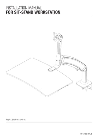
  • 1. 6017180 Rev. B INSTALLATION MANUAL FOR SIT-STAND WORKSTATION Weight Capacity: 6.5-24.5 lbs.
  • 2. Contents Tools Required / Supplied Part Kits / Warnings/Disclaimers..........2 Base Installation Clamp Mount Base Location...............................................3 Grommet Mount Base Orientation.......................................4 Pivot Limiter Installation............................................................5 Attaching the Arm to the Base...................................................5 Installing Work Surface.............................................................6 Installing Monitor......................................................................6 Cable Management Installation..................................................7 Arm Counterbalance Adjustments..............................................7 Tray Leveling Adjustments (Left to Right)....................................8 Monitor Adjustments.................................................................8 Monitor Tilt Tension Adjustment.................................................8 INSTALLATION WARNINGS: • Read the entire instruction manual before beginning any installation or assembly. • The installer must verify that the attachment surface can safely support the combined weight of all the attached equipment and hardware. • Improper installation of this product may cause extensive property damage or serious personal injury, either during or after installation. DISCLAIMERS: • The manufacturer will bear no responsibility for any damages of any kind arising from improper installation of this product. • In no way will the manufacturer be held liable for any damage to the monitor, property or personal injury should an outside force either intentionally or unintentional be applied to the monitor or monitor mounting bracket ADJUSTMENT NOTIFICATIONS: • Routine maintenance checks and adjustments are suggested to properly support the quality and optimal performance of this product. Refer to adjustment suggestions on last page of booklet, or contact your distributor for further detailed information. • Over tightening of bolts during installation or adjustments can damage the product and affect the function and warranty. Allen Keys, 1/8",3/16", 7/32",1/4" 3/8" Wrench (for Dual Monitor option) Tools Required Supplied Part Kits #2 Phillips Screwdriver Level Warnings/Disclaimers KIT A: Arm Bolt/Washer Kit KIT C: Work Surface Installation Kit KIT D: VESA Mounting Plate Kit KIT B: Grommet Mounting Bolt Kit 2 Installation Manual: SIT-STAND WORKSTATION
  • 3. The unit can be installed on a 24" or 30" deep rectangular or corner desk using the integral desk clamp or grommet mounting hardware provided. Base Installation Clamp Mount Base Location Determine desired installed tray location. Offset base location by 22" left or right for a 24" deep desk or 21" left or right for a 30" deep desk. Slide the angle bracket assembly onto the back of the desk. Secure the clamp plate to the underside of the desk with the supplied bolts. Use a 7/32" Allen Key to tighten to 75 in-lbs. To reverse the bottom clamp, remove the three screws using a 3/16" Allen Key and reinstall the Bottom Clamp in the DOWNWARD position. Slide the angle bracket assembly onto the back of the desk. Secure the clamp plate to the underside of the desk with the supplied bolts. Use a 7/32" Allen Key to tighten to 75 in-lbs. Bottom Clamp is UPWARD. Bottom Clamp is DOWNWARD. DESK THICKNESS - 3/4" - 1 1 /2" DESK THICKNESS - 1 1 /2" - 2 1 /2" 3Installation Manual: SIT-STAND WORKSTATION 22” 22" 21” 21" 24" DEEP DESK 30" DEEP DESK STEP 1 STEP 2 The thickness of the desk will determine the orientation of the bottom clamp. The product comes pre-configured for a 3/4" - 1 1 /2" desk. Bottom Clamp Bottom Clamp Angle Bracket Angle Bracket Clamp Plate Clamp Plate
  • 4. Grommet Mount Base Orientation If installer is drilling their own hole, ensure that the diameter is a minimum of 1/2". STEP 1 STEP 2 STEP 3 4 Installation Manual: SIT-STAND WORKSTATION Tighten the bolt securely under the desk using a 7/32" Allen Key to 75 in-lbs. Detach the angle bracket assembly (not used in a grommet application) by removing the 4 screws with a 7/32" Allen Key. Insert the grommet bolt through the washer (KIT B: Grommet Mounting Bolt) and upward facing clamp plate. From under the desk insert the grommet bolt assembly through the desk into the center hole of the base.
  • 5. With the base already installed on the desk. Attaching the Arm to the Base STEP 1 Slide the large nylon washer (KIT A: Arm Bolt/Washer Kit) over the bottom pin of the arm. STEP 2 Set the main arm bottom pin into the base. STEP 3 While holding the arm in the lowest position remove the trim cap at the back of the arm. STEP 4 Hold the arm in the lowest position to prevent it from springing up, insert the bolt/washer assembly (KIT A: Arm Bolt/Washer Kit) through the back of the arm and into the base. Ensure the washers are installed as illustrated. STEP 5 Keeping the arm down tighten the bolt with a 1/4" Allen Key until the bolt is seated and snug. Tighten or loosen bolt to obtain desired resistance for left to right arm movement. STEP 6 Replace the trim cap at the back of the arm. STEP 5 STEP 6 NOTE: Ensure nylon bushing is on the arm post when inserting the arm into the base. 5Installation Manual: SIT-STAND WORKSTATION Make sure the pin remains engaged in the arm base when the arm is attached to the desk mount base. Pivot Limiter Installation Do not overtighten bolt as this may cause damage to the product. ! STEP 2 STEP 1 STEP 4 STEP 3 PIVOT LIMITER VIEW FROM UNDERSIDE Lightly tap the pin to ensure it stays in place during installation. The pin should only protrude 1/4" once fully seated. ALLOWS 180° ROTATION Position pin at 12:00 to prevent the arm from coming in direct contact with the wall on either side 180° Plastic Steel
  • 6. For this step, the installer needs to determine if they wish to use the Quick Connect adapter supplied or mount the monitor directly to the VESA mount on the monitor tower. Installing Monitor (6.5 lbs. to 24.5 lbs.) SINGLE-MONITOR If using the Quick Connect adapter, mount the Quick Connect adapter (Kit D: VESA Mounting Plate Kit) to back of the monitor with the screws provided. Use a #2 Phillips screwdriver to secure screws. Lift monitor into position and slide the Quick Connect onto the VESA. If not using the Quick Connect adapter, mount the monitor directly to the VESA mount on the monitor tower with the screws provided. Use a #2 Phillips screwdriver to secure. DUAL-MONITOR (Optional Dual Monitor Kit) Attach the dual bracket to the monitor tower VESA with the hardware provided in the Dual Monitor Kit. To attach monitors see steps for single-monitor. NOTE: Adjustable bracket supports most 24" monitors weighing up to 10 lbs. each. 6 Installation Manual: SIT-STAND WORKSTATION Installing Work Surface BELOW THE MOUNTING PLATE STEP 1 Secure foam pads onto each corner on the underside of the tray and remove warning sticker. STEP 2 Position the work surface underneath the mounting plate aligning all four holes and securing the tray with the four screws (KIT C: Work Surface Installation Kit). Use a 1/8" Allen Key and hand-tighten until slightly recessed. STEP 3 Snap cap into place. ABOVE THE MOUNTING PLATE STEP 1 Secure foam pads onto each corner on the underside of the tray and remove warning sticker. STEP 2 Position the work surface above the mounting plate aligning all four holes and securing the tray with the four screws (KIT C: Work Surface Installation Kit). Use a 1/8" Allen Key and hand-tighten until flush. STEP 3 Snap cap into place. The work surface can be mounted above or below the mounting plate. Do not overtighten screws as this may cause damage to the product. ! SLIGHTLY RECESSED DO NOT OVERTIGHTEN STEP 2
  • 7. After the technology has been installed, ensure there is enough slack in the cables from the monitor, keyboard and mouse along with any other peripherals. Arm adjustment is to be made after all technology has been installed from 6.5 lbs. to 24.5 lbs. Cable Management Installation Arm Counterbalance Adjustments ATTENTION: Arm must be held down to perform this adjustment. STEP 1 Remove the trim cap at the back of the arm. STEP 2 Keeping the arm down, use a 1/4" Allen Key to turn the middle bolt at the back of the arm. Turning the bolt CLOCKWISE decreases the spring force reducing the counter balance load. Turning the bolt COUNTERCLOCKWISE increases the spring force increasing the counter balance load. STEP 3 Adjust the middle bolt until the arm counter balance is acceptable. STEP 4 Replace the trim cap at the back of the arm. + –+ – – +– COUNTERBALANCE ADJUST Do not overtighten bolt as this may cause damage to the product. ! 1/4" Allen Key STEP 2 & 3 7Installation Manual: SIT-STAND WORKSTATION STEP 1 Locate the two cable management clips under the arm. Gently open each of the clips. STEP 2 Place all required technology cables (power cord, mouse cable, VGA etc.) through the clips under the monitor arm. Make sure to leave enough slack in the cables to allow the arm to move freely. STEP 3 Gently close the clips to secure the cables in place. Re-adjust slack in the cables if necessary.
  • 8. Tray adjustment is to be made after all technology has been installed. Tray Leveling adjustments (Left to Right) STEP 1 Remove the trim cap at the back of the arm. STEP 2 Keeping the arm down, use the 3/16" Allen Key to turn the top bolt at the back of the arm. Turn the bolt until the tray is level. STEP 3 Confirm that surface is level with spirit level. STEP 4 Replace the trim cap at the back of the arm. + –+ – + – +– LEVEL ADJUST 3/16" Allen Key ATTENTION: Tray must be placed in its in-use position and be parallel to the work surface when adjusting. STEP 3 STEP 2 Monitor Tilt Tension Adjustment Monitor Height Adjustments STEP 1 To adjust the monitor tilt tension, use a 3/16" Allen Key to adjust the tension setting on both sides of the VESA plate. Setting number 1 is for light monitors and 4 is for heavier monitors. The factory default setting is 1. STEP 2 Adjust the setting screw until a desirable tension is achieved. Hold and support the monitor before loosening the monitor tower knob. Turn the monitor tower knob counterclockwise to loosen. Move the monitor to desired location. Turn the monitor tower knob clockwise to tighten. 6017180 Rev. B STEP 4 Do not over rotate the dial beyond “1” or “4” position or possible damage to the dial may occur.! + – + – + – + – + – + – + – + – + – + – + – + – 1. Adjust tension as necessary 2. Repeat on alternate side Light monitor Heavy monitor 1 2 3 4 1 2 3 4