iMovR Vigor: 3 Leg Kit Installation Manual
•
1 like•1,127 views

This document provides installation instructions for a three leg height adjustable table in 21 steps. It includes a parts list, tools required, and warnings. The instructions guide the installer in assembling the table legs, frames, controller and feet. Settings for the optional 4-position memory control are also explained.

Recommended
Recommended
More Related Content
What's hot
What's hot (20)
Similar to iMovR Vigor: 3 Leg Kit Installation Manual
Similar to iMovR Vigor: 3 Leg Kit Installation Manual (20)
More from iMovR
More from iMovR (20)
Recently uploaded
Recently uploaded (20)
iMovR Vigor: 3 Leg Kit Installation Manual
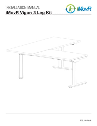
- 1. TCSL180 Rev. B INSTALLATION MANUAL iMovR Vigor: 3 Leg Kit
- 2. 2 Installation Manual: HEIGHT ADJUSTABLE TABLE: Three Leg Kit A M6 x 15 Bolt 8 pieces Tool: 5mm Allen Key B M4 x 25 Phillips Screw 2 pieces Tool: #2 Phillips Screw Driver C M5 x 20 Phillips Screw 35 pieces Tool: #2 Phillips Screw Driver D M10 x 35 Bolt 8 pieces Tool: 5mm Allen Key E Leveler 5 pieces F Set Screw (Pre-Installed) 8 pieces Tool: 4mm Allen Key G M6*8+BW Hex Screw 6 pieces Tool: 4mm Allen Key H M5 x 8 Screw 2 pieces Tool: #2 Phillips Screw Driver I M10 x 20 Bolt 4 pieces Tool: 8mm Allen Key Contents Part List / Hardware List and Tools Required / Warnings/Disclaimer.........................2 Installation Instructions - STEP 1 - STEP 21.................................................... 2 - 8 4-Position Memory Control...................................................................................8 INSTALLATION WARNINGS: • Read the entire instruction manual before beginning any installation or assembly. • Improper installation of this product may cause extensive property damage or serious personal injury, either during or after installation. DISCLAIMER: • The manufacturer will bear no responsibility for any damages of any kind arising from improper installation of this product. • Work surfaces will vary widely and the ultimate method of installing is out of the manufacturers control. It is imperative that the installer consult the work surface installation guide to ensure that it can safely handle the applied load. ADJUSTMENT NOTIFICATION: • Routine maintenance checks and adjustments are suggested to properly support the quality and optimal performance of this product. • Over tightening of bolts during installation or adjustments can damage the product and affect the function and warranty. Hardware List and Tools Required Part List Warnings/Disclaimers A Leg 3 qty. B Feet 2 qty. C Mid Post Base 1 qty. D Outer Frame (Left) 2 qty. E Outer Frame (Right) 2 qty. F Inner Frame 4 qty. G Side Support Bracket (Right) 1 qty. H Side Support Bracket (Left) 1 qty. I Mid Post Frame (Left) 1 qty. J Mid Post Frame (Right) 1 qty. K Mid Post Bracket 1 qty. L Controller 1 qty. M Table Top Support Bracket 1 qty. N Extension Cord 1 qty. O Power Cable 1 qty. P Height Adjustable Controller 1 qty.
- 3. 3Installation Manual: HEIGHT ADJUSTABLE TABLE: Three Leg Kit Installation Instructions STEP 1 Secure PART I & J - Mid Post Frames (Left/Right) to PART A - 1 x Leg with 4 x Screw G. STEP 3 Place PART C - Mid Post Base at the end of PART A - Leg. Secure with 4 x Bolt I. Insert 1x Leveler E to the Mid Post Base. Tighten by hand. (The Leveler can be adjusted to level table surface later.) STEP 2 Secure PART K - Mid Post Bracket to PART I and J with 2 x Screw G. STEP 4 Insert PART F - 2 x Inner Frame into the Mid Post Frame from STEP 2. Use 4 mm Allen Key to tighten. Use 8 mm Allen Key to tighten. Use 4 mm Allen Key to tighten. Screw G PART A - Leg PART I - Mid Post Frame (Left) PART J - Mid Post Frame (Right) PART K - Mid Post Bracket Screw G Bolt I PART C - Mid Post Base Insert the Part D & E - Outer Frames (Left/Right) into PART F - Inner Frame from above. PART F - Inner Frame PART F - Inner Frame PART E - Outer Frame (Right) PART D - Outer Frame (Left)
- 4. 4 Installation Manual: HEIGHT ADJUSTABLE TABLE: Three Leg Kit STEP 5 Repeat STEP 4 on the opposite side. STEP 7 Repeat STEP 6 on the opposite side STEP 6 Attach PART A - 1 x Leg to PART D & E - Outer Frames (Left/Right) from STEP 5 with 2 x Bolt A. STEP 8 Slide PART G & H Side Support Brackets (Left/Right) into the Outer Frame (Left/Right) ends. The brackets must be fully inserted into the frame. A rubber mallet may be needed to complete engagement. Use 5 mm Allen Key to tighten. PART H - Side Support Bracket (Left) PART F - Inner Frame PART F - Inner Frame PART E - Outer Frame (Right) PART D - Outer Frame (Left) Bolt A PART D - Outer Frame (Left) PART E - Outer Frame (Right) PART A - Leg PART A - Leg Bolt A Use 5 mm Allen Key to tighten. PART G - Side Support Bracket (Right) PART D - Outer Frame (Left) PART E - Outer Frame (Right)
- 5. 5Installation Manual: HEIGHT ADJUSTABLE TABLE: Three Leg Kit STEP 9 Lift each PART A - Leg into the final vertical position. STEP 11 Install PART L - Controller between the Inner Frames. Secure with 2 x Screw H. STEP 10 Insert 4 x Bolt A through the sides of the table leg frame to secure the Side Support Brackets. STEP 12 The optional PART M - Table Top Support Bracket should be secured with 8 x Screw C. Use 5 mm Allen Key to tighten. PART M - Table Top Support Bracket PART A - Leg PART A - Leg Bolt A PART L - Controller Screw H Use a #2 Phillips Screwdriver to tighten. Use a #2 Phillips Screwdriver to tighten. Screw C
- 6. 6 Installation Manual: HEIGHT ADJUSTABLE TABLE: Three Leg Kit STEP 13 Connect PART P - Height Adjustment Controller to PART L - Controller. STEP 15 Connect all 3 Leg cables to the Controller. STEP 14 Connect PART N - Extension Cord to the farthest PART A - Leg from the PART L - Controller. STEP 16 Connect PART O - Power Cable to the Controller. PART L - Controller PART L - Controller PART N - Extension Cord PART A - Leg Cable from Part A PART O - Power Cable PART P - Height Adjustable Controller
- 7. 7Installation Manual: HEIGHT ADJUSTABLE TABLE: Three Leg Kit STEP 17 Adjust the frame to fit the table top. STEP 19 Tighten the 8 x Pre-Installed Set Screw F on the inner side of the table leg frame. STEP 18 Secure the table frame to the table top using 27 x Screw C. STEP 20 Place the table Part B - Feet onto the ends of the legs. (Ensure the feet are facing the correct direction.) Use 8 x Bolt D to secure the feet to the legs. Insert the 4 x Leveler into the bottom of the feet. Tighten until secure. (The Levelers will have to be adjusted once the table is upright to ensure the table is level and stable) Screw F Screw C Screw B Use a #2 Phillips Screwdriver to tighten. Secure the Height Adjustment Controller to the table top using 2 x Screw B. Use 4 mm Allen Key to tighten. Screw D Leveller PART B - Feet PART B - Feet Use 5 mm Allen Key to tighten.
- 8. 8 Installation Manual: HEIGHT ADJUSTABLE TABLE: Three Leg Kit Installation Instructions 4-Position Memory Control RESET ***PERFORM RESET BEFORE 1ST USE*** 1. Press both and buttons at the same time until the table is in its lowest position. 2. The display on the height adjustment controller will show "000" while conducting reset. 3. When height adjustment controller beeps, the buttons can be released and reset is complete. NOTE: If anti-collision feature is activated by table contacting an immovable object, the reset function will need to be performed. NORMAL OPERATION 1. Press any button and the display shows current height in inches (in). 2. Press or button to adjust the height. 3. When no button has been pressed for 30 seconds, the system goes to <0.1 W standby mode, and the display turns off. Press any button to wake the system and display the current base height. CHANGING STARTING HEIGHT 1. The default starting height is approximately 25". 2. To adjust the starting height, press button until reaching lowest position. At the lowest position, press button again for 5 seconds until display starts flashing for 10 seconds. 3. During this time, press or buttons to adjust height to preferred starting position, and then press and buttons together for 3 seconds to store this position. 4. Display stops flashing and the new starting height is shown in the display. SETTING & USING MEMORY PRESET POSITIONS 1. Operate the desk to preferred height. 2. Press any of ①②③④ together with or for 2 seconds to store the current height. Display shows P1/P2/P3/P4 when the position has been stored. 3. To return table/desk to a stored position, hold the memory preset button ①②③④ until the desk reaches the stored height. 4. Memory presets can be overwritten with a new position at any time. 1 2 3 4 1 2 3 4 TCSL180 Rev. B STEP 21 Flip the table over. Reset the 4-Position Memory Controller before use.