Lc3519051910
•
0 likes•266 views

International Journal of Engineering Research and Applications (IJERA) is an open access online peer reviewed international journal that publishes research and review articles in the fields of Computer Science, Neural Networks, Electrical Engineering, Software Engineering, Information Technology, Mechanical Engineering, Chemical Engineering, Plastic Engineering, Food Technology, Textile Engineering, Nano Technology & science, Power Electronics, Electronics & Communication Engineering, Computational mathematics, Image processing, Civil Engineering, Structural Engineering, Environmental Engineering, VLSI Testing & Low Power VLSI Design etc.

Recommended
Recommended
More Related Content
What's hot
What's hot (18)
Similar to Lc3519051910
Similar to Lc3519051910 (20)
Recently uploaded
Recently uploaded (20)
Lc3519051910
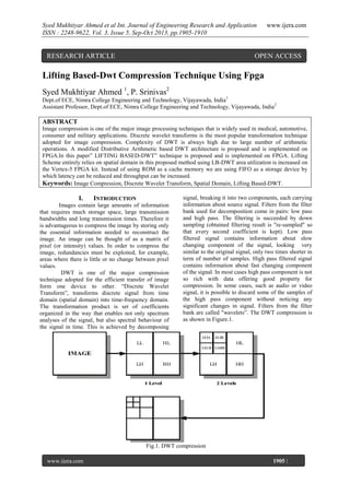
- 1. Syed Mukhtiyar Ahmed et al Int. Journal of Engineering Research and Application ISSN : 2248-9622, Vol. 3, Issue 5, Sep-Oct 2013, pp.1905-1910 RESEARCH ARTICLE www.ijera.com OPEN ACCESS Lifting Based-Dwt Compression Technique Using Fpga Syed Mukhtiyar Ahmed 1, P. Srinivas2 Dept.of ECE, Nimra College Engineering and Technology, Vijayawada, India 1 Assistant Professor, Dept.of ECE, Nimra College Engineering and Technology, Vijayawada, India 2 ABSTRACT Image compression is one of the major image processing techniques that is widely used in medical, automotive, consumer and military applications. Discrete wavelet transforms is the most popular transformation technique adopted for image compression. Complexity of DWT is always high due to large number of arithmetic operations. A modified Distributive Arithmetic based DWT architecture is proposed and is implemented on FPGA.In this paper” LIFTING BASED-DWT” technique is proposed and is implemented on FPGA. Lifting Scheme entirely relies on spatial domain in this proposed method using LB-DWT area utilization is increased on the Vertex-5 FPGA kit. Instead of using ROM as a cache memory we are using FIFO as a storage device by which latency can be reduced and throughput can be increased. Keywords: Image Compression, Discrete Wavelet Transform, Spatial Domain, Lifting Based-DWT. I. INTRODUCTION Images contain large amounts of information that requires much storage space, large transmission bandwidths and long transmission times. Therefore it is advantageous to compress the image by storing only the essential information needed to reconstruct the image. An image can be thought of as a matrix of pixel (or intensity) values. In order to compress the image, redundancies must be exploited, for example, areas where there is little or no change between pixel values. DWT is one of the major compression technique adopted for the efficient transfer of image form one device to other. “Discrete Wavelet Transform”, transforms discrete signal from time domain (spatial domain) into time-frequency domain. The transformation product is set of coefficients organized in the way that enables not only spectrum analyses of the signal, but also spectral behaviour of the signal in time. This is achieved by decomposing signal, breaking it into two components, each carrying information about source signal. Filters from the filter bank used for decomposition come in pairs: low pass and high pass. The filtering is succeeded by down sampling (obtained filtering result is "re-sampled" so that every second coefficient is kept). Low pass filtered signal contains information about slow changing component of the signal, looking very similar to the original signal, only two times shorter in term of number of samples. High pass filtered signal contains information about fast changing component of the signal. In most cases high pass component is not so rich with data offering good property for compression. In some cases, such as audio or video signal, it is possible to discard some of the samples of the high pass component without noticing any significant changes in signal. Filters from the filter bank are called "wavelets”. The DWT compression is as shown in Figure.1. Fig.1. DWT compression www.ijera.com Page 1905 |
- 2. Syed Mukhtiyar Ahmed et al Int. Journal of Engineering Research and Application ISSN : 2248-9622, Vol. 3, Issue 5, Sep-Oct 2013, pp.1905-1910 II. EXISTING TECHNIQUE 2.1. Distributive Arithmetic-DWT “Discrete Wavelet Transform” consists of complexities due to huge arithmetic operations in the image compression to overcome these complexities DA-DWT technique is designed in which consists of four “Look Up Tables” (LUTs), each of the LUTs are accessed by the even and odd samples of input matrix simultaneously. Odd and even input samples are divided into 4 bits of LSB and 4 bits of MSB, each 4bit data read the content of four different LUTs that consist of partial products of filter values computed and stored as per the DA logic. Input samples are split into even and odd in the first stage, the data is further loaded sequentially into the serial in serial out shift registers, top four shift register store MSB bits and bottom four shift register stores the LSB bits. It www.ijera.com requires 40 clocks cycles to load the shift register contents. At the end of 40th clock cycle, the control logic configures the shift register as serial in parallel out, thus forming the address for the LUT. The partial products stored in the LUT are read simultaneously from all the four LUTS and are accumulated with previous values available across the shift register in the output stage. The output stage consisting of adders, accumulators and right shift registers are used to accumulate the LUT contents and thus compute the DWT output. This architecture has a latency of 44 clock cycles in computing the first high pass and low pass filter coefficients, and has a through put of 4 clock cycles. The block representation of DA-DWT technique is as shown in below Figure.2. Fig.2.Distributive Arithmetic-DWT technique III. PROPOSED TECHNIQUE Lifting Based Technique The lifting scheme is a new method to construct wavelet basis, which was first introduced by Swelden’s. The lifting scheme entirely relies on the spatial domain, has many advantages compared to filter bank structure, such as lower area, power consumption and computational complexity. The lifting scheme can be easily implemented by hardware due to its significantly reduced computations. Lifting has other advantages, such as “in-place” computation of the DWT; integer-to-integer wavelet transforms which are useful for lossless coding. The lifting scheme has been developed as a flexible tool suitable for constructing the second generation wavelets. It is composed of three basic operation stages: split, predict and update. Fig.3. shows the lifting scheme of the 3.1. www.ijera.com Page wavelet filter computing one dimension signal. The three basic steps in Lifting based DWT are: Split step: where the signal is split into even and odd points, because the maximum correlation between adjacent pixels can be utilized for the next predict step. For each pair of given input samples x (n) split into even x (2n) and odd coefficients x (2n+1). Predict step: The even samples are multiplied by the predict factor and then the results are added to the odd samples to generate the detailed coefficients (dj).Detailed coefficients results in high pass filtering. Update step: The detailed coefficients computed by the predict step are multiplied by the update factors and then the results are added to the even samples to 1906 |
- 3. Syed Mukhtiyar Ahmed et al Int. Journal of Engineering Research and Application ISSN : 2248-9622, Vol. 3, Issue 5, Sep-Oct 2013, pp.1905-1910 get the coarse coefficients (sj).The coarser coefficients gives low pass filtered output. www.ijera.com The basic block represent of the Lifting Based-DWT is as shown in below Figure.3.1.1. Fig.3.1.1.Basic block for Lifting Based technique In our proposal technique we are constructing the 1D-DWT block using basic block of Lifting Based technique in which the input value is stored in every storage device “D” and then it is given to accumulator as an input with feedback then it is again stored in the memory storage which is temporary. External coefficients are given to the multiplier as input with the previous storage memory output as input to multiplier, these two inputs are multiplied then result is stored in another temporary storage memory. Then all these multipliers output is given to accumulator to sum all these coefficients and then it is given to permanent memory device. The block representation is as shown in below Figure.3.1.2. Fig.3.1.2.1D-DWT Lifting Based technique This block represent is only for 1D-DWT Lifting Based technique for row operation .The obtained outputs is given as input to do column operation then we get 2D-DWT Lifting Based technique. Using this model we can increase the area utilization. www.ijera.com Page 3.2 Using FIFO instead of ROM as a cache memory In DA-DWT we have disadvantages of area utilization, latency, and throughput. Using Lifting Based technique we overcome the problem of area utilization but the throughput and latency is the major problem in referred technique, to overcome this 1907 |
- 4. Syed Mukhtiyar Ahmed et al Int. Journal of Engineering Research and Application ISSN : 2248-9622, Vol. 3, Issue 5, Sep-Oct 2013, pp.1905-1910 problem we are replacing the memory storage device form ROM to FIFO. Instead of using ROM using FIFO my have an advantage, here using ROM only one operation is done in one clock cycle where as using “First In First Out” technique simultaneously two commands can be operated in single clock pulse. The commands such as read and write, these both can be done in single clock pulse only by which the latency can be reduced and we can obtain high throughput. IV. www.ijera.com The developed model is simulated using test bench. The HDL model is synthesized using Xilinx ISE targeting Vertex 5-pro FPGA. The proposed design is implemented and the synthesis report is generated. The results obtained are presented in Table as shown below. The proposed design implemented on FPGA occupies 12% of the total slices on FPGA, thus the proposed architecture has the higher area utilization and throughput. Thus the synthesis report is as shown below in table.1. FPGA Implementation Table.1.Synthesis Report V. VERIFICATION OF RESULTS The whole design of Lifting Based technique is simulated using XILINX software. 5.1. Area Utilization Using Lifting Based Simulation Results www.ijera.com Page Simulation results for the proposed design is as shown in the below Figures 5.1. Using this technique we have increased the area utilization on the VERTEX 5 FPGA as twice the existing technique. 1908 |
- 5. Syed Mukhtiyar Ahmed et al Int. Journal of Engineering Research and Application ISSN : 2248-9622, Vol. 3, Issue 5, Sep-Oct 2013, pp.1905-1910 www.ijera.com Fig.5.1.Lifting Based-DWT Output 5.2. Simulation Result of Using FIFO Instead of using ROM as a memory we have used “First In First Out” technique as an cache memory to overcome the through and latency problem. From the output we can see that for one clock cycle both read and write operations are done through which throughput is increased as the latency decreased. The simulation result is as shown in below Figure5.2. Fig.5.2.FIFO Output www.ijera.com Page 1909 |
- 6. Syed Mukhtiyar Ahmed et al Int. Journal of Engineering Research and Application ISSN : 2248-9622, Vol. 3, Issue 5, Sep-Oct 2013, pp.1905-1910 VI. CONCLUSION In this paper, we proposed a design of Lifting Based technique. In this area utilization is more than the existing model and the synthesis report says that the logical utilization of Lifting Based technique is twice that of the existing technique on the VERTEX 5 FPGA. Instead of ROM we have used FIFO to increase the throughput. Hope this Lifting Based technique meets the modern compression needs. The design has great flexibility, high integration. Because of using FIFO data loss is avoid. VII. FUTURE WORK [7] [8] [9] www.ijera.com Ali M. Al-Haj “Fast Discrete Wavelet Transformation Using FPGAs andDistributed Arithmetic” International Journal of Applied Science and Engineering 2003. 1, 2: 160-171. S.Masud"VLSI system for discrete wavelet transforms", PhD Thesis, Dept. of electrical engineering, The Queen’s University of Belfast, 1999. G.R.Shruti,V.Prabhu“Low Power And High Speed Encoder Using Lossless Image Compression” MASAUM Journal of Open Problems in Science and Engineering, Vol.1, No.1, October 2009. In this paper, we have overcome and modified the existing technique. By using Lifting Based technique in which the number of inputs are more given to each filter by which the efficiency can be reduced. The main disadvantage is the power utilization is more in proposed technique. These must be overcome in future work. VIII. ACKNOWLEDGEMENTS I am glad to express my deep sense of gratitude to Mr.P.Srinivas, Assistant Professor, Electronic and Communication Engineering .Nimra College of Science and Technology, for their great support and encouragement in completion of this paper. REFERENCES [1] [2] [3] [4] [5] [6] Pipelinined Distributive Arithmetic based Discrete Wavelet Transform IP core", EJSR, Vol . 35, No. 3, pp. 378-392,2010. MajidRannani and Rajan Joshi, "An Overview of the JPEG2000 Still Image Compression Standard", Signal Processing, Image Communication, vol. 17, pp. 3-48, 2010. David S. Taubman, Michael W. Marcellin – “JPEG 2000 – Image compression, fundamentals, standards Nagabushanam, Cyril Prasanna Raj P, Ramachandran, "Design and implementation of Parallel and and practice", Kluwer academic publishers, Second printing – 2009. C. Chakrabarti and M. Vishwanath, "Architectures for Wavelet Transforms: A Syrvey", Journal of VLSI Signal Processing, Kulwervol.lO, pp. 225-236,2007. Daubechies, W. Sweldens,(1998), “ Factoring wavelet transform into lifting steps”, J. Fourier Anal. Appl. 4, 247–269. Chao Cheng and Keshab K. Parhi,(2008), “.High-Speed VLSI Implementation of 2-D Discrete Wavelet Transform”,IEEE Transactions on Signal Processing, Vol. 56, No. 1. www.ijera.com Page 1910 |