SlideShare a Scribd company logo
1 of 6
Download to read offline
Rakesh Kumar, Anjum Sharma / International Journal of Engineering Research and Applications
                      (IJERA) ISSN: 2248-9622 www.ijera.com
                       Vol. 2, Issue 4, July-August 2012, pp.906-911

     Fault Tolerance for Chain based Hierarchical Data Gathering
                          Protocol for WSN
              Rakesh Kumar                                                Anjum Sharma

Abstract
         Wireless sensor network nodes are very          inaccessible terrains or disaster relief operations. On
tiny in size and their cost is also not very high.       the other hand, this also means that sensor network
They are deployed in any geographical region in a        protocols and algorithms must possess self
random fashion. During the process of data               organizing capabilities. Instead of sending the raw
sensing, data gathering and data transmission, the       data to the nodes responsible for the fusion, they use
charge of the power unit associated with any node        their processing abilities to locally carry out simple
gets low, after certain time, i.e., each node has its    computations and transmit only the required and
life time. The life time of nodes directly affects the   partially processed data. The above described
life time of the sensor network. As each node is         features ensure a wide range of applications for
very low in cost, it is unnecessary and difficult too,   sensor networks. Some of the application areas are
to recharge them once their energies are                 health, military, and home. In military, for example,
exhausted. Therefore, it is very important to            the rapid deployment, self-organization, and fault
conserve the power of the nodes so that the life         tolerance characteristics of sensor networks make
time of the entire network can be conserved.             them a very promising sensing technique for military
Hence the requirement of a power efficient data          command, control, communications, computing,
gathering protocol is very important to serve the        intelligence, surveillance, reconnaissance, and
purpose in wireless sensor network. In the               targeting systems. In health, sensor nodes can also be
proposed work, it is being tried to change the idea      deployed to monitor patients and assist disabled
relating to the data gathering and transmission of       patients. Some other commercial applications include
the existing model, as, chain leaders belonging to       managing inventory, monitoring product quality, and
certain covering angle will only transmit the            monitoring disaster areas.
gathered data to the another chain leader of the
same covering angle and we have implemented the
backup chain leader as a fault tolerance
mechanism . Our research can provide better
efficiency and resource consumption and further
can provide good level of fault tolerance.

Keywords: Wireless Sensor Node, Cluster, Cluster
Head, Fault tolerance

1.      INTRODUCTION
         Recent       advances       in      wireless
communications and electronics have enabled the
                                                         Figure 1: Sensor nodes scattered in a sensor field
development of low-cost, low power, multifunctional
sensor nodes that are small in size and communicate      The sensor nodes are usually scattered in a sensor
unmetered in short distances. These tiny sensor          field as shown in Figure1.Each of these scattered
nodes, which consist of sensing, data processing, and    sensor nodes has the capabilities to collect data and
communicating components, leverage the idea of           route data back to the sink. Data are routed back to
sensor networks. Sensor networks represent a             the sink by a multi-hop infrastructure less
significant improvement over traditional sensors. A      architecture through the sink as shown in Figure1.
sensor network is composed of a large number of
                                                         The sink may communicate with the task manager
sensor nodes that are densely deployed either inside
                                                         node via Internet or satellite. The design of the sensor
the phenomenon or very close to it. The position of
                                                         network as described by Figure1 is influenced by
sensor nodes need not be engineered or
                                                         many factors, including fault tolerance, scalability,
predetermined. This allows random deployment in
                                                         production costs, operating environment, sensor

                                                                                                 906 | P a g e
Rakesh Kumar, Anjum Sharma / International Journal of Engineering Research and Applications
                      (IJERA) ISSN: 2248-9622 www.ijera.com
                       Vol. 2, Issue 4, July-August 2012, pp.906-911
network topology, hardware constraints, transmission      protocols utilize position information to relay the data
media, and power consumption.                             to the desired regions rather than the whole network.
2. ROUTING TECHNIQUES IN WSN                              3. RELATED WORK
         Wireless sensor networks (WSN) consist of                 In general, three strategies are considered
small nodes with sensing, computation, and wireless       for the design of data aggregation techniques in
communications capabilities. Many routing, power          WSNs. They are cluster based, tree-based, and chain-
management, and data dissemination protocols have         based . In this section, we only review three chain-
been specifically designed for WSNs where energy          based routing protocols, PEGASIS, COSEN, and
awareness is an essential design issue. Routing           Enhanced PEGASIS, and point out their pros and
protocols in WSNs might differ depending on the           cons that motivate our research.
application and network architecture. Overall, the
routing techniques are classified into three categories   A. PEGASIS
based on the underlying network structure: flat,
                                                                   PEGASIS is a basic chain-based routing
hierarchical,     and     location-based       routing.
                                                          protocol. In which, all nodes in the sensing area are
Furthermore, these protocols can be classified into
                                                          first organized into a chain by using a greedy
multipath-based, query-based, negotiation based,
QoS-based, and coherent based depending on the            algorithm, and then take turns to act as the chain
protocol     operation.   Many       routing,    power    leader. In data dissemination phase, every node
                                                          receives the sensing information from its closest
management, and data dissemination protocols have
                                                          upstream neighbour, and then passes its aggregated
been specifically designed for WSNs where energy
                                                          data toward the designated leader, via its downstream
awareness is an essential design issue. Routing
protocols in WSNs might differ depending on the           neighbour, and finally the base station. Although the
application and network architecture. Overall, the        PEGASIS constructs a chain connecting all nodes to
                                                          balance network energy dissipation, there are still
routing techniques are classified into three categories
                                                          some flaws with this scheme. 1) For a large sensing
based on the underlying network structure: flat,
                                                          field and real-time applications, the single long chain
hierarchical,     and     location-based       routing.
                                                          may introduce an unacceptable data delay time. 2)
Furthermore, these protocols can be classified into
multipath-based, query-based, and negotiation-based,      Since the chain leader is elected by taking turns, for
QoS based, and coherent based depending on the            some cases, several sensor nodes might reversely
                                                          transmit their aggregated data to the designated
protocol operation. Figure 2 shows routing protocols
                                                          leader, which is far away from the BS than itself.
in WSNs.
                                                          This will result in redundant transmission paths, and
                                                          therefore seriously waste network energy. 3) The
                                                          single chain leader may become a bottleneck.
                                                          B. COSEN
                                                                    In contrast to PEGASIS, COSEN is a two-
                                                          tier hierarchical chain-based routing scheme. In that
                                                          scheme, sensor nodes are geographically grouped
                                                          into several low-level chains. For each low-level
                                                          chain, the sensor node with the maximum residual
                                                          energy is elected as the chain leader. Moreover, with
                                                          the low-level leaders, a high-level chain and its
                                                          corresponding chain leader will be eventually
                                                          formulated. In data communications, all common
                                                          (normal) nodes perform a similar procedure as that in
                                                          PEGASIS to send their fused data, via their
                                                          respective low-level leaders and the high-level leader,
                                                          toward the BS. COSEN, compared to PEGASIS,
Figure 2: Routing Protocols in WSNs                       although can alleviate the transmission delay and
                                                          energy consumption, it still introduces a lot of
In flat networks all nodes play the same role, while
                                                          redundant transmission paths, especially for those
hierarchical protocols aim to cluster the nodes so that
                                                          nodes which are nearest to the BS but would detour
cluster heads can do some aggregation and reduction
                                                          their fused data toward the farther leaders.
of data in order to save energy. Location-based


                                                                                                  907 | P a g e
Rakesh Kumar, Anjum Sharma / International Journal of Engineering Research and Applications
                      (IJERA) ISSN: 2248-9622 www.ijera.com
                       Vol. 2, Issue 4, July-August 2012, pp.906-911
C. Enhanced PEGASIS                                                definition of R, different integers (1 … n)
                                                                   are used to indicate distinct angles.
           In 2007, Jung et al. proposed a variation of
PEGASIS routing scheme, termed as Enhanced                        Gθ, R : the group id. Theoretically, by
PEGASIS. In their method, the sensing area, centered               changing different values of θ and R, the
at the BS, is circularized into several concentric                 sensing area can be divided into n * n
cluster levels. For each cluster level, based on the               groups. Those are G1, 1, G1, 2, …, G1, n,
greedy algorithm of PEGASIS, a node chain is                       …, Gn, 1, …, Gn,, n.
constructed. In data transmission, the common nodes
also conduct a similar way as the PEGASIS to                      ni: the node i; the node set N={n1, n2, n3,
transfer their sensing data to its chain leader. After             …, ni}, where 1≤i≤|N|.
that, from the highest (farthest) cluster level to the            cx,y: the id of a chain which was formed in
lowest (near to the BS), a multi-hop and leader-by-                group Gx,y. the chain set C={c1,1, c1,2,
leader data propagation task will be followed. The                 ….}.
EPEGASIS although has considered the location of
the BS to slightly improve the redundant transmission             lx,y: the leader node id of chain cx,y. The
path and the network lifetime, there are still some                leader set L={l1,1, l1,2, ….}.
problems with that scheme. 1) For large sensing                   neighbour(ni): the neighbouring nodes of
areas, the node chain in each concentric cluster would             ni. The neighbouring nodes mean the nodes
still become lengthy, and thus result in a longer                  which are locating in the transmission range
transmission delay. 2) Since the leader node election              of a specific node.
strategy is same as that in PEGASIS (by taking
turns), it did not consider the node’s residual energy.           dis(x, y): the distance between nodes x and
As a node with the least residual energy is elected to             y. The BS can be deemed as a special
act as the leader, the network lifetime would be                   sensor node.
significantly affected. 3) While the distribution of
                                                          B. OPERATION OF CHIRON
sensor nodes is not even, the transmission distance
between two chain-leaders in different cluster levels             The operation of CHIRON protocol consists
might be lengthy, this would consume more energy.         of four phases: 1) Group Construction Phase. 2)
                                                          Chain Formation Phase. 3) Leader Node Election
4. CHIRON PROTOCOL                                        Phase. and 4) Data Collection and Transmission
                                                          Phase.
        For improving the deficiencies with the
aforementioned three schemes, in this section, we         1. Group Construction Phase
thus propose an energy efficient hierarchical chain-      The main purpose of this phase is ready to divide the
based routing protocol, termed as CHIRON. The             sensing field into a number of smaller areas so that
design philosophy is described as follows.                the CHIRON can create multiple shorter chains to
A. Network model and assumptions                          reduce the data propagation delay and redundant
                                                          transmission path in later phases. Instead of using
         Without loss of generality, in our research,     concentric clusters as EPEGASIS scheme does, the
we also consider a WSN of n energy-constrained            CHIRON adopts the technique of Beam Star to
sensor nodes, which are randomly deployed over a          organize its groups. After the sensor nodes are
sensing field. The BS is located at a corner of the       scattered, the BS gradually sweeps the whole sensing
sensing area, and equipped with a directional antenna     area, by successively changing different transmission
and unlimited power. As a result, the BS can              power levels and antenna directions, to send control
adaptively adjust its transmission power level and        information (including the values of R and θ) to all
antenna direction to send control packets to all nodes    nodes. After all nodes receiving such control packets,
in the WSN. Besides, for easy discussion, we define       they can easily determine which group they are
some notations as follows:                                respectively belonging to. In addition, by the received
        R: the transmission range of the BS. For         signal strength indication (RSSI), every node can also
         simplicity, we use distinct integers (1 … n)     figure out the value of dis(ni, BS). A grouping
         to represent various ranges.                     example with R=1...3 and θ=1..2 is shown in Figure
                                                          3.
        θ: the beam width (covering angle) of the
         directional antenna. Also, similar to the


                                                                                                 908 | P a g e
Rakesh Kumar, Anjum Sharma / International Journal of Engineering Research and Applications
                      (IJERA) ISSN: 2248-9622 www.ijera.com
                       Vol. 2, Issue 4, July-August 2012, pp.906-911


      Fig. 3 Grouping example with R=1…3 and
θ=1...2


2. Chain Formation Phase
In this phase, the nodes within each group Gx,y will
be linked together to form a chain cx,y, respectively.
The chain formation process is same as that in            Figure 4: The group chains constructed from Figure 1
PEGASIS scheme. For each group Gx,y, the node ni
with the maximum value of dis(ni, BS) (that is
farthest away from the BS) is initiated to create the
group chain. By using a greedy algorithm, the nearest
node (to ni) of neighbor(ni) will be chosen to link the
node ni, and become as the newly initiate node in
next linking step. The process is repeated until all
nodes are put together, and thus finally a group chain
cx,y is formed. Figure 2 shows all group chains that
are constructed from the sensing environment of
Figure 2
3. Leader Node Election Phase
For data transmission, a leader node in each group
chain must be selected for collecting and forwarding      Figure 5: The data transmission flows
the aggregated data to the BS. Unlike the PEGASIS
and EPEGASIS schemes, in which the leader in each
chain is elected in a round-robin manner, CHIRON          4. Data Collection and Transmission Phase
chooses the chain leader (lx,y) based on the
maximum value Res(ni) of group nodes. Initially, in       After completed the previous three phases, the data
each group, the node farthest away from the BS is         collection and transmission phase begins. The data
assigned to be the group chain leader. After that, for    transmission procedure in CHIRON is similar to that
each data transmission round, the node with the           in PEGASIS scheme. Firstly, the normal nodes in
maximum residual energy will be elected. The              each group Gx,y transmit their collected data along
residual power information of each node ni can be         the cx,y, by passing through their nearest nodes, to
piggybacked with the fused data to the chain leader       the chain leader lx,y. And then, starting from the
lx,y along the chain cx,y, so that the chain leader can   farthest groups, the chain leaders collaboratively
determine which node will be the new leader for next      relay their aggregated sensing information to the BS,
transmission round.                                       in a multi-hop, leader-by-leader transmission manner.
                                                          In order to avoid a longer transmission distance
                                                          incurred between two chain leaders, and thus result in
                                                          a great amount of energy dissipation,


                                                                                                  909 | P a g e
Rakesh Kumar, Anjum Sharma / International Journal of Engineering Research and Applications
                      (IJERA) ISSN: 2248-9622 www.ijera.com
                       Vol. 2, Issue 4, July-August 2012, pp.906-911

5. IMPROVED CHIRON SCHEMES                                changes in angles due to the sensing elements . Due
                                                          to this sensing the time and power.
          CHIRON is used to split the sensing field
into a number of smaller areas, so that it can create
multiple shorter chains to reduce the data                                                          4
                                                                                                                     chiron vs improve
                                                                                                x 10
transmission delay and redundant path, and therefore                                       2
                                                                                                                                                         chiron
effectively conserve the node energy and prolong the                                      1.8                                                            improve
network lifetime. In CHIRON routing is done on the                                        1.6
basis of angles. As the routing start from the                                            1.4
clusterhead to destination the path changes in angles
                                                                                          1.2
due to the sensing elements . Due to this sensing the


                                                                   y(data)
time and power dissipation increases hence the                                             1

CHIRON has not exact output, when we compare to                                           0.8

the real applications. In proposed schemes                                                0.6
communication, routing is done between clusterhead                                        0.4
(CH) to clusterhead (CH) is done directly or as a
                                                                                          0.2
straight line. In proposed scheme network is divide
                                                                                           0
into two parts, so only two sensor element are                                                  0       500   1000         1500          2000     2500         3000
                                                                                                                          x(time)
present between two clusterheads (CHs). Hence we
have two straight path for routing. Since the number      (a)
of sensor elements are reduced so sensing time and
power dissipation are reduced hence the                                          9000
                                                                                                                      chiron vs improve

improvement in CHIRON is possible.                                                                                                                         chiron
                                                                                 8000                                                                      improve

                                                                                 7000

6. SIMULATION AND RESULTS                                                        6000


         For evaluation the performance and fault
                                                            y(balance)


                                                                                 5000

tolerance of our proposed CHIRON protocol, in this                               4000
section, we use a simulation tool MATLAB to
                                                                                 3000
conduct several experiments
                                                                                 2000
A. Simulation environment and parameters
                                                                                 1000
          In our simulations, we consider three
                                                                                            0
different sizes of sensing area: 100 m*100 m, 200                                              0       500    1000          1500          2000     2500           3000
                                                                                                                            x(time)
m*200 m, and 300 m*300 m, each is with 100
randomly deployed sensor nodes. The BS is located         (b)
on the corner of sensing field. Every sensor node is
initially equipped with 0.5 joules power. We define
the average delay ass the average required hops, and                                                                 chiron vs improve
the redundant transmission path as the number of                                          15
                                                                                                                                                         chiron
detour hops, for one node transmits its sensing data to                                                                                                  improve
the BS, respectively. We also define the simulation
round as a duration time in which all sensor nodes
sent a 2000-bit packet to the BSS. For each                                               10
                                                                         y(distributed)


simulation scenario, the results are drawn by the
average value of 10 runs.
B. Simulation results                                                                      5

         Figure 6 shows the simulation results of
average     propagation    delay     and    redundant
transmission path for two compared schemes. It
could be seen that the proposed scheme. In CHIRON                                          0
                                                                                                0       500   1000         1500          2000     2500         3000
routing is done on the basis of angles. As the routing                                                                    x(time)

start from the cluster-head to destination the path
                                                          (c)

                                                                                                                                                910 | P a g e
Rakesh Kumar, Anjum Sharma / International Journal of Engineering Research and Applications
                      (IJERA) ISSN: 2248-9622 www.ijera.com
                       Vol. 2, Issue 4, July-August 2012, pp.906-911
Figure 6: Improved results for CHIRON.(a) Graph            [3]   C. Y. Chong and S. P. Kumar, “Sensor
for data on network. (b) Graph for balancing of data             Networks: Evolution, Opportunities, and
on network. (c) Graph for distribution of data on                Challenges,” Proceedings of the IEEE, Vol.
network.                                                         91, pp. 1247-1256, 2003.
         These graph shows the improved result for         [4]   W. R. Heinzelman, A. Chandrakasan, and H.
CHIRON, in which Figure 6.a) shows the data                      Balakrishnan,      “Energy      Efficient
process on the network even when the energy is get               Communication Protocol for Wireless
zero. Figure 6.b) shows the balancing of traffic using           Microsensor Networks,” Proceedings of the
the imroved CHIRON and CHIRON. Improved                          33rd Hawaii International Conference on
schemes shows the balancing improvement over                     System Sciences, 2000.
CHIRON. Figure 6.c) shows the distributing of traffic
                                                           [5]   W. R. Heinzelman, A. Chandrakasan, and H.
using     the imroved CHIRON and CHIRON.
                                                                 Balakrishnan, “An Application Specific
Improved     schemes     shows     the    distributing
                                                                 Protocol    Architecture  for   Wireless
improvement over CHIRON.
                                                                 Microsensor Networks,” IEEE Transaction
                                                                 on Wireless Commun. Vol. 1, Issue 4, pp.
                                                                 660-670, 2002.
7. CONCLUSION
                                                           [6]   E. Altman, T. Basar, T. Jimenez, and N.
          In this paper, we discuss an efficient                 Shimkin, “Competitive routing in networks
hierarchical chain based routing protocol CHIRON,                with polynomial costs,” IEEE Trans.
which is suitable for large sensor networks with                 Automat. Control, vol. 47, no. 1, pp. 92-96,
power and time constraints. In our approaches, we                2002.
utilize the concept of Beam Star topology to divide
the whole sensing field into a number of smaller           [7]   J. Choi, C. Conrad, C. Malakowsky, J.
areas, so that the CHIRON can create multiple                    Talent, C.S. Yuan, and R.W. Gracy,
shorter chains to reduce the data propagation delay              “Flavones from Scutellaria baicalensis
and redundant transmission path and provide better               Georgi attenuate apoptosis and protein
fault tolerance, thus significantly save network                 oxidation in neuronal cell lines,”
energy. dissipation increases. Hence the CHIRON                  Biochemica et Biophysica Acta, 1571: 201-
has not exact output when we compare to the real                 210 (2002).
applications. In proposed schemes communication,
routing is done       between clusterhead (CH) to
clusterhead (CH) is done directly or as a straight line.
In proposed scheme network is divide into two parts
so only two sensor element are present between two
clusterheads (CHs). Hence we have sequential
straight path for routing. Since the number of sensor
elements are reduced so sensing time and power
dissipation are reduced.


REFERENCES
  [1]    I.   F.    Akyildiz,   W.      Su,    Y.
         Sankarasubramaniam, and E. Cayirci, “A
         Survey on Sensor Networks,” IEEE
         Commun. Mag. Vol. 38, pp. 102-114, 2002.
  [2]    J. N. Al-Karaki and A. E. Kamal, “Routing
         Techniques in Wireless Sensor Networks: A
         Survey,” Proceedings of the IEEE Wireless
         Communications, Vol. 11, pp. 6-28, 2004.


                                                                                              911 | P a g e

More Related Content

What's hot

ROUTING WIRELESS SENSOR NETWORKS BASED ON SOFT COMPUTING PARADIGMS: SURVEY
ROUTING WIRELESS SENSOR NETWORKS BASED ON SOFT COMPUTING PARADIGMS: SURVEYROUTING WIRELESS SENSOR NETWORKS BASED ON SOFT COMPUTING PARADIGMS: SURVEY
ROUTING WIRELESS SENSOR NETWORKS BASED ON SOFT COMPUTING PARADIGMS: SURVEYijscai
 
Report on I-LEACH: An Energy Efficient Routing Protocol in Wireless Sensor Ne...
Report on I-LEACH: An Energy Efficient Routing Protocol in Wireless Sensor Ne...Report on I-LEACH: An Energy Efficient Routing Protocol in Wireless Sensor Ne...
Report on I-LEACH: An Energy Efficient Routing Protocol in Wireless Sensor Ne...divya_prabha
 
Node clustering in wireless sensor
Node clustering in wireless sensorNode clustering in wireless sensor
Node clustering in wireless sensorambitlick
 
Wireless sensor network lifetime constraints
Wireless sensor network lifetime constraintsWireless sensor network lifetime constraints
Wireless sensor network lifetime constraintsmmjalbiaty
 
LOAD BALANCED CLUSTERING WITH MIMO UPLOADING TECHNIQUE FOR MOBILE DATA GATHER...
LOAD BALANCED CLUSTERING WITH MIMO UPLOADING TECHNIQUE FOR MOBILE DATA GATHER...LOAD BALANCED CLUSTERING WITH MIMO UPLOADING TECHNIQUE FOR MOBILE DATA GATHER...
LOAD BALANCED CLUSTERING WITH MIMO UPLOADING TECHNIQUE FOR MOBILE DATA GATHER...Munisekhar Gunapati
 
Cluster-based Target Tracking and Recovery Algorithm in Wireless Sensor Network
Cluster-based Target Tracking and Recovery Algorithm in Wireless Sensor NetworkCluster-based Target Tracking and Recovery Algorithm in Wireless Sensor Network
Cluster-based Target Tracking and Recovery Algorithm in Wireless Sensor NetworkIJASCSE
 
Spread Spectrum Based Energy Efficient Wireless Sensor Networks
Spread Spectrum Based Energy Efficient Wireless Sensor NetworksSpread Spectrum Based Energy Efficient Wireless Sensor Networks
Spread Spectrum Based Energy Efficient Wireless Sensor NetworksIDES Editor
 
Wireless sensor network lifetime constraints
Wireless sensor network lifetime constraintsWireless sensor network lifetime constraints
Wireless sensor network lifetime constraintsmmjalbiaty
 
Performance improvement of automated address assignment for path cluster wsn ...
Performance improvement of automated address assignment for path cluster wsn ...Performance improvement of automated address assignment for path cluster wsn ...
Performance improvement of automated address assignment for path cluster wsn ...IAEME Publication
 
Energy efficient node deployment for target coverage in wireless sensor network
Energy efficient node deployment for target coverage in wireless sensor networkEnergy efficient node deployment for target coverage in wireless sensor network
Energy efficient node deployment for target coverage in wireless sensor networkGaurang Rathod
 
IJERD (www.ijerd.com) International Journal of Engineering Research and Devel...
IJERD (www.ijerd.com) International Journal of Engineering Research and Devel...IJERD (www.ijerd.com) International Journal of Engineering Research and Devel...
IJERD (www.ijerd.com) International Journal of Engineering Research and Devel...IJERD Editor
 
IRJET- Energy Optimization in Wireless Sensor Networks using Trust-Aware Rout...
IRJET- Energy Optimization in Wireless Sensor Networks using Trust-Aware Rout...IRJET- Energy Optimization in Wireless Sensor Networks using Trust-Aware Rout...
IRJET- Energy Optimization in Wireless Sensor Networks using Trust-Aware Rout...IRJET Journal
 
Concealed Data Aggregation with Dynamic Intrusion Detection System to Remove ...
Concealed Data Aggregation with Dynamic Intrusion Detection System to Remove ...Concealed Data Aggregation with Dynamic Intrusion Detection System to Remove ...
Concealed Data Aggregation with Dynamic Intrusion Detection System to Remove ...csandit
 
Energy Efficient PEGASIS Routing Protocol in Wireless Sensor Network
Energy Efficient PEGASIS Routing Protocol in Wireless Sensor NetworkEnergy Efficient PEGASIS Routing Protocol in Wireless Sensor Network
Energy Efficient PEGASIS Routing Protocol in Wireless Sensor NetworkIRJET Journal
 

What's hot (17)

ROUTING WIRELESS SENSOR NETWORKS BASED ON SOFT COMPUTING PARADIGMS: SURVEY
ROUTING WIRELESS SENSOR NETWORKS BASED ON SOFT COMPUTING PARADIGMS: SURVEYROUTING WIRELESS SENSOR NETWORKS BASED ON SOFT COMPUTING PARADIGMS: SURVEY
ROUTING WIRELESS SENSOR NETWORKS BASED ON SOFT COMPUTING PARADIGMS: SURVEY
 
Secure and Efficient Transmission Using Jammer and Relay Networks
Secure and Efficient Transmission Using Jammer and Relay NetworksSecure and Efficient Transmission Using Jammer and Relay Networks
Secure and Efficient Transmission Using Jammer and Relay Networks
 
Report on I-LEACH: An Energy Efficient Routing Protocol in Wireless Sensor Ne...
Report on I-LEACH: An Energy Efficient Routing Protocol in Wireless Sensor Ne...Report on I-LEACH: An Energy Efficient Routing Protocol in Wireless Sensor Ne...
Report on I-LEACH: An Energy Efficient Routing Protocol in Wireless Sensor Ne...
 
Node clustering in wireless sensor
Node clustering in wireless sensorNode clustering in wireless sensor
Node clustering in wireless sensor
 
Wireless sensor network lifetime constraints
Wireless sensor network lifetime constraintsWireless sensor network lifetime constraints
Wireless sensor network lifetime constraints
 
LOAD BALANCED CLUSTERING WITH MIMO UPLOADING TECHNIQUE FOR MOBILE DATA GATHER...
LOAD BALANCED CLUSTERING WITH MIMO UPLOADING TECHNIQUE FOR MOBILE DATA GATHER...LOAD BALANCED CLUSTERING WITH MIMO UPLOADING TECHNIQUE FOR MOBILE DATA GATHER...
LOAD BALANCED CLUSTERING WITH MIMO UPLOADING TECHNIQUE FOR MOBILE DATA GATHER...
 
Cluster-based Target Tracking and Recovery Algorithm in Wireless Sensor Network
Cluster-based Target Tracking and Recovery Algorithm in Wireless Sensor NetworkCluster-based Target Tracking and Recovery Algorithm in Wireless Sensor Network
Cluster-based Target Tracking and Recovery Algorithm in Wireless Sensor Network
 
Spread Spectrum Based Energy Efficient Wireless Sensor Networks
Spread Spectrum Based Energy Efficient Wireless Sensor NetworksSpread Spectrum Based Energy Efficient Wireless Sensor Networks
Spread Spectrum Based Energy Efficient Wireless Sensor Networks
 
Wireless sensor network lifetime constraints
Wireless sensor network lifetime constraintsWireless sensor network lifetime constraints
Wireless sensor network lifetime constraints
 
Performance improvement of automated address assignment for path cluster wsn ...
Performance improvement of automated address assignment for path cluster wsn ...Performance improvement of automated address assignment for path cluster wsn ...
Performance improvement of automated address assignment for path cluster wsn ...
 
0512ijdps26
0512ijdps260512ijdps26
0512ijdps26
 
Energy efficient node deployment for target coverage in wireless sensor network
Energy efficient node deployment for target coverage in wireless sensor networkEnergy efficient node deployment for target coverage in wireless sensor network
Energy efficient node deployment for target coverage in wireless sensor network
 
IJERD (www.ijerd.com) International Journal of Engineering Research and Devel...
IJERD (www.ijerd.com) International Journal of Engineering Research and Devel...IJERD (www.ijerd.com) International Journal of Engineering Research and Devel...
IJERD (www.ijerd.com) International Journal of Engineering Research and Devel...
 
IRJET- Energy Optimization in Wireless Sensor Networks using Trust-Aware Rout...
IRJET- Energy Optimization in Wireless Sensor Networks using Trust-Aware Rout...IRJET- Energy Optimization in Wireless Sensor Networks using Trust-Aware Rout...
IRJET- Energy Optimization in Wireless Sensor Networks using Trust-Aware Rout...
 
QoS in WSN thesis
QoS in WSN thesisQoS in WSN thesis
QoS in WSN thesis
 
Concealed Data Aggregation with Dynamic Intrusion Detection System to Remove ...
Concealed Data Aggregation with Dynamic Intrusion Detection System to Remove ...Concealed Data Aggregation with Dynamic Intrusion Detection System to Remove ...
Concealed Data Aggregation with Dynamic Intrusion Detection System to Remove ...
 
Energy Efficient PEGASIS Routing Protocol in Wireless Sensor Network
Energy Efficient PEGASIS Routing Protocol in Wireless Sensor NetworkEnergy Efficient PEGASIS Routing Protocol in Wireless Sensor Network
Energy Efficient PEGASIS Routing Protocol in Wireless Sensor Network
 

Viewers also liked (20)

Mb2420032007
Mb2420032007Mb2420032007
Mb2420032007
 
H24051055
H24051055H24051055
H24051055
 
Hh2412981302
Hh2412981302Hh2412981302
Hh2412981302
 
Fk2410001003
Fk2410001003Fk2410001003
Fk2410001003
 
J24077086
J24077086J24077086
J24077086
 
Ho2413421346
Ho2413421346Ho2413421346
Ho2413421346
 
Fe24972976
Fe24972976Fe24972976
Fe24972976
 
Ia2414161420
Ia2414161420Ia2414161420
Ia2414161420
 
Gv2412201226
Gv2412201226Gv2412201226
Gv2412201226
 
Gs2412041207
Gs2412041207Gs2412041207
Gs2412041207
 
He2412821285
He2412821285He2412821285
He2412821285
 
Gj2411521157
Gj2411521157Gj2411521157
Gj2411521157
 
Hu2413771381
Hu2413771381Hu2413771381
Hu2413771381
 
Fz2410881090
Fz2410881090Fz2410881090
Fz2410881090
 
Gx2412321236
Gx2412321236Gx2412321236
Gx2412321236
 
Gn2411721180
Gn2411721180Gn2411721180
Gn2411721180
 
Hy2414011407
Hy2414011407Hy2414011407
Hy2414011407
 
Diccionario informático
Diccionario informáticoDiccionario informático
Diccionario informático
 
Ejrcicio Presentación mapas conceptuales L Liberal
Ejrcicio Presentación mapas conceptuales   L LiberalEjrcicio Presentación mapas conceptuales   L Liberal
Ejrcicio Presentación mapas conceptuales L Liberal
 
Los tres pilares de una StartUp y su lanzamiento
Los tres pilares de una StartUp y su lanzamientoLos tres pilares de una StartUp y su lanzamiento
Los tres pilares de una StartUp y su lanzamiento
 

Similar to Es24906911

De3211001104
De3211001104De3211001104
De3211001104IJMER
 
Comprehensive Review on Base Energy Efficient Routing Protocol
Comprehensive Review on Base Energy Efficient Routing ProtocolComprehensive Review on Base Energy Efficient Routing Protocol
Comprehensive Review on Base Energy Efficient Routing ProtocolIJRES Journal
 
A Review of Routing Protocols for Wireless Sensor Network
A Review of Routing Protocols for Wireless Sensor NetworkA Review of Routing Protocols for Wireless Sensor Network
A Review of Routing Protocols for Wireless Sensor NetworkIJMER
 
CONCEALED DATA AGGREGATION WITH DYNAMIC INTRUSION DETECTION SYSTEM TO REMOVE ...
CONCEALED DATA AGGREGATION WITH DYNAMIC INTRUSION DETECTION SYSTEM TO REMOVE ...CONCEALED DATA AGGREGATION WITH DYNAMIC INTRUSION DETECTION SYSTEM TO REMOVE ...
CONCEALED DATA AGGREGATION WITH DYNAMIC INTRUSION DETECTION SYSTEM TO REMOVE ...cscpconf
 
Study Of Coded Based Mechanism In WSN System
Study Of Coded Based Mechanism In WSN SystemStudy Of Coded Based Mechanism In WSN System
Study Of Coded Based Mechanism In WSN SystemIJERA Editor
 
Node clustering in wireless sensor
Node clustering in wireless sensorNode clustering in wireless sensor
Node clustering in wireless sensorambitlick
 
Routing techniques in wireless sensor networks a survey
Routing techniques in wireless sensor networks a surveyRouting techniques in wireless sensor networks a survey
Routing techniques in wireless sensor networks a surveyAmandeep Sohal
 
Energy consumption mitigation routing protocols for large wsn's final
Energy consumption mitigation  routing protocols for large wsn's finalEnergy consumption mitigation  routing protocols for large wsn's final
Energy consumption mitigation routing protocols for large wsn's finalsumavaidya90
 
A Survey on Clustering Techniques for Wireless Sensor Network
A Survey on Clustering Techniques for Wireless Sensor Network A Survey on Clustering Techniques for Wireless Sensor Network
A Survey on Clustering Techniques for Wireless Sensor Network IJORCS
 
DESIGN OF ENERGY EFFICIENT ROUTING ALGORITHM FOR WIRELESS SENSOR NETWORK (WSN...
DESIGN OF ENERGY EFFICIENT ROUTING ALGORITHM FOR WIRELESS SENSOR NETWORK (WSN...DESIGN OF ENERGY EFFICIENT ROUTING ALGORITHM FOR WIRELESS SENSOR NETWORK (WSN...
DESIGN OF ENERGY EFFICIENT ROUTING ALGORITHM FOR WIRELESS SENSOR NETWORK (WSN...cscpconf
 
Energy Efficient Data Aggregation in Wireless Sensor Networks: A Survey
Energy Efficient Data Aggregation in Wireless Sensor Networks: A SurveyEnergy Efficient Data Aggregation in Wireless Sensor Networks: A Survey
Energy Efficient Data Aggregation in Wireless Sensor Networks: A Surveyijsrd.com
 

Similar to Es24906911 (20)

G0933443
G0933443G0933443
G0933443
 
De3211001104
De3211001104De3211001104
De3211001104
 
Jm2416491652
Jm2416491652Jm2416491652
Jm2416491652
 
Ijetcas14 591
Ijetcas14 591Ijetcas14 591
Ijetcas14 591
 
Comprehensive Review on Base Energy Efficient Routing Protocol
Comprehensive Review on Base Energy Efficient Routing ProtocolComprehensive Review on Base Energy Efficient Routing Protocol
Comprehensive Review on Base Energy Efficient Routing Protocol
 
Report
ReportReport
Report
 
A Review of Routing Protocols for Wireless Sensor Network
A Review of Routing Protocols for Wireless Sensor NetworkA Review of Routing Protocols for Wireless Sensor Network
A Review of Routing Protocols for Wireless Sensor Network
 
F04623943
F04623943F04623943
F04623943
 
CONCEALED DATA AGGREGATION WITH DYNAMIC INTRUSION DETECTION SYSTEM TO REMOVE ...
CONCEALED DATA AGGREGATION WITH DYNAMIC INTRUSION DETECTION SYSTEM TO REMOVE ...CONCEALED DATA AGGREGATION WITH DYNAMIC INTRUSION DETECTION SYSTEM TO REMOVE ...
CONCEALED DATA AGGREGATION WITH DYNAMIC INTRUSION DETECTION SYSTEM TO REMOVE ...
 
Study Of Coded Based Mechanism In WSN System
Study Of Coded Based Mechanism In WSN SystemStudy Of Coded Based Mechanism In WSN System
Study Of Coded Based Mechanism In WSN System
 
Node clustering in wireless sensor
Node clustering in wireless sensorNode clustering in wireless sensor
Node clustering in wireless sensor
 
Routing techniques in wireless sensor networks a survey
Routing techniques in wireless sensor networks a surveyRouting techniques in wireless sensor networks a survey
Routing techniques in wireless sensor networks a survey
 
Energy consumption mitigation routing protocols for large wsn's final
Energy consumption mitigation  routing protocols for large wsn's finalEnergy consumption mitigation  routing protocols for large wsn's final
Energy consumption mitigation routing protocols for large wsn's final
 
A Survey on Clustering Techniques for Wireless Sensor Network
A Survey on Clustering Techniques for Wireless Sensor Network A Survey on Clustering Techniques for Wireless Sensor Network
A Survey on Clustering Techniques for Wireless Sensor Network
 
DESIGN OF ENERGY EFFICIENT ROUTING ALGORITHM FOR WIRELESS SENSOR NETWORK (WSN...
DESIGN OF ENERGY EFFICIENT ROUTING ALGORITHM FOR WIRELESS SENSOR NETWORK (WSN...DESIGN OF ENERGY EFFICIENT ROUTING ALGORITHM FOR WIRELESS SENSOR NETWORK (WSN...
DESIGN OF ENERGY EFFICIENT ROUTING ALGORITHM FOR WIRELESS SENSOR NETWORK (WSN...
 
Ijetr021229
Ijetr021229Ijetr021229
Ijetr021229
 
Ijetr021229
Ijetr021229Ijetr021229
Ijetr021229
 
DESIGN AND IMPLEMENTATION OF ADVANCED MULTILEVEL PRIORITY PACKET SCHEDULING S...
DESIGN AND IMPLEMENTATION OF ADVANCED MULTILEVEL PRIORITY PACKET SCHEDULING S...DESIGN AND IMPLEMENTATION OF ADVANCED MULTILEVEL PRIORITY PACKET SCHEDULING S...
DESIGN AND IMPLEMENTATION OF ADVANCED MULTILEVEL PRIORITY PACKET SCHEDULING S...
 
Energy Efficient Data Aggregation in Wireless Sensor Networks: A Survey
Energy Efficient Data Aggregation in Wireless Sensor Networks: A SurveyEnergy Efficient Data Aggregation in Wireless Sensor Networks: A Survey
Energy Efficient Data Aggregation in Wireless Sensor Networks: A Survey
 
G017344246
G017344246G017344246
G017344246
 

Es24906911

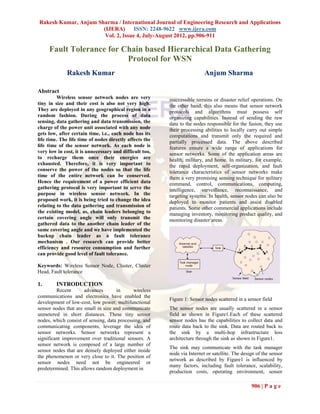
  • 1. Rakesh Kumar, Anjum Sharma / International Journal of Engineering Research and Applications (IJERA) ISSN: 2248-9622 www.ijera.com Vol. 2, Issue 4, July-August 2012, pp.906-911 Fault Tolerance for Chain based Hierarchical Data Gathering Protocol for WSN Rakesh Kumar Anjum Sharma Abstract Wireless sensor network nodes are very inaccessible terrains or disaster relief operations. On tiny in size and their cost is also not very high. the other hand, this also means that sensor network They are deployed in any geographical region in a protocols and algorithms must possess self random fashion. During the process of data organizing capabilities. Instead of sending the raw sensing, data gathering and data transmission, the data to the nodes responsible for the fusion, they use charge of the power unit associated with any node their processing abilities to locally carry out simple gets low, after certain time, i.e., each node has its computations and transmit only the required and life time. The life time of nodes directly affects the partially processed data. The above described life time of the sensor network. As each node is features ensure a wide range of applications for very low in cost, it is unnecessary and difficult too, sensor networks. Some of the application areas are to recharge them once their energies are health, military, and home. In military, for example, exhausted. Therefore, it is very important to the rapid deployment, self-organization, and fault conserve the power of the nodes so that the life tolerance characteristics of sensor networks make time of the entire network can be conserved. them a very promising sensing technique for military Hence the requirement of a power efficient data command, control, communications, computing, gathering protocol is very important to serve the intelligence, surveillance, reconnaissance, and purpose in wireless sensor network. In the targeting systems. In health, sensor nodes can also be proposed work, it is being tried to change the idea deployed to monitor patients and assist disabled relating to the data gathering and transmission of patients. Some other commercial applications include the existing model, as, chain leaders belonging to managing inventory, monitoring product quality, and certain covering angle will only transmit the monitoring disaster areas. gathered data to the another chain leader of the same covering angle and we have implemented the backup chain leader as a fault tolerance mechanism . Our research can provide better efficiency and resource consumption and further can provide good level of fault tolerance. Keywords: Wireless Sensor Node, Cluster, Cluster Head, Fault tolerance 1. INTRODUCTION Recent advances in wireless communications and electronics have enabled the Figure 1: Sensor nodes scattered in a sensor field development of low-cost, low power, multifunctional sensor nodes that are small in size and communicate The sensor nodes are usually scattered in a sensor unmetered in short distances. These tiny sensor field as shown in Figure1.Each of these scattered nodes, which consist of sensing, data processing, and sensor nodes has the capabilities to collect data and communicating components, leverage the idea of route data back to the sink. Data are routed back to sensor networks. Sensor networks represent a the sink by a multi-hop infrastructure less significant improvement over traditional sensors. A architecture through the sink as shown in Figure1. sensor network is composed of a large number of The sink may communicate with the task manager sensor nodes that are densely deployed either inside node via Internet or satellite. The design of the sensor the phenomenon or very close to it. The position of network as described by Figure1 is influenced by sensor nodes need not be engineered or many factors, including fault tolerance, scalability, predetermined. This allows random deployment in production costs, operating environment, sensor 906 | P a g e
  • 2. Rakesh Kumar, Anjum Sharma / International Journal of Engineering Research and Applications (IJERA) ISSN: 2248-9622 www.ijera.com Vol. 2, Issue 4, July-August 2012, pp.906-911 network topology, hardware constraints, transmission protocols utilize position information to relay the data media, and power consumption. to the desired regions rather than the whole network. 2. ROUTING TECHNIQUES IN WSN 3. RELATED WORK Wireless sensor networks (WSN) consist of In general, three strategies are considered small nodes with sensing, computation, and wireless for the design of data aggregation techniques in communications capabilities. Many routing, power WSNs. They are cluster based, tree-based, and chain- management, and data dissemination protocols have based . In this section, we only review three chain- been specifically designed for WSNs where energy based routing protocols, PEGASIS, COSEN, and awareness is an essential design issue. Routing Enhanced PEGASIS, and point out their pros and protocols in WSNs might differ depending on the cons that motivate our research. application and network architecture. Overall, the routing techniques are classified into three categories A. PEGASIS based on the underlying network structure: flat, PEGASIS is a basic chain-based routing hierarchical, and location-based routing. protocol. In which, all nodes in the sensing area are Furthermore, these protocols can be classified into first organized into a chain by using a greedy multipath-based, query-based, negotiation based, QoS-based, and coherent based depending on the algorithm, and then take turns to act as the chain protocol operation. Many routing, power leader. In data dissemination phase, every node receives the sensing information from its closest management, and data dissemination protocols have upstream neighbour, and then passes its aggregated been specifically designed for WSNs where energy data toward the designated leader, via its downstream awareness is an essential design issue. Routing protocols in WSNs might differ depending on the neighbour, and finally the base station. Although the application and network architecture. Overall, the PEGASIS constructs a chain connecting all nodes to balance network energy dissipation, there are still routing techniques are classified into three categories some flaws with this scheme. 1) For a large sensing based on the underlying network structure: flat, field and real-time applications, the single long chain hierarchical, and location-based routing. may introduce an unacceptable data delay time. 2) Furthermore, these protocols can be classified into multipath-based, query-based, and negotiation-based, Since the chain leader is elected by taking turns, for QoS based, and coherent based depending on the some cases, several sensor nodes might reversely transmit their aggregated data to the designated protocol operation. Figure 2 shows routing protocols leader, which is far away from the BS than itself. in WSNs. This will result in redundant transmission paths, and therefore seriously waste network energy. 3) The single chain leader may become a bottleneck. B. COSEN In contrast to PEGASIS, COSEN is a two- tier hierarchical chain-based routing scheme. In that scheme, sensor nodes are geographically grouped into several low-level chains. For each low-level chain, the sensor node with the maximum residual energy is elected as the chain leader. Moreover, with the low-level leaders, a high-level chain and its corresponding chain leader will be eventually formulated. In data communications, all common (normal) nodes perform a similar procedure as that in PEGASIS to send their fused data, via their respective low-level leaders and the high-level leader, toward the BS. COSEN, compared to PEGASIS, Figure 2: Routing Protocols in WSNs although can alleviate the transmission delay and energy consumption, it still introduces a lot of In flat networks all nodes play the same role, while redundant transmission paths, especially for those hierarchical protocols aim to cluster the nodes so that nodes which are nearest to the BS but would detour cluster heads can do some aggregation and reduction their fused data toward the farther leaders. of data in order to save energy. Location-based 907 | P a g e
  • 3. Rakesh Kumar, Anjum Sharma / International Journal of Engineering Research and Applications (IJERA) ISSN: 2248-9622 www.ijera.com Vol. 2, Issue 4, July-August 2012, pp.906-911 C. Enhanced PEGASIS definition of R, different integers (1 … n) are used to indicate distinct angles. In 2007, Jung et al. proposed a variation of PEGASIS routing scheme, termed as Enhanced  Gθ, R : the group id. Theoretically, by PEGASIS. In their method, the sensing area, centered changing different values of θ and R, the at the BS, is circularized into several concentric sensing area can be divided into n * n cluster levels. For each cluster level, based on the groups. Those are G1, 1, G1, 2, …, G1, n, greedy algorithm of PEGASIS, a node chain is …, Gn, 1, …, Gn,, n. constructed. In data transmission, the common nodes also conduct a similar way as the PEGASIS to  ni: the node i; the node set N={n1, n2, n3, transfer their sensing data to its chain leader. After …, ni}, where 1≤i≤|N|. that, from the highest (farthest) cluster level to the  cx,y: the id of a chain which was formed in lowest (near to the BS), a multi-hop and leader-by- group Gx,y. the chain set C={c1,1, c1,2, leader data propagation task will be followed. The ….}. EPEGASIS although has considered the location of the BS to slightly improve the redundant transmission  lx,y: the leader node id of chain cx,y. The path and the network lifetime, there are still some leader set L={l1,1, l1,2, ….}. problems with that scheme. 1) For large sensing  neighbour(ni): the neighbouring nodes of areas, the node chain in each concentric cluster would ni. The neighbouring nodes mean the nodes still become lengthy, and thus result in a longer which are locating in the transmission range transmission delay. 2) Since the leader node election of a specific node. strategy is same as that in PEGASIS (by taking turns), it did not consider the node’s residual energy.  dis(x, y): the distance between nodes x and As a node with the least residual energy is elected to y. The BS can be deemed as a special act as the leader, the network lifetime would be sensor node. significantly affected. 3) While the distribution of B. OPERATION OF CHIRON sensor nodes is not even, the transmission distance between two chain-leaders in different cluster levels The operation of CHIRON protocol consists might be lengthy, this would consume more energy. of four phases: 1) Group Construction Phase. 2) Chain Formation Phase. 3) Leader Node Election 4. CHIRON PROTOCOL Phase. and 4) Data Collection and Transmission Phase. For improving the deficiencies with the aforementioned three schemes, in this section, we 1. Group Construction Phase thus propose an energy efficient hierarchical chain- The main purpose of this phase is ready to divide the based routing protocol, termed as CHIRON. The sensing field into a number of smaller areas so that design philosophy is described as follows. the CHIRON can create multiple shorter chains to A. Network model and assumptions reduce the data propagation delay and redundant transmission path in later phases. Instead of using Without loss of generality, in our research, concentric clusters as EPEGASIS scheme does, the we also consider a WSN of n energy-constrained CHIRON adopts the technique of Beam Star to sensor nodes, which are randomly deployed over a organize its groups. After the sensor nodes are sensing field. The BS is located at a corner of the scattered, the BS gradually sweeps the whole sensing sensing area, and equipped with a directional antenna area, by successively changing different transmission and unlimited power. As a result, the BS can power levels and antenna directions, to send control adaptively adjust its transmission power level and information (including the values of R and θ) to all antenna direction to send control packets to all nodes nodes. After all nodes receiving such control packets, in the WSN. Besides, for easy discussion, we define they can easily determine which group they are some notations as follows: respectively belonging to. In addition, by the received  R: the transmission range of the BS. For signal strength indication (RSSI), every node can also simplicity, we use distinct integers (1 … n) figure out the value of dis(ni, BS). A grouping to represent various ranges. example with R=1...3 and θ=1..2 is shown in Figure 3.  θ: the beam width (covering angle) of the directional antenna. Also, similar to the 908 | P a g e
  • 4. Rakesh Kumar, Anjum Sharma / International Journal of Engineering Research and Applications (IJERA) ISSN: 2248-9622 www.ijera.com Vol. 2, Issue 4, July-August 2012, pp.906-911 Fig. 3 Grouping example with R=1…3 and θ=1...2 2. Chain Formation Phase In this phase, the nodes within each group Gx,y will be linked together to form a chain cx,y, respectively. The chain formation process is same as that in Figure 4: The group chains constructed from Figure 1 PEGASIS scheme. For each group Gx,y, the node ni with the maximum value of dis(ni, BS) (that is farthest away from the BS) is initiated to create the group chain. By using a greedy algorithm, the nearest node (to ni) of neighbor(ni) will be chosen to link the node ni, and become as the newly initiate node in next linking step. The process is repeated until all nodes are put together, and thus finally a group chain cx,y is formed. Figure 2 shows all group chains that are constructed from the sensing environment of Figure 2 3. Leader Node Election Phase For data transmission, a leader node in each group chain must be selected for collecting and forwarding Figure 5: The data transmission flows the aggregated data to the BS. Unlike the PEGASIS and EPEGASIS schemes, in which the leader in each chain is elected in a round-robin manner, CHIRON 4. Data Collection and Transmission Phase chooses the chain leader (lx,y) based on the maximum value Res(ni) of group nodes. Initially, in After completed the previous three phases, the data each group, the node farthest away from the BS is collection and transmission phase begins. The data assigned to be the group chain leader. After that, for transmission procedure in CHIRON is similar to that each data transmission round, the node with the in PEGASIS scheme. Firstly, the normal nodes in maximum residual energy will be elected. The each group Gx,y transmit their collected data along residual power information of each node ni can be the cx,y, by passing through their nearest nodes, to piggybacked with the fused data to the chain leader the chain leader lx,y. And then, starting from the lx,y along the chain cx,y, so that the chain leader can farthest groups, the chain leaders collaboratively determine which node will be the new leader for next relay their aggregated sensing information to the BS, transmission round. in a multi-hop, leader-by-leader transmission manner. In order to avoid a longer transmission distance incurred between two chain leaders, and thus result in a great amount of energy dissipation, 909 | P a g e
  • 5. Rakesh Kumar, Anjum Sharma / International Journal of Engineering Research and Applications (IJERA) ISSN: 2248-9622 www.ijera.com Vol. 2, Issue 4, July-August 2012, pp.906-911 5. IMPROVED CHIRON SCHEMES changes in angles due to the sensing elements . Due to this sensing the time and power. CHIRON is used to split the sensing field into a number of smaller areas, so that it can create multiple shorter chains to reduce the data 4 chiron vs improve x 10 transmission delay and redundant path, and therefore 2 chiron effectively conserve the node energy and prolong the 1.8 improve network lifetime. In CHIRON routing is done on the 1.6 basis of angles. As the routing start from the 1.4 clusterhead to destination the path changes in angles 1.2 due to the sensing elements . Due to this sensing the y(data) time and power dissipation increases hence the 1 CHIRON has not exact output, when we compare to 0.8 the real applications. In proposed schemes 0.6 communication, routing is done between clusterhead 0.4 (CH) to clusterhead (CH) is done directly or as a 0.2 straight line. In proposed scheme network is divide 0 into two parts, so only two sensor element are 0 500 1000 1500 2000 2500 3000 x(time) present between two clusterheads (CHs). Hence we have two straight path for routing. Since the number (a) of sensor elements are reduced so sensing time and power dissipation are reduced hence the 9000 chiron vs improve improvement in CHIRON is possible. chiron 8000 improve 7000 6. SIMULATION AND RESULTS 6000 For evaluation the performance and fault y(balance) 5000 tolerance of our proposed CHIRON protocol, in this 4000 section, we use a simulation tool MATLAB to 3000 conduct several experiments 2000 A. Simulation environment and parameters 1000 In our simulations, we consider three 0 different sizes of sensing area: 100 m*100 m, 200 0 500 1000 1500 2000 2500 3000 x(time) m*200 m, and 300 m*300 m, each is with 100 randomly deployed sensor nodes. The BS is located (b) on the corner of sensing field. Every sensor node is initially equipped with 0.5 joules power. We define the average delay ass the average required hops, and chiron vs improve the redundant transmission path as the number of 15 chiron detour hops, for one node transmits its sensing data to improve the BS, respectively. We also define the simulation round as a duration time in which all sensor nodes sent a 2000-bit packet to the BSS. For each 10 y(distributed) simulation scenario, the results are drawn by the average value of 10 runs. B. Simulation results 5 Figure 6 shows the simulation results of average propagation delay and redundant transmission path for two compared schemes. It could be seen that the proposed scheme. In CHIRON 0 0 500 1000 1500 2000 2500 3000 routing is done on the basis of angles. As the routing x(time) start from the cluster-head to destination the path (c) 910 | P a g e
  • 6. Rakesh Kumar, Anjum Sharma / International Journal of Engineering Research and Applications (IJERA) ISSN: 2248-9622 www.ijera.com Vol. 2, Issue 4, July-August 2012, pp.906-911 Figure 6: Improved results for CHIRON.(a) Graph [3] C. Y. Chong and S. P. Kumar, “Sensor for data on network. (b) Graph for balancing of data Networks: Evolution, Opportunities, and on network. (c) Graph for distribution of data on Challenges,” Proceedings of the IEEE, Vol. network. 91, pp. 1247-1256, 2003. These graph shows the improved result for [4] W. R. Heinzelman, A. Chandrakasan, and H. CHIRON, in which Figure 6.a) shows the data Balakrishnan, “Energy Efficient process on the network even when the energy is get Communication Protocol for Wireless zero. Figure 6.b) shows the balancing of traffic using Microsensor Networks,” Proceedings of the the imroved CHIRON and CHIRON. Improved 33rd Hawaii International Conference on schemes shows the balancing improvement over System Sciences, 2000. CHIRON. Figure 6.c) shows the distributing of traffic [5] W. R. Heinzelman, A. Chandrakasan, and H. using the imroved CHIRON and CHIRON. Balakrishnan, “An Application Specific Improved schemes shows the distributing Protocol Architecture for Wireless improvement over CHIRON. Microsensor Networks,” IEEE Transaction on Wireless Commun. Vol. 1, Issue 4, pp. 660-670, 2002. 7. CONCLUSION [6] E. Altman, T. Basar, T. Jimenez, and N. In this paper, we discuss an efficient Shimkin, “Competitive routing in networks hierarchical chain based routing protocol CHIRON, with polynomial costs,” IEEE Trans. which is suitable for large sensor networks with Automat. Control, vol. 47, no. 1, pp. 92-96, power and time constraints. In our approaches, we 2002. utilize the concept of Beam Star topology to divide the whole sensing field into a number of smaller [7] J. Choi, C. Conrad, C. Malakowsky, J. areas, so that the CHIRON can create multiple Talent, C.S. Yuan, and R.W. Gracy, shorter chains to reduce the data propagation delay “Flavones from Scutellaria baicalensis and redundant transmission path and provide better Georgi attenuate apoptosis and protein fault tolerance, thus significantly save network oxidation in neuronal cell lines,” energy. dissipation increases. Hence the CHIRON Biochemica et Biophysica Acta, 1571: 201- has not exact output when we compare to the real 210 (2002). applications. In proposed schemes communication, routing is done between clusterhead (CH) to clusterhead (CH) is done directly or as a straight line. In proposed scheme network is divide into two parts so only two sensor element are present between two clusterheads (CHs). Hence we have sequential straight path for routing. Since the number of sensor elements are reduced so sensing time and power dissipation are reduced. REFERENCES [1] I. F. Akyildiz, W. Su, Y. Sankarasubramaniam, and E. Cayirci, “A Survey on Sensor Networks,” IEEE Commun. Mag. Vol. 38, pp. 102-114, 2002. [2] J. N. Al-Karaki and A. E. Kamal, “Routing Techniques in Wireless Sensor Networks: A Survey,” Proceedings of the IEEE Wireless Communications, Vol. 11, pp. 6-28, 2004. 911 | P a g e