Transient flow analysis for horizontal axial upper-wind turbine
ToddRamsey313FinalProject
1. Todd Ramsey
5/8/14
MAE 313
Dr. Garrett
T Th 10:30 – 11:45
MAE 313 AIRCRAFT STABILITY PROJECT – 737-300
ABSTRACT
The objective of this project was to evaluate the static stability parameters of the original 737-
300, provided the necessary geometry data of the aircraft. The parameters considered were the
coefficient of moment at zero-degrees angle of attack to check balance, the change in this moment
coefficient with respect to angle of attack, and the stiffness of the aircraft in roll and yaw. After these
values were calculated and the aircraft declared statically stable and balanced, a modification was made
to the aircraft: ten feet were added to the passenger compartment, behind the aerodynamic center. The
new static stability parameters were calculated and compared to those of the original aircraft, with the
new center of gravity location (measured from the nose of the aircraft) being found through the use of
lumped mass models in the x, y and z-directions. The comparison indicated what parameters needed to
be altered in order to achieve the same levels of static stability of the original aircraft. It was
determined that the yaw stiffness needed to be reduced by 0.002, and the coefficient of moment-
variation with angle of attack decreased by 0.0147; this could be accomplished by decreasing the
vertical tail-volume coefficient by 20-percent, by decreasing the vertical tail area by the same amount,
and increasing the dihedral angle from 6 to 12 degrees to combat the reduction in magnitude of the
wing dihedral effect. Since the additional weight pulled the center of gravity back, and assuming no
change (relative to the aerodynamic center) in the neutral point, a mass of approximately 1800 pounds
was removed from the tail section and placed in the nose section. This change is partially justified by
the fact that the weight of the tail structure required will be less, allowing for weight in the tail to be
removed. A dynamic stability analysis was then conducted of the original and modified aircraft, with
the modified aircraft including the changes made to return the new design to the original static stability
levels. It was discovered that the increased weight reduced the natural frequency of the phugoid and
short period modes, while also pulling the lateral mode-poles closer to the origin, coinciding with an
increase in roll and yaw stiffness due to increased moments of inertia. Potential feedback control
systems needed for dynamic stability include the pitot tube, angle of attack vane and yaw damper.
The MATLAB code used to complete this project is included in Appendix A.
I. STATIC STABILITY OF 737-300
Before calculating any of the static stability parameters, a lumped mass model was generated of
the original aircraft in the x (chordwise) and z (vertical) directions. The following assumptions
regarding weight distribution in the cruise/clean configuration were made in the generation of these
models: for the vertical model, 7 percent of the aircraft's weight was below the fuselage (in the
engines), 28 percent to the top of the nacelle and bottom of the fuselage, 27 percent to the fuselage
segment including the wings, 33 percent to the top of the fuselage, and 5 percent to the vertical tail. In
the horizontal direction, the weight distribution was arranged so that 10 percent of the weight was in
the nose, 15 percent in the fuselage up to the front of the nacelles, 25 percent to the segment extending
to the back of the nacelles, 5 percent from this location to the horizontal position of the wing tips, 20
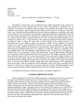
percent to the back of the passenger compartment, and 25 percent to the tail of the aircraft. Fig. (1)
shows these two lumped mass models:
2. Figure 1: Horizontal (left) and vertical (right) lumped mass models, original 737-300.
From these models, an x-center of gravity location of 51 feet (h = 0.6054) from the nose was
obtained, with the model discretized to the nearest foot. Knowing a static margin of 0.18 from the
provided data, a neutral point location of 78.54 percent from the leading edge of the mean aerodynamic
chord was determined, and assumed to be constant through the modifications made to the aircraft.
These models were first used in obtaining the coefficient of moment due to the propulsion
system – two jet engines supplying a combined 5000 pounds of thrust. The moment arm of the
propulsion system about the y-center of gravity (7 feet) was calculated to be 4 feet, resulting in a
coefficient of moment due to propulsion-value of about 0.009, and a zero-degree angle of attack
coefficient of moment-value (CM0) of 0.0222. Being positive, the 737-300 was found to be balanced.
The variation of the coefficient of moment about the aerodynamic center with respect to angle
of attack (Cmα) was calculated simply by multiplying the negative of the provided lift curve slope of the
entire configuration, 0.09, by the static margin, 0.18; a value of -0.162 was obtained. This aircraft is
statically stable in pitch with a negative Cmα.
In the process of calculating the yaw stiffness/vertical fin effectiveness, CNβ, it was assumed that
the fuselage and wing were designed for minimum interference (dσ/dβ = 0), the vertical fin was not in
the slipstream of the air exhausted by the engines, positioned below the wing (VF/V = 1), and the
coefficient of normal force due to the propulsion system did not vary with the sideslip angle (dCNp/dβ =
0). A value of 0.0079 was obtained, indicating a statically stable aircraft in yaw.
In the process of calculating the roll static stability parameter, Clβ, interference from the wing
was assumed to be non-existent, (Clβint = 0), and the lift curve slope of the wing was calculated
(included sweep and mach number-correction) to be -0.0318, indicating a statically stable aircraft in
roll.
II. STATIC STABILITY OF MODIFIED 737-300
The choice was made, for the purpose of examining impact, to add the ten feet to the passenger
compartment behind the aerodynamic center of the wing, resulting in a new length of about 119 feet.
Using the lumped mass models shown in fig. (1), 20 percent of the aircraft's overall weight was
0 2 0 4 0 6 0 8 0 1 0 0 1 2 0
8 0 0
1 0 0 0
1 2 0 0
1 4 0 0
1 6 0 0
1 8 0 0
2 0 0 0
2 2 0 0
2 4 0 0
2 6 0 0
O r ig in a l 7 3 7 H o r iz o n t a l L u m p e d M a s s M o d e l
H o r iz o n t a l P o s it io n ( fe e t , x = 0 a t n o s e )
Lumpedmasses(lbs./ft.)
0 5 1 0 1 5 2 0 2 5 3 0 3 5
0
0 . 2
0 . 4
0 . 6
0 . 8
1
1 . 2
1 . 4
1 . 6
1 . 8
2
x 1 0
4 O rig in a l 7 3 7 V e r t ic a l L u m p e d M a s s M o d e l
V e r t ic a l P o s it io n ( fe e t , x = 0 a t b o t t o m o f fu s e la g e )
Lumpedmasses(lbs./ft.)
3. contained in the rear segment of the passenger compartment, originally 30 feet long. Since one-third of
this density and length is being added the aircraft, one-third of this 20 percent of the original weight
was added to the aircraft, between 84 and 94 feet on the new scale.
New lumped mass models were also generated by the same means with similar weight-
breakdown, and are displayed in fig. (2):
Figure 2: Horizontal (left) and vertical (right) lumped mass models, modified 737-300.
From these models, new x and y-center of gravity locations were determined to be 53 (h =
0.7687) and 7 feet, respectively.
Only one minor alteration was made to CM0: the horizontal tail-volume coefficient was increased
due to the increase in the distance between the aerodynamic centers of the wing and horizontal tail,
resulting in a minor decrease in the value to 0.0220.
Since no change was assumed in the neutral point relative to the wing aerodynamic center, the
new static margin was computed from the new center of gravity location, and multiplied by the
negative of the lift curve slope of the entire configuration (assumed constant, since a relatively small
amount by percentage was added to the body) to obtain the new Cmα of -0.0015.
For the new CNβ, 10 feet also needed to be added to the distance between the aerodynamic
centers of the vertical tail and the wing. This change resulted in a new value of 0.0099.
Since no parameters involved in the determination of Clβ were altered, the value stayed at
-0.0318.
III. RETURNING MODIFIED 737-300 TO ORIGINAL LEVELS OF STATIC STABILITY
In order to return the modified 737 to its original static stability levels, Cmα and Clβ need to be
decreased by 0.0147 and 0.002, respectively. No changes need to be made in the other two parameters.
This might be accomplished by making three changes to the new design. First, reducing the vertical tail
area by twenty percent will effectively reduce the vertical tail-volume coefficient, reducing CNβ by
0.0020, and reducing the tail weight, moving the center of gravity forward. Second, the decrease in the
0 2 0 4 0 6 0 8 0 1 0 0 1 2 0
8 0 0
1 0 0 0
1 2 0 0
1 4 0 0
1 6 0 0
1 8 0 0
2 0 0 0
2 2 0 0
2 4 0 0
2 6 0 0
R e d e s ig n e d 7 3 7 H o r iz o n t a l L u m p e d M a s s M o d e l
H o riz o n t a l P o s it io n ( fe e t , x = 0 a t n o s e )
Lumpedmasses(lbs./ft.)
0 5 1 0 1 5 2 0 2 5 3 0 3 5
0
0 . 5
1
1 . 5
2
2 . 5
x 1 0
4 R e d e s ig n e d 7 3 7 V e r t ic a l L u m p e d M a s s M o d e l
V e rt ic a l P o s it io n ( fe e t , x = 0 a t b o t t o m o f fu s e la g e )
Lumpedmasses(lbs./ft.)
4. magnitude of Clβ that results from the decrease in tail area must be combated by increasing the dihedral
angle from 6 to 12 degrees. Finally, approximately 1800 pounds of structural weight, which would have
otherwise been used to support the larger vertical tail, and placed in the nose to decrease Cmα to it's
original value of -0.162.
Although the relatively rough discretization scheme of examining the aircraft in 1-foot-long
sections results in significant inaccuracies, the above changes were made, and the center of gravity
returned to its original value of 51 feet behind the nose (h = 0.6054), returning the static margin to 0.18.
The 1800 pounds of mass moved from the tail to the nose was determined by computing the
new center of gravity after the weight was removed from the tail (x-cg pushed forward to 52 feet, h =
0.6871), and computing the new Cmα. From this value, a required cg-location was computed with the
change in Cmα that had to be made, and from this, the 1800 pound-value was determined. The removal
of 20 percent of the vertical tail area resulted in a final design weight of 142848 pounds-mass.
IV. DYNAMIC STABILITY OF ORIGINAL 737-300
For the purpose of computing the moments of inertia about the x, y and z-axes, a spanwise (y-
direction) lumped mass model had to be generated, shown in fig. (3) below. For this y-model of the
original design, it was assumed that 5 percent of the weight was on the wing up to the nacelle, 10
percent covering the region of once nacelle, 70 percent over the region including the fuselage, 10
percent on the opposing nacelle section, and 5 percent on the opposing outboard wing section.
Figure 3: Spanwise lumped mass model, original 737-300.
The moments of inertia about each axis were found by 'looping' in MATLAB through the
lumped mass segments, and multiplying these segments by the square of their respective distances from
the center of gravity location. For this portion, it was assumed that vertical component (z-direction) of
0 1 0 2 0 3 0 4 0 5 0 6 0 7 0 8 0 9 0 1 0 0
0
1 0 0 0
2 0 0 0
3 0 0 0
4 0 0 0
5 0 0 0
6 0 0 0
O rig in a l 7 3 7 S p a n w is e L u m p e d M a s s M o d e l
S p a n w is e P o s it io n (fe e t , x = 0 a t b o t t o m o f le ft w in g t ip )
Lumpedmasses(lbs./ft.)
5. these distances was very small, with the only exception being the vertical tail, where the weight is
relatively light. These moments of inertia were then non-dimensionalized by multiplying by eight, and
dividing by the product of the cruise density (12.67e-4 slugs/ft.^3) and the wing reference area. These
values were then divided by the wing span-cubed for the moments of inertia about the x and z-axes, or
the mean aerodynamic chord for the moment of inertia about the y-axis.
The non-dimensional moments of inertia for the original 737-300 were calculated to be 5.389
for ixx, 12012 for iyy, and 31.348 for izz.
Each of the dynamic modes were computed from the mode approximations, which required the
calculation of various other derivatives. The poles of each mode (taking the form of a + b*i, a complex
number) were calculated and plotted from the following formulae:
a=−Dampingconstant∗Nat frequency
(1)
b=Nat frequency∗√(1−Dampingconstant
2
)
(2)
The first of two longitudinal dynamic modes of an aircraft is the phugoid mode – the lightly
damped, low frequency of the aircraft rising and falling in altitude. The second is the short period mode
– the more heavily damped, higher frequency of the aircraft varying it's angle of attack.
The first of three lateral dynamic modes is the spiral mode, or the mode that sees the aircraft
varying in sideslip angle slowly over time. The second is the dutch roll mode, or the simultaneous
variation of the aircraft in yaw and roll. Finally, there is the roll mode.
The calculation of the frequency/damping of the phugoid mode required the calculation of Cxu,
which was simply the coefficient of thrust (equal to the Thrust divided by the dynamic pressure and
reference area) multiplied by negative 2. This assumed no variation in the thrust/drag with mach
number; the divergence mach number much higher than that of cruise, indicating limited
compressibility effects. Using the expressions for phugoid mode-approximations, the natural frequency
and damping constant were found to be 1.7868e-4 rad/s and 0.1613, respectively.
With regard to the other longitudinal dynamic mode, short period, the natural frequency and
damping constant were respectively found to be 0.0012 and 0.1041, respectively. While the natural
frequency of the short period mode is indeed higher than that of the phugoid mode, the damping
constant was unusually found to be less. The poles of these modes, found using eq. (1) and (2), are
shown in fig. (4) below.
6. Figure 4: Longitudinal poles, original 737-300.
While the orders of magnitude for the short period pole appear to be unusually small, the
general form of the longitudinal-poles plot is accurate.
The calculation of the roll pole required knowledge of the Clp derivative, or the variation in lift
with respect to the roll rate. As a function of the lift curve slope of the wing, the taper ratio, and tail-
sizing coefficients, this derivative was calculated to be -0.0232. Dividing this value by the non-
dimensional moment of inertia about the x-axis resulted in the roll eigenvalue, -0.0043.
The spiral mode pole was found by first computing the and Clr derivatives, found respectively
to be -0.0053 and 0.0353. The computation of Cnr required the assumption that very little change in
sideslip angle was seen with respect to yaw. The spiral pole was then evaluated to be an unstable
(positive, right-half-plane) 1.1214e-4.
The dutch roll mode poles, being a function of both roll and yaw stiffness, required the setup of
a coefficient matrix, to be multiplied by the two-element vector of the variation in roll and yaw angles
to obtain the rates of these angles. The eigenvalues were then computed of this matrix using MATLAB,
and taken as the poles of the dutch roll mode. The respective values for 'a' and 'b' were -1e-4 and
-0.0159, indicating a slightly unstable dutch roll mode. These values required knowledge of the Cyr and
Cyβ derivatives, which were found to be 0.0158 and -0.0238, respectively. This calculation also
assumed that ixz = 0, due to the aircraft's symmetry.
Fig. (5) contains the lateral poles of the original 737-300. Again, although the magnitudes for
the poles seem too small (namely the roll pole), the tendencies of the aircraft can still be observed. Both
the dutch roll and spiral modes are marginally unstable, a quality held by many modern commercial
aircraft to reduce drag. The real-component of the roll mode pole is much larger than those of the
spiral/dutch roll modes.
-1 . 5 - 1 - 0 . 5 0
x 1 0
- 4
- 3
- 2
- 1
0
1
2
3
x 1 0
- 3
R e
Im
O r ig in a l 7 3 7 -3 0 0 , L o n g it u d in a l S t a b ilit y
P h u g o id P o le s
S h o r t P e r io d P o le s
7. Figure 5: Lateral poles, original 737-300.
V. DYNAMIC STABILITY OF MODIFIED 737-300
The new moments of inertia for the modified 737-300 were computed to be 5.4327 for ixx,
15758 for iyy, and 39.486 for izz,using the same methods as above.
Fig. (6) contains the spanwise lumped mass model for the modified 737-300, while fig. (7) and
(8) contain the plots of the longitudinal and lateral poles.
Figure 6: Spanwise lumped mass model, modified 737-300.
- 5 - 4 - 3 - 2 -1 0 1
x 1 0
- 3
- 0 . 0 2
- 0 . 0 1 5
- 0 . 0 1
- 0 . 0 0 5
0
0 . 0 0 5
0 . 0 1
0 . 0 1 5
0 . 0 2
R e
Im
O r ig in a l 7 3 7 - 3 0 0 , L a t e ra l S t a b ilit y
R o ll p o le
D u t c h r o le p o le s
S p ira l p o le
0 1 0 2 0 3 0 4 0 5 0 6 0 7 0 8 0 9 0 1 0 0
0
1 0 0 0
2 0 0 0
3 0 0 0
4 0 0 0
5 0 0 0
6 0 0 0
M o d ifie d 7 3 7 S p a n w is e L u m p e d M a s s M o d e l
S p a n w is e P o s it io n ( fe e t , x = 0 a t b o t t o m o f le ft w in g t ip )
Lumpedmasses(lbs./ft.)
8. Figure 7: Longitudinal poles, modified 737-300.
Figure 8: Lateral poles, modified 737-300.
Comparison of fig. (4) and (7) reveals that the phugoid poles have shifted closer to the real axis,
indicating a decrease in natural frequency, provided the damping has remained constant. The natural
frequency decreased as a result of the modification to 1.6887e-4. This is expected, as an increase in
overall weight/mass fraction should decrease the natural frequency. The natural frequency of the short
-1 . 5 - 1 - 0 . 5 0
x 1 0
- 4
- 3
- 2
- 1
0
1
2
3
x 1 0
- 3
R e
Im
M o d ifie d 7 3 7 - 3 0 0 , L o n g it u d in a l S t a b ilit y
P h u g o id P o le s
S h o r t P e r io d P o le s
- 5 - 4 - 3 - 2 -1 0 1
x 1 0
- 3
- 0 . 0 2
- 0 . 0 1 5
- 0 . 0 1
- 0 . 0 0 5
0
0 . 0 0 5
0 . 0 1
0 . 0 1 5
0 . 0 2
R e
Im
M o d ifie d 7 3 7 - 3 0 0 , L a t e ra l S t a b ilit y
R o ll p o le
D u t c h r o le p o le s
S p ir a l p o le
9. period mode also decreased to 0.001, with a slight increase in the damping constant to 0.1129.
Comparison of Fig. (5) and (8) show the spiral pole moving closer to the origin/left-half-plane,
indicating a slight increase in stability. As the mass of the aircraft increases, the resistance to yaw
would be greater. This is indeed the case, as the spiral pole moved from 1.1214e-4 to 1.3726e-5. The
roll pole, on the other hand, moved in the opposite direction, from -0.0043 to -0.0039, and closer to
instability. The dutch roll pole imaginary-components decreased from 0.0159 to 0.0142. All poles were
pulled closer to the origin, indicating an increase in the aircraft's stiffness in yaw and roll due to the
increases in the moments of inertia.
VI. RETURNING THE MODIFIED 737-300 TO ORIGINAL DYNAMIC STABILITY
Seeing as the increased weight/moments of inertia about the y and z-axes pulled all of the poles
closer to the origin, feedback control systems must be implemented to improve and maintain stability.
With regard to the phugoid mode, which is close to the right-half-plane and thus closer to instability, a
speed controller could be introduced, governed by an autopilot, with the pitot tube measuring airspeed
acting as the sensor. This could also be supplemented by an altimeter, to hold a constant altitude and
suppress the phugoid mode. The short period mode could be held in check with the placement of an
angle of attack vane on the outside of the aircraft, which measures the orientation of the aircraft in the
inertial frame (using a gyro) while also taking into account the angle of the incoming air (this sensor
also being 'read' by the autopilot). Since this is a large-scale passenger aircraft, suppressing the short
period is perhaps the most important of the modes to suppress. As the dutch roll mode is also close to
instability, a yaw damper could also be used, which takes the sideslip angle-input and adjusts the rudder
deflection to counter the plane's tendency to perform this maneuver.
APPENDIX A
%% Todd Ramsey - 5/1/14 - MAE 313 Final Project - Dr. Garrett
% Original aircraft data:
S_ref = 1135; % ft.^2.
b = 94.75; % feet.
a = 0.09; % Lift curve slope, per degree (entire configuration).
a_t = 0.09; % Per degree.
a_vt = 0.09; % Per degree.
AR = 8.99;
Taper = 0.24;
c_mean_aero = 12.25; % feet.
e = 0.7; % Oswald efficiency coefficient.
CL_0wing = 0.12;
Sweep = 25*pi/180; % Radians.
Dihedral = 6*pi/180; % Radians.
eps0 = 0.02*pi/180; % Zero-angle of attack Downwash, Radians.
d_eps_d_alpha = 0.08; % Per degree.
CM_0_wb = 0.015;
i_t = -1*pi/180; % Radians.
SM = 0.18; % Static Margin.
d_sigma_d_alpha = 0.1; % Sidewash, per degree.
d_sigma_d_phat = 0;
z_F = 45; % feet.
W_original = 135000; % Pounds.
V_hbar = 1.35;
10. V_vbar = 0.1;
S_v = 300; % ft.^2.
S_h = 208; % ft.^2.
Length_original = 109.583; % feet.
Height_original = 34.5; % feet.
% Cruising Conditions:
Altitude = 20000; % feet.
V = 300*1.678; % ft./s.
Density = 12.67*10^-4; % slugs/ft.^3.
Dyn_pressure = 0.5*Density*V^2;
Thrust = 5000;
%% CALCULATING THE STATIC STABILITY PARAMETERS OF ORIGINAL DESIGN: (737-300)
% Constructing a lumped-mass model, for the purpose of estimating the
% chord-wise location of the center of gravity:
% Horizontal model:
x = 1:1:109;
Lump_weight_horizontal_original = zeros(109,1);
for i = 1:1:length(x)
if i <= 13 % To edge of nose.
Lump_weight_horizontal_original(i) = W_original*(1/13)*0.1;
elseif i <= 36 % To front edge of nacelle.
Lump_weight_horizontal_original(i) = W_original*(1/(36-13)*0.15);
elseif i <= 50 % To back of nacelle.
Lump_weight_horizontal_original(i) = W_original*(1/(50-36)*0.25);
elseif i <= 54 % To trailing edge of wing.
Lump_weight_horizontal_original(i) = W_original*(1/(54-50)*0.05);
elseif i <= 84 % To edge of passenger compartment.
Lump_weight_horizontal_original(i) = W_original*(1/(84-54)*0.2);
else % To tail of a/c.
Lump_weight_horizontal_original(i) = W_original*(1/(109-84)*0.25);
end
end
figure(1);
plot(x,Lump_weight_horizontal_original,'k'); grid on;
title('Original 737 Horizontal Lumped Mass Model');
xlabel('Horizontal Position (feet, x=0 at nose)'); ylabel('Lumped masses
(lbs./ft.)');
% Vertical model:
y = 1:1:34;
Lump_weight_vertical_original = zeros(34,1);
for i = 1:1:length(y)
if i <= 2 % To bottom of fuselage.
Lump_weight_vertical_original(i) = W_original*(1/(2)*0.07);
elseif i <= 5 % To top of nacelle.
Lump_weight_vertical_original(i) = W_original*(1/(5-2)*0.28);
elseif i <= 7 % to wing tips.
Lump_weight_vertical_original(i) = W_original*(1/(7-5)*0.27);
elseif i <= 13 % To top of fuselage.
Lump_weight_vertical_original(i) = W_original*(1/(13-7)*0.33);
else % To top of vertical tail.
Lump_weight_vertical_original(i) = W_original*(1/(34-13)*0.05);
end
end
11. figure(2);
plot(y,Lump_weight_vertical_original,'k'); grid on;
title('Original 737 Vertical Lumped Mass Model');
xlabel('Vertical Position (feet, x=0 at bottom of fuselage)'); ylabel('Lumped
masses (lbs./ft.)');
% Calculating the x and y locations of the center of gravity:
% (From x = 0 at nose, y = 0 at bottom of nacelles)
weight_sum = 0; % initialize counter.
for i = 1:1:109
weight_sum = weight_sum + Lump_weight_horizontal_original(i);
if weight_sum >= 135000/2
x_original_cg = i;
break;
end
end
weight_sum = 0;
for i = 1:1:34
weight_sum = weight_sum + Lump_weight_vertical_original(i);
if weight_sum >= 135000/2
y_original_cg = i;
break;
end
end
% Calculating h, given distance from root leading edge:
Tip_chord = 5;
Root_chord = Tip_chord/Taper;
Leading_edgex = 35 + (Root_chord - c_mean_aero);
h_original = (x_original_cg - Leading_edgex)/c_mean_aero;
h_n = h_original + SM;
% Stability parameters: --------------------------------------------
% CM_0:
Thrust_moment_arm = 4; % Distance from y-point cg to center of nacelles.
CM_0_P = (Thrust * (Thrust_moment_arm))/(Dyn_pressure*S_ref*c_mean_aero);
CM_0_original = CM_0_wb + CM_0_P + a_t*V_hbar*(eps0 + i_t)*(1-
(a_t/a)*(S_h/S_ref)*(1 - d_eps_d_alpha));
% CM_alpha:
CM_alpha_original = a*(-SM);
% CN_beta:
V_F_over_V = 1; % Vertical Fin not in jet slipstream.
d_sigma_d_beta = 0; % Assuming limited impact from fuse, wing.
l_f_bar = V_vbar*S_ref*b/S_v;
l_f = l_f_bar - (x_original_cg - (Leading_edgex + 0.25*c_mean_aero));
V_v = l_f*S_v/(S_ref*b);
d_Cnp_d_beta = 0; % Assumping no change in propulsion force with sideslip.
CN_beta_original = V_v*a_vt*(V_F_over_V)^2*(1-d_sigma_d_beta) + d_Cnp_d_beta;
% Cl_beta:
% Calculating of wing lift-curve slope:
a_w = (pi/180)*(2*pi*cos(Sweep))/((1 - 0.8^2*cos(Sweep)^2 + (2*pi*cos(Sweep)/
12. (pi*AR))^2)^(1/2) + (2*pi*cos(Sweep)/(pi*AR)));
CL_beta_int = 0; % Little interference from wing.
Cl_beta_original = -(a_w/4)*(2*(1+2*Taper))/(3*(1+Taper))*Dihedral - (1+2*Taper)/
(6*(1+Taper))*(CL_0wing)*sin(2*Sweep) - S_v*z_F/(S_ref*b)*a_vt*(1-
d_sigma_d_beta)*(V_F_over_V)^2 + CL_beta_int;
%% CALCULATING THE STATIC STABILITY PARAMETERS OF NEW DESIGN:
% Adding 10 feet to the passenger compartment (behind wing):
W_new = W_original + (1/3)*0.2*W_original;
% Constructing an updated lumped-mass model, for the purpose of estimating
% the chord-wise location of the center of gravity:
% Horizontal model:
x_new = 1:1:119;
Lump_weight_horizontal_new = zeros(119,1);
for i = 1:1:length(x_new)
if i <= 13 % To edge of nose.
Lump_weight_horizontal_new(i) = W_new*(1/13)*0.095;
elseif i <= 36 % To front edge of nacelle.
Lump_weight_horizontal_new(i) = W_new*(1/(36-13)*0.14);
elseif i <= 50 % To back of nacelle.
Lump_weight_horizontal_new(i) = W_new*(1/(50-36)*0.235);
elseif i <= 54 % To trailing edge of wing.
Lump_weight_horizontal_new(i) = W_new*(1/(54-50)*0.045);
elseif i <= 94 % To edge of passenger compartment.
Lump_weight_horizontal_new(i) = W_new*(1/(94-54)*0.25);
else % To tail of a/c.
Lump_weight_horizontal_new(i) = W_new*(1/(119-94)*0.235);
end
end
figure(3);
plot(x_new,Lump_weight_horizontal_new,'k'); grid on;
title('Redesigned 737 Horizontal Lumped Mass Model');
xlabel('Horizontal Position (feet, x=0 at nose)'); ylabel('Lumped masses
(lbs./ft.)');
y = 1:1:34;
Lump_weight_vertical_new = zeros(34,1);
for i = 1:1:length(y)
if i <= 2 % To bottom of fuselage.
Lump_weight_vertical_new(i) = W_new*(1/(2)*0.05);
elseif i <= 5 % To top of nacelle.
Lump_weight_vertical_new(i) = W_new*(1/(5-2)*0.28);
elseif i <= 7 % to wing tips.
Lump_weight_vertical_new(i) = W_new*(1/(7-5)*0.29);
elseif i <= 13 % To top of fuselage.
Lump_weight_vertical_new(i) = W_new*(1/(13-7)*0.34);
else % To top of vertical tail.
Lump_weight_vertical_new(i) = W_new*(1/(34-13)*0.04);
end
end
figure(4);
plot(y,Lump_weight_vertical_new,'k'); grid on;
title('Redesigned 737 Vertical Lumped Mass Model');
xlabel('Vertical Position (feet, x=0 at bottom of fuselage)'); ylabel('Lumped
masses (lbs./ft.)');
13. % Calculating the x and y locations of the new center of gravity:
% (From x = 0 at nose, y = 0 at bottom of nacelles)
weight_sum = 0; % initialize counter.
for i = 1:1:119
weight_sum = weight_sum + Lump_weight_horizontal_new(i);
if weight_sum >= 144000/2
x_new_cg = i;
break;
end
end
weight_sum = 0;
for i = 1:1:34
weight_sum = weight_sum + Lump_weight_vertical_new(i);
if weight_sum >= 144000/2
y_new_cg = i;
break;
end
end
% Calculating h, given distance from root leading edge:
Leading_edgex = 35 + (Root_chord - c_mean_aero);
h_new = (x_new_cg - Leading_edgex)/c_mean_aero;
% CM_0:
l_t_bar_original = V_hbar*c_mean_aero*S_ref/S_h; % Assuming negligible change in
neutral point location.
l_t_bar_new = l_t_bar_original + 10;
V_hbar_new = V_hbar*(l_t_bar_new/l_t_bar_original);
CM_0_new = CM_0_wb + CM_0_P + a_t*V_hbar_new*(eps0 + i_t)*(1-(a_t/a)*(S_h/S_ref)*(1
- d_eps_d_alpha));
% CM_alpha:
CM_alpha_new = -a*(h_n - h_new);
% CN_beta:
l_f_bar_new = l_f_bar + 10;
l_f_new = l_f_bar_new - (x_new_cg - (Leading_edgex + 0.25*c_mean_aero));
V_v_new = l_f_new*S_v/(S_ref*b);
d_Cnp_d_beta = 0;
CN_beta_new = V_v_new*a_vt*(V_F_over_V)^2*(1-d_sigma_d_beta) + d_Cnp_d_beta;
% Cl_beta: (no change)
Cl_beta_new = -(a_w/4)*(2*(1+2*Taper))/(3*(1+Taper))*Dihedral - (1+2*Taper)/
(6*(1+Taper))*(CL_0wing)*sin(2*Sweep) - S_v*z_F/(S_ref*b)*a_vt*(1-
d_sigma_d_beta)*(V_F_over_V)^2 + CL_beta_int;
%% REDESIGNING THE AIRCRAFT TO ACQUIRE ORIGINAL STATIC STABILITY LEVELS:
% CN_beta needs to decrease by 0.002;
% CM_alpha needs to decrease by 0.0147;
% Potential solution: Decrease tail volume coefficient by 20 percent
% by decreasing vertical tail area by the same amount, and increasing the
% dihedral angle to combat the increase in Cl_beta. Cm_alpha will have
% become more negative by the center of gravity having been pulled forward
14. % by the reduction in tail weight. CM_0 remains unchanged.
% CN_beta:
S_v_refined = 0.8*S_v;
V_v_refined = l_f_new*S_v_refined/(S_ref*b);
CN_beta_refined = V_v_refined*a_vt*(V_F_over_V)^2*(1-d_sigma_d_beta) +
d_Cnp_d_beta;
% Cl_beta:
Dihedral_refined = Dihedral*2; % Dihedral angle has been doubled.
Cl_beta_refined = -(a_w/4)*(2*(1+2*Taper))/(3*(1+Taper))*Dihedral_refined -
(1+2*Taper)/(6*(1+Taper))*(CL_0wing)*sin(2*Sweep) - S_v_refined*z_F/
(S_ref*b)*a_vt*(1-d_sigma_d_beta)*(V_F_over_V)^2 + CL_beta_int;
% CM_alpha:
% New horizontal center of gravity location must be computed from change in
% tail weight:
W_r = W_new - (0.04*0.2*W_new);
Lump_weight_horizontal_r = zeros(119,1);
for i = 1:1:length(x_new)
if i <= 13 % To edge of nose.
Lump_weight_horizontal_r(i) = W_r*(1/13)*0.1;
elseif i <= 36 % To front edge of nacelle.
Lump_weight_horizontal_r(i) = W_r*(1/(36-13)*0.14);
elseif i <= 50 % To back of nacelle.
Lump_weight_horizontal_r(i) = W_r*(1/(50-36)*0.24);
elseif i <= 54 % To trailing edge of wing.
Lump_weight_horizontal_r(i) = W_r*(1/(54-50)*0.05);
elseif i <= 94 % To edge of passenger compartment.
Lump_weight_horizontal_r(i) = W_r*(1/(94-54)*0.25);
else % To tail of a/c.
Lump_weight_horizontal_r(i) = W_r*(1/(119-94)*0.22);
end
end
% x-location of cg:
weight_sum = 0; % initialize counter.
for i = 1:1:119
weight_sum = weight_sum + Lump_weight_horizontal_r(i);
if weight_sum >= W_r/2
x_r_cg = i;
break;
end
end
% New h:
h_r = (x_r_cg - Leading_edgex)/c_mean_aero;
CM_alpha_r = -a*(h_n - h_r);
% CM_alpha still needs to decrease by 0.0073:
% Required decrease in h: (forward cg movement)
change_dif = 0.0162/a;
15. h_required = h_n - change_dif;
change_h = -(h_r - h_required);
% CG must move forward by 1 foot:
% Solution: Take 1420 (1 percent total weight) pounds of weight off of the
% tail and place it in the nose section: (This can be done due to a smaller
% structural requirement, due to the reduction in vertical tail weight).
Lump_weight_horizontal_r2 = zeros(119,1);
for i = 1:1:length(x_new)
if i <= 13 % To edge of nose.
Lump_weight_horizontal_r2(i) = W_r*(1/13)*0.11;
elseif i <= 36 % To front edge of nacelle.
Lump_weight_horizontal_r2(i) = W_r*(1/(36-13)*0.14);
elseif i <= 50 % To back of nacelle.
Lump_weight_horizontal_r2(i) = W_r*(1/(50-36)*0.24);
elseif i <= 54 % To trailing edge of wing.
Lump_weight_horizontal_r2(i) = W_r*(1/(54-50)*0.05);
elseif i <= 94 % To edge of passenger compartment.
Lump_weight_horizontal_r2(i) = W_r*(1/(94-54)*0.25);
else % To tail of a/c.
Lump_weight_horizontal_r2(i) = W_r*(1/(119-94)*0.21);
end
end
% x-location of cg:
weight_sum = 0; % initialize counter.
for i = 1:1:119
weight_sum = weight_sum + Lump_weight_horizontal_r2(i);
if weight_sum >= W_r/2
x_r2_cg = i;
break;
end
end
% New h:
h_r2 = (x_r2_cg - Leading_edgex)/c_mean_aero;
CM_alpha_refined = -a*(h_n - h_r2);
%% CALCULATING DYNAMIC STABILITY PARAMETERS OF ORIGINAL 737-300: -----
CL_0 = CL_0wing - a_t*(S_h/S_ref)*(i_t + eps0);
Mass = W_original/32.2; % In slugs.
Mu = 2*Mass/(Density*S_ref*c_mean_aero);
% Lumped mass model in y-direction:
Lump_weight_y_original = zeros(95,1);
for i = 1:1:95
if i < 26 % To horizontal tail tip.
Lump_weight_y_original(i) = W_original*(1/27*0.05);
elseif i < 39 % Covers first nacelle.
Lump_weight_y_original(i) = W_original*(1/(40-27)*0.10);
elseif i < 57 % Covers fuselage.
Lump_weight_y_original(i) = W_original*(1/(58-40)*0.70);
elseif i < 70 % Covers second nacelle.
Lump_weight_y_original(i) = W_original*(1/(71-58)*0.10);
else % Covers final wing portion.
Lump_weight_y_original(i) = W_original*(1/(95-71)*0.05);
16. end
end
figure(5);
plot(1:1:95,Lump_weight_y_original,'k'); grid on;
title('Original 737 Spanwise Lumped Mass Model');
xlabel('Spanwise Position (feet, x=0 at bottom of left wingtip)'); ylabel('Lumped
masses (lbs./ft.)');
% PHUGOID MODE APPROXIMATIONS:
% CX_u: (Jet)
C_T = Thrust/(Dyn_pressure*S_ref);
% Assuming No variation in thrust/drag w/ Mach number (limited
% compressibility effects):
CX_u_original = -2*C_T;
Damp_Phugoid_original = -CX_u_original/(2*CL_0*sqrt(2));
Nat_Phugoid_original = CL_0/(Mu*sqrt(2));
% Poles:
a_Phugoid_original = -Damp_Phugoid_original*Nat_Phugoid_original;
b_Phugoid_original = Nat_Phugoid_original*sqrt(1 - Damp_Phugoid_original^2);
% SHORT PERIOD MODE APPROXIMATIONS:
% Moment of inertia about y-axis:
% i_yy = 8*I_yy/(Rhow*S*c^3);
I_yy_original = 0;
for i = 1:1:109
I_yy_original = I_yy_original +
Lump_weight_horizontal_original(i)/32.2*abs(x_original_cg - x(i))^2;
end
i_yy_original = 8*I_yy_original/(Density*S_ref*c_mean_aero^3);
% CZ_alpha:
CZ_alpha = -a;
% CM_q:
Tail_efficiency = 1; % T-tail; minimal change in effective dyn. pressure.
l_t = (l_t_bar_original - (x_original_cg - (Leading_edgex + 0.25*c_mean_aero)));
V_h = l_t*S_h/(c_mean_aero*S_ref);
CM_q_original = -2.2*a_t*V_h*(l_t/(c_mean_aero*Tail_efficiency));
Damp_SP_original = -(i_yy_original*CZ_alpha + 2*Mu*CM_q_original)/
(2*sqrt(2*Mu*i_yy_original*(CZ_alpha*CM_q_original - 2*Mu*CM_alpha_original)));
Nat_SP_original = sqrt((CZ_alpha*CM_q_original - 2*Mu*CM_alpha_original)/
(2*Mu*i_yy_original));
a_SP_original = -Damp_SP_original*Nat_SP_original;
b_SP_original = Nat_SP_original*sqrt(1 - Damp_SP_original^2);
% Plotting original, longitudinal poles:
figure(6);
plot([a_Phugoid_original a_Phugoid_original],[b_Phugoid_original
-b_Phugoid_original],'ok',[a_SP_original a_SP_original],[b_SP_original
-b_SP_original],'or');
grid on; legend('Phugoid Poles','Short Period Poles'); axis([-1.5e-4 0 -0.003
0.003]);
17. xlabel('Re'); ylabel('Im'); title('Original 737-300, Longitudinal Stability');
% ROLL MODE APPROXIMATIONS:
Cl_p_original = -(a_w/12)*((1+3*Taper)/(1+Taper)) - 2*(S_v/S_ref)*(z_F/b)^2*a_vt;
% Calculating moment of inertia about x axis:
% i_xx = 8*I_xx/(Rhow*S*b^3);
Spanwisey = 1:1:95;
Spanwise_cg = 48;
I_xx_original = 0;
for i = 1:1:95
I_xx_original = I_xx_original + Lump_weight_y_original(i)/32.2*abs(Spanwise_cg
- Spanwisey(i))^2;
end
i_xx_original = 8*I_xx_original/(Density*S_ref*b^3);
Roll_pole = (Cl_p_original/i_xx_original);
% SPIRAL MODE APPROXIMATIONS:
% I_zz estimation:
I_zz_original = 0;
for i = 1:1:109
if i <= 95
I_zz_original = I_zz_original +
Lump_weight_y_original(i)/32.2*abs(Spanwise_cg - Spanwisey(i))^2 +
Lump_weight_horizontal_original(i)/32.2*abs(x_original_cg - x(i))^2;
else
I_zz_original = I_zz_original +
Lump_weight_horizontal_original(i)/32.2*abs(x_original_cg - x(i))^2;
end
end
i_zz_original = 8*I_zz_original/(Density*S_ref*b^3);
% CN_r_original:
% ASSUMING SMALL CHANGE IN SIDESLIP WITH RESPECT TO YAW.
CN_r_original = -a_vt*V_v*(2*(l_f/b));
% CL_r_original:
CL_r_original = CL_0/6*((1+3*Taper)/(1+Taper)) + a_vt*(S_v*z_F/
(S_ref*b))*(2*(l_f/b));
% Spiral Pole:
Spiral_pole = (CN_r_original -
(CN_beta_original*CL_r_original)/Cl_beta_original)/i_zz_original;
% DUTCH ROLL MODE APPROXIMATIONS:
% CY_r:
CY_r_original = a_vt*(S_v/S_ref)*(2*(l_f/b));
% CY_beta:
CY_beta_original = -a_vt*(S_v/S_ref);
18. DM1 = CY_beta_original/(2*Mu);
DM2 = CY_r_original/(2*Mu) - 1;
DM3 = i_xx_original*CN_beta_original/(i_xx_original*i_zz_original);
DM4 = i_xx_original*CN_r_original/(i_xx_original*i_zz_original);
Dutch_matrix = [DM1 DM2; DM3 DM4];
% ASSUMING I_xz = 0; (symmetry)
% Dutch Roll Pole:
Eigen_Dutch_original = eigs(Dutch_matrix);
a_Dutch_original = -0.0001;
b_Dutch_original = -0.0159;
% Plotting original, lateral poles:
figure(7);
plot(Roll_pole,0,'ok',[a_Dutch_original a_Dutch_original],[-b_Dutch_original
b_Dutch_original],'or',Spiral_pole,0,'ob');
xlabel('Re'); ylabel('Im'); grid on;
title('Original 737-300, Lateral Stability');
legend('Roll pole','Dutch role poles','Spiral pole');
axis([-5e-3 1e-3 -0.02 0.02]);
%% CALCULATING DYNAMIC STABILITY PARAMETERS FOR MODIFIED 737-300:
CL_0 = CL_0wing - a_t*(S_h/S_ref)*(i_t + eps0);
Mass = W_r/32.2; % In slugs.
Mu = 2*Mass/(Density*S_ref*c_mean_aero);
% Lumped mass model in y-direction:
Lump_weight_y_new = zeros(95,1);
for i = 1:1:95
if i < 26 % To horizontal tail tip.
Lump_weight_y_new(i) = W_original*(1/27*0.05);
elseif i < 39 % Covers first nacelle.
Lump_weight_y_new(i) = W_original*(1/(40-27)*0.10);
elseif i < 57 % Covers fuselage.
Lump_weight_y_new(i) = W_original*(1/(58-40)*0.7581);
elseif i < 70 % Covers second nacelle.
Lump_weight_y_new(i) = W_original*(1/(71-58)*0.10);
else % Covers final wing portion.
Lump_weight_y_new(i) = W_original*(1/(95-71)*0.05);
end
end
figure(8);
plot(1:1:95,Lump_weight_y_new,'k'); grid on;
title('Modified 737 Spanwise Lumped Mass Model');
xlabel('Spanwise Position (feet, x=0 at bottom of left wingtip)'); ylabel('Lumped
masses (lbs./ft.)');
% PHUGOID MODE APPROXIMATIONS:
% CX_u: (Jet)
C_T = Thrust/(Dyn_pressure*S_ref);
% Assuming No variation in thrust/drag w/ Mach number (limited
% compressibility effects):
CX_u_new = -2*C_T;
19. Damp_Phugoid_new = -CX_u_new/(2*CL_0*sqrt(2));
Nat_Phugoid_new = CL_0/(Mu*sqrt(2));
% Poles:
a_Phugoid_new = -Damp_Phugoid_new*Nat_Phugoid_new;
b_Phugoid_new = Nat_Phugoid_new*sqrt(1 - Damp_Phugoid_new^2);
% SHORT PERIOD MODE APPROXIMATIONS:
% Moment of inertia about y-axis:
I_yy_new = 0;
for i = 1:1:119
I_yy_new = I_yy_new + Lump_weight_horizontal_r2(i)/32.2*abs(x_original_cg -
x_new(i))^2;
end
i_yy_new = 8*I_yy_new/(Density*S_ref*c_mean_aero^3);
% CZ_alpha:
CZ_alpha = -a;
% CM_q:
Tail_efficiency = 1; % T-tail; minimal change in effective dyn. pressure.
l_t_new = l_t + 10;
V_h = l_t_new*S_h/(c_mean_aero*S_ref);
CM_q_new = -2.2*a_t*V_h*(l_t_new/(c_mean_aero*Tail_efficiency));
Damp_SP_new = -(i_yy_new*CZ_alpha + 2*Mu*CM_q_new)/
(2*sqrt(2*Mu*i_yy_new*(CZ_alpha*CM_q_new - 2*Mu*CM_alpha_refined)));
Nat_SP_new = sqrt((CZ_alpha*CM_q_new - 2*Mu*CM_alpha_refined)/(2*Mu*i_yy_new));
a_SP_new = -Damp_SP_new*Nat_SP_new;
b_SP_new = Nat_SP_new*sqrt(1 - Damp_SP_new^2);
% Plotting new, longitudinal poles:
figure(9);
plot([a_Phugoid_new a_Phugoid_new],[b_Phugoid_new -b_Phugoid_new],'ok',[a_SP_new
a_SP_new],[b_SP_new -b_SP_new],'or');
grid on; legend('Phugoid Poles','Short Period Poles'); axis([-1.5e-4 0 -0.003
0.003]);
xlabel('Re'); ylabel('Im'); title('Modified 737-300, Longitudinal Stability');
% ROLL MODE APPROXIMATIONS:
Cl_p_new = -(a_w/12)*((1+3*Taper)/(1+Taper)) -
2*(S_v_refined/S_ref)*(z_F/b)^2*a_vt;
% Calculating moment of inertia about x axis:
% i_xx = 8*I_xx/(Rhow*S*b^3);
Spanwisey = 1:1:95;
Spanwise_cg = 48;
I_xx_new = 0;
for i = 1:1:95
I_xx_new = I_xx_new + Lump_weight_y_new(i)/32.2*abs(Spanwise_cg -
Spanwisey(i))^2;
end
i_xx_new = 8*I_xx_new/(Density*S_ref*b^3);