Python Notes for mca i year students osmania university.docx
Capacitors
1. Capacitors
Why Are Capacitors Important?
What Is A Capacitor?
Voltage Current Relationships In Capacitors
Energy In Capacitors
What Is Impedance?
Using Impedance
Some Impedance Laws/Combinations
Why Are Capacitors Important?
The capacitor is a widely used electrical component. It has several features
that make it useful and important:
A capacitor can store energy, so capacitors are often found in power
supplies.
A capacitor has a voltage that is proportional to the charge (the integral of
the current) that is stored in the capacitor, so a capacitor can be used to
perform interesting computations in op-amp circuits, for example.
Circuits with capacitors exhibit frequency-dependent behavior so that
circuits that amplify certain frequencies selectively can be built.
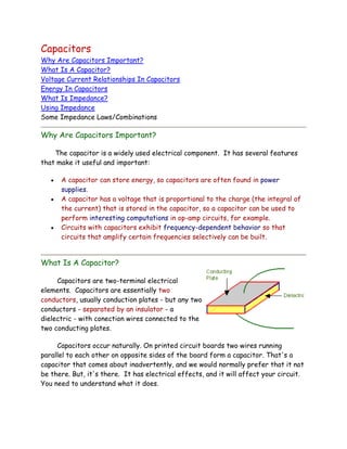
What Is A Capacitor?
Capacitors are two-terminal electrical
elements. Capacitors are essentially two
conductors, usually conduction plates - but any two
conductors - separated by an insulator - a
dielectric - with conection wires connected to the
two conducting plates.
Capacitors occur naturally. On printed circuit boards two wires running
parallel to each other on opposite sides of the board form a capacitor. That's a
capacitor that comes about inadvertently, and we would normally prefer that it not
be there. But, it's there. It has electrical effects, and it will affect your circuit.
You need to understand what it does.
2. At other times, you specifically want to use capacitors because of their
frequency dependent behavior. There are lots of situations where we want to
design for some specific frequency dependent behavior. Maybe you want to filter
out some high frequency noise from a lower frequency signal. Maybe you want to
filter out power supply frequencies in a signal running near a 60 Hz line. You're
almost certainly going to use a circuit with a capacitor.
Sometimes you can use a capacitor to store energy. In a subway car, an
insulator at a track switch may cut off power from the car for a few feet along
the line. You might use a large capacitor to store energy to drive the subway car
through the insulator in the power feed.
Capacitors are used for all these purposes, and more. In this chapter you're
going to start learning about this important electrical component. Remember
capacitors do the following and more.
Store energy
Change their behavior with frequency
Come about naturally in circuits and can change a circuit's behavior
Goals
You need to know what you should get from this lesson on capacitors. Here's
the story.
Given a capacitor,
o Be able to write and use the voltage-current relationship for the
capacitor,
o Be able to compute the current through a capacitor when you know
the voltage across a capacitor.
Given a capacitor that is charged,
o Be able to compute the amount of energy that is stored in the
capacitor.
Capacitors and inductors are both elements that can store energy in purely
electrical forms. These two elements were both invented early in electrical history.
The capacitor appeared first as the legendary Leyden jar, a device that consisted
of a glass jar with metal foil on the inside and outside of the jar, kind of like the
3. picture below. This schematic/picture shows a battery attached to leads on the
Leyden jar capacitor.
Although this device first appeared in
Leyden, a city in the Netherlands sometime
before 1750. It was discovered by E. G. von
Kleist and Pieter van Musschenbroek. Although it
has been around for about 250 years, it has all
of the elements of a modern capacitor, including:
Two conducting plates. That's the metallic foil in the Leyden jar.
An insulator that separates the plates so that they make no electrical
contact. That's the glass jar - the Leyden jar.
The way the Leyden jar operated was that
charge could be put onto both foil elements. If
positive charge was put onto the inside foil, and
negative charge on the outside foil, then the two
charges would tend to hold each other in place.
Modern capacitors are no different and usually
consist of two metallic or conducting plates that
are arranged in a way that permits charge to be bound to the two plates of the
capacitor. A simple physical situation is the one shown at the right.
If the top plate contains positive charge, and the bottom plate contains
negative charge, then there is a tendency for the charge to be bound on the
capacitor plates since the positive charge attracts the negative charge (and
thereby keeps the negative charge from flowing out of the capacitor) and in turn,
the negative charge tends to hold the positive charge in place. Once charge gets on
the plates of a capacitor, it will tend to stay there, never moving unless there is a
conductive path that it can take to flow from one plate to the other.
There is also a standard circuit symbol for a capacitor. The figure below shows a
sketch of a physical capacitor, the corresponding circuit symbol, and the
relationship between Q and V. Notice how the symbol for a capacitor captures the
essence of the two plates and the insulating dielectric between the plates.
4. Now, consider a capacitor that starts out with no charge on either plate. If
the capacitor is connected to a circuit, then the same charge will flow into one
plate as flows out from the other. The net result will be that the same amount of
charge, but of opposite sign, will be on each plate of the capacitor. That is the
usual situation, and we usually assume that if an amount of charge, Q, is on the
positive plate then -Q is the amount of charge on the negative plate.
The essence of a capacitor is that it stores charge. Because they store
charge they have the properties mentioned earlier - they store energy and they
have frequency dependent behavior. When we examine charge storage in a
capacitor we can understand other aspects of the behavior of capacitors.
In a capacitor charge can accumulate on the two plates. Normally charge of
opposite polarity accumulates on the two plates, positive on one plate and negative
on the other. It is possible for that charge to stay there. The positive charge on
one plate attracts and holds the negative charge on the other plate. In that
situation the charge can stay there for a long time.
That's it for this section. You now know pretty much what a capacitor is.
What you need to learn yet is how the capacitor is used in a circuit - what it does
when you use it. That's the topic of the next section. If you can learn that then
you can begin to learn some of the things that you can do with a capacitor.
Capacitors are a very interesting kind of component. Capacitors are one large
reason why electrical engineers have to learn calculus, especially about derivatives.
In the next section you'll learn how capacitors influence voltage and current.
Voltage-Current Relationships In Capacitors
There is a relationship between the charge on a capacitor and the voltage
across the capacitor. The relationship is simple. For most dielectric/insulating
materials, charge and voltage are linearly related.
5. Q=CV
where:
V is the voltage across the plates.
You will need to define a polarity for that voltage. We've defined the
voltage above. You could reverse the "+" and "-".
Q is the charge on the plate with the "+" on the voltage polarity definition.
C is a constant - the capacitance of the capacitor.
The relationship between the charge on a capacitor and the voltage across
the capacitor is linear with a constant, C, called the capacitance.
Q=CV
When V is measured in volts, and Q is measured in couloumbs, then C has the
units of farads. Farads are really coulombs/volt.
The relationship, Q = C V, is the most important thing you can know about
capacitance. There are other details you may need to know at times, like how the
capacitance is constructed, but the way a capacitor behaves electrically is
determined from this one basic
relationship.
Shown to the right is a circuit
that has a voltage source, Vs, a
resistor, R, and a capacitor, C. If you
want to know how this circuit works,
you'll need to apply KCL and KVL to
the circuit, and you'll need to know
how voltage and current are related
in the capacitor. We have a
relationship between voltage and
charge, and we need to work with it to get a voltage current relationship. We'll
look at that in some detail in the next section.
The basic relationship in a capacitor is that the voltage is proportional to the
charge on the "+" plate. However, we need to know how current and voltage are
6. related. To derive that relationship you need to realize that the current flowing
into the capacitor is the rate of charge flow into the capacitor. Here's the
situation. We'll start with a capacitor with a time-varying voltage, v(t), defined
across the capacitor, and a time-varying current, i(t), flowing into the capacitor.
The current, i(t), flows into the "+" terminal taking the "+" terminal using the
voltage polarity definition. Using this definition we have:
ic(t) = C dvc(t)/dt
This relationship is the fundamental relationship between current and voltage
in a capacitor. It is not a simple proportional relationship like we found for a
resistor. The derivative of voltage that appears in the expression for current
means that we have to deal with calculus and differential equations here - whether
we want to or not.
Question
Q1 If the voltage across a capacitor is descreasing (and voltage and current are
defined as above) is the current positive of negative?
This derivative kind of relationship also has some implications for what
happens in a capacitor, and we are going to spend some time exploring that
relationship. Clearly, we need to understand what this relationship implies, and then
we need to learn how it affects things when we write circuit equations using KVL
and KCL.
We'll start by considering a time varying
voltage across a capacitor. To have something
specific, let's say that we have a 4.7 f capacitor,
and that the voltage across the capacitor is the
voltage time function shown below. That voltage
rises from zero to ten volts in one millisecond, then
stays constant at ten volts. Before you go on try to
determine what the current through the capacitor
looks like, then answer these questions.
7. Questions
Q2. Is the current constant in the time interval from t = 0 to t = 10 msec?
Q3. Is the current constant in the time interval from t = 10 msec to the last time
shown?
If current is proportional to the time derivative of voltage, there is only one
time segment, from t = 0 to 1 millisecond, where the voltage derivative is
non-zero, so that's the only time there is any currrent that is non-zero.
After one millisecond has elapsed, the voltage derivative goes to zero, so
there isn't any current then. If there isn't any current, then the voltage
stays constant because no charge is flowing in or out. Remember, current is
charge flow!
The voltage derivative is constant from t = 0 to 1 millisecond. If that's true,
then the current is constant in that period.
Now, you should be able to compute the current.
Energy In Capacitors
Storing energy is very important. You count on the energy stored in your gas
tank if you drove a car to school or work today. That's an obvious case of energy
storage. There are lots of other places where energy is stored. Many of them are
not as obvious as the gas tank in a car. Here are a few.
You're reading this on a computer, and the computer keeps track of the date
and time. It does that by keeping a small part of the computer running when
you think that the computer is turned off. There's a small battery that
stores the energy to keep the clock running when everything else is turned
off.
If you own a stereo or television that you have to plug into the wall plug,
then you should realize that the wall plug voltage becomes zero 120 times a
second. When that happens, the system keeps running because there are
8. capacitors inside the system that store energy to carry you through those
periods when the line voltage isn't large enough to keep things going!
Capacitors can't really be used to store a lot of energy, but there are many
situations in which a capacitor's ability to store energy becomes important. In this
lesson we will discuss how much energy a capacitor can store.
Capacitors are often used to store energy.
When relatively small amounts of energy are needed.
Where batteries are not desired because they might deteriorate.
For larger power/short duration applications - as in power supply filters, or
to keep power up long enough for a computer to shut down gracefully when
the line power fails.
To calculate how much energy is stored in a capacitor, we start by looking at
the basic relationship between voltage and current in a capacitor.
i(t) = C dv(t)/dt
Once we have this relationship, we can calculate the power - the
rate of flow of energy into the capacitor - by multiplying the current
flowing through the capacitor by the voltage across the capacitor.
P(t) = i(t)v(t)
Given the expression for the power:
P(t) = i(t)v(t)
And given the expression for the current:
i(t) = C dv(t)/dt
We can use the expression for current in the power expression:
P(t) = (C dv(t)/dt) v(t)
We can recognize that power is simply rate of energy input.
P(t) = dE/dt = (C dv(t)/dt) v(t)
9. Now, the derivative of energy can be integrated to find the total energy
input.
P(t) = dE/dt = (C dv(t)/dt) v(t)
gives
Now, assuming that the initial voltage is zero (there is no energy stored in
the capacitor initially, we find that the energy stored in a capacitor is
proportional to the capacitance and to the square of the voltage across the
capacitor.
Ec = (1/2)CV2
The expression for the energy stored in a capacitor resembles other energy
storage formulae.
For kinetic energy, with a mass, M, and a velocity, v.
EM = (1/2)MV2
For potential energy, with a spring constant, K, and an elongation, x.
ESpring = (1/2)Kx2
Since the square of the voltage appears in the energy formula, the energy
stored is always positive. You can't have a negative amount of energy in the
capacitor. That means you can put energy into the capacitor, and you can
take it out, but you can't take out more than you put in.
Power in to the capacitor can be negative. Voltage can be positive while
current is negative. Imagine a capacitor that is charged. You could charge a
capacitor by putting a battery across the capacitor, for example. Then, if
you placed a resistor across the capacitor, charge would leave the capacitor
- current would flow out of the capacitor - and the energy in the capacitor
10. would leave the capacitor only to become heat energy in the
resistor. When energy leaves the capacitor, power is negative.
When you use capacitors in a circuit and you analyze the circuit
you need to be careful about sign conventions. Here are the
conventions we used, and these conventions were assumed in any
results we got in this lesson.
Frequency Dependent Behavior For A Capacitor
We start with a capacitor with a sinusoidal voltage across it.
where:
vC(t) = Voltage across the capacitor
iC(t) = Current through the capacitor
C = Capacitance (in farads)
We will assume that the voltage across the capacitor is sinusoidal:
vC(t) = Vmax sin( t)
Knowing the voltage across the capacitor allows us to calculate the current:
iC(t) = C dvC(t)/dt = C Vmax cos( t) = Imax cos( t)
where Imax = C Vmax
Comparing the expressions for the voltage and current we note the following.
The voltage and the current are both sinusoidal signals (a sine function or a
cosine function) at the same frequency.
The current leads the voltage. In other words, the peak of the current
occurs earlier in time than the peak of the voltage signal.
The current leads the voltage by exactly 90o. It will always be exactly 90o
in a capacitor.
The magnitude of the current and the magnitude of the voltage are related:
Vmax/Imax = 1/ C
11. Now, with these observations in hand, it is possible to see that there may be
an algebraic way to express all of these facts and relationships. The method
reduces to the following.
If we have a circuit with sinusoidally varying voltages and currents (as we
would have in a circuit with resistors, capacitors and inductors and sinusoidal
voltage and current sources) we associate a complex variable with every
voltage and current in the circuit.
The complex variable for a voltage or current encodes the amplitude and
phase for that voltage or current.
The voltage and current variables can be used (using complex algebra) to
predict circuit behavior just as though the circuit were a resistive circuit.
We need to do two things here. First, we can illustrate what we mean with an
example. Secondly, we need to justify the claim above. We will look at an example
first, and we will do two examples. The first example is jsut the capacitor - all by
itself. The second example will be one that you have considered earlier, a simple
RC low-pass filter.
Example 1 - The Capacitor
In a capacitor with sinusoidal voltage and currents, we have:
where:
vC(t) = Voltage across the inductor
vC(t) = Vmax sin( t)
iC(t) = Current through the inductor
iC(t) = C Vmax cos( t) = Imax cos( t)
C = Capacitance (in farads)
We represent the voltage with a complex variable, V. Considering this as a
complex variable, it has a magnitude of Vmaxand and angle of 0o. We would write:
V = Vmax/0o
Similarly, we can get a representation for the current. However, first note:
iC(t) = C Vmax cos( t) = Imax cos( t) = Imax sin( t + 90o)
12. (Here you must excuse the mixing of radians and degrees in the argument of the
sine. The only excuse is that everyone does it!) Anyhow, we have:
I = Imax/90o = j Imax = j C Vmax
Where j is the square root of -1.
Then we would write:
V/I = Vmax/j C Vmax = 1/j C
and the quantity 1/j C is called the impedance of the capacitor. In the next
section we will apply that concept to a small circuit - one you should have seen
before.
Before moving to the next section, a little reflection is in order. Here are
some points to think about.
A phasor summarizes information about a sinusoidal signal. Magnitude and
phase information are encoded into the phasor. Frequency information is not
encoded, and there is a tacit assumption that all signals are of the same
frequency, which would be the case in a linear circuit with sinusoidal voltage
and current sources.
We looked at a case where we encoded a signal Vmax sin( t) into a phasor of
Vmax/0o. That was completely arbitrary, and many others would have
encoded Vmax cos( t) into a phasor of Vmax/0o.
Phasors are intended only to show relative phase information, and it doesn't
matter which way you go.
Using Impedance
In the last section we began to talk about the concept of impedance. Let us
do that a little more formally. We begin by defining terms.
A sinusoidally varying signal (vC(t) = Vmax sin( t) for example) will be
represented by a phasor, V, that incorporates the magnitude and phase angle of
the signal as a magnitude and angle in a complex number. Examples include these
taken from the last section. (Note that these phasors have nothing to do with any
TV program about outer space.)
vC(t) = Vmax sin( t)
13. is represented by a phasor V = Vmax/0o
iC(t) = Imax sin( t + 90o)
is represented by a phasor I = Imax/90o
va(t) = VA sin( t + )
is represented by a phasor Va = VA/
Next, we can use the relationships for voltage and current phasors to analyze
a circuit. Here is the circuit.
Now, this circuit is really a frequency
dependent voltage divider, and it is analyzed
differently in another lesson. However,
here we will use phasors. At the end of this
analysis, you should compare how difficult it
is using phasors to the method in the other
lesson.
We start by noting that the current in
the circuit - and there is only one current -
has a phasor representation:
I = Imax/0o
We will use the current phase as a reference, and measure all other phases from
the current's phase. That's an arbitrary decision, but that's the way we will start.
Next we note that we can compute the voltage across the capacitor.
VC = I/j C
This expression relates the current phasor to the phasor that represents the
voltage across the capacitor. The quantity 1/j C is the impedance of the
capacitor. In the last section we justified this relationship.
We can also compute the phasor for the voltage across the resistor.
VR = IR
14. This looks amazingly like Ohm's law, and it is, in fact, Ohm's law, but it is in phasor
form. For that matter, the relationship between voltage and current phasors in a
capacitor - just above - may be considered a generalized form of Ohm's law!
Now, we can also apply Kirchhoff's Voltage Law (KVL) to compute the phasor
for the input voltage.
VIN = VR + VC = IR + I/j C = I(R + 1/j C)
You should note the similarities in what happens here and what happens when
you have two resistors in series.
If you have a resistor, R, and a capacitor, C, in series, the current phasor
can be computed by dividing the input voltage phasor by the sum of R and
1/j C.
If you have two resistors in series (call them R1and R2), the current can be
computed by dividing the input voltage by the sum of R1and R2.
Example
Consider a series circuit of a resistor and capacitor. The series impedance is:
Z = R + 1/j C
That's the same as we showed just above. The impedance can be used to predict
relationships between voltage and current. Assume that the voltage across the
series connection is given by:
vSeries(t) = Vmax cos( t)
That corresponds to having a voltage phasor of:
V = Vmax/0o
We also know that the impedance establishes a relationship between the voltage
and current phasors in the series circuit. In particular, the voltage phasor is the
product of the current phasor and the impedance.
V=IZ
15. For our particular impedance, we have:
V = I*(R + 1/j C)
So, we can solve for the current phasor:
I = V / (R + 1/j C)
Now, we know the voltage phasor and we know the impedance so we can compute
the current phasor. Let us look at some particular values.
Assume:
R = 1.0 k
C = .1 f = 10-7 f
f = 1 kHz, so = 2 103
Vmax = 20 v
Then:
ZR = 1.0 k
ZC = 1/(j C) = 1/(j2 103 10-7 ) = j 1.59 k
And, the total impedance is:
Z = ZR + ZC = (1.0 + j 1.59) k
This impedance value can also be expressed in polar notation:
Z = 1.878 /62o
Now, compute the current phasor:
I = V / (R + 1/j C)
Substituting values, we find:
I = V / Z = Vmax/0o / 1.878 /62o =20/0o / 1.878 /62o
I = V / Z = (20 / 1.878) /-62o = 10.65 /-62oamps
16. And, we need to examine exactly what this means for the current as a function of
time. But that isn't very difficult. We can write out the expression for the
current from what we have above.
iC(t) = 10.65 cos( t - 62o) amps