This document provides an overview of UML class diagrams, including their purpose and essential elements. A UML class diagram visually describes the structure of a system by showing classes, attributes, operations, and relationships. Key elements include classes, associations, generalization, dependencies, and notes. The document also provides examples and tips for creating UML class diagrams.
In this document
Powered by AI
Introduction to UML Class Diagrams, discussing definition and agenda for the presentation.
Description of class diagrams, covering system structure, classes, attributes, operations, and relationships.
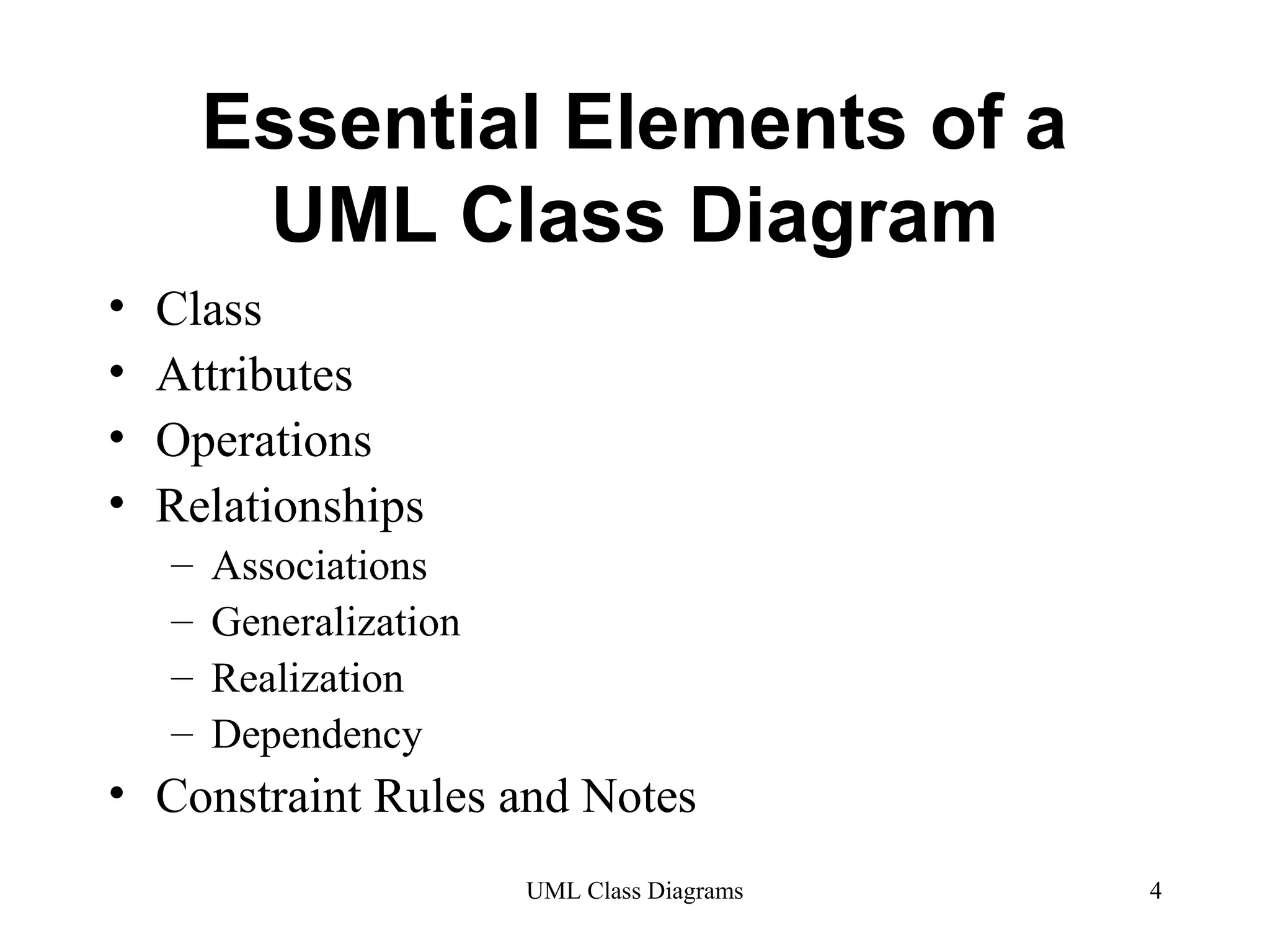
Essential elements comprise class, attributes, operations, relationships including associations, generalization, realization, dependency, and constraints.
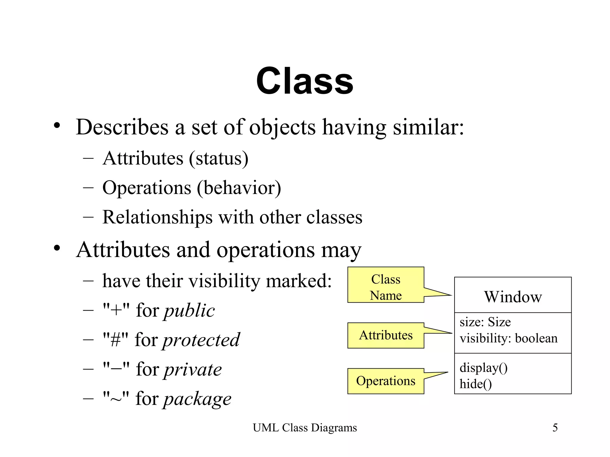
Details on classes including attributes, operations, and their visibility (public, protected, private).
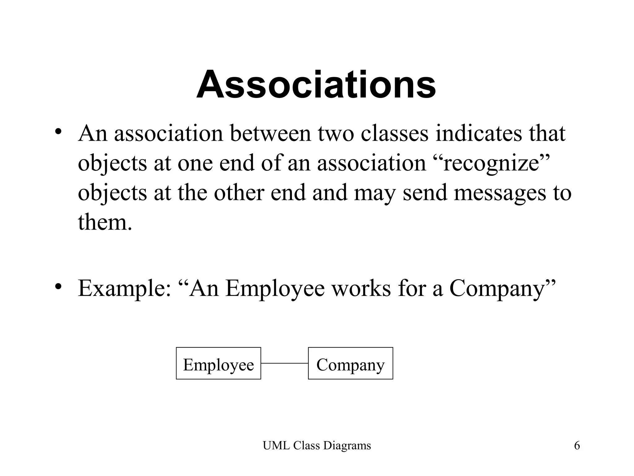
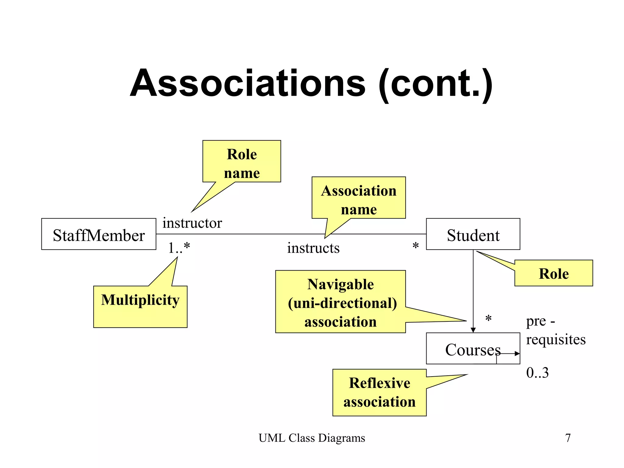
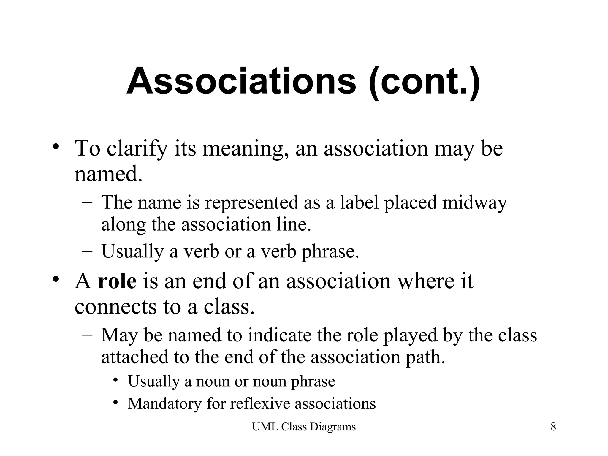
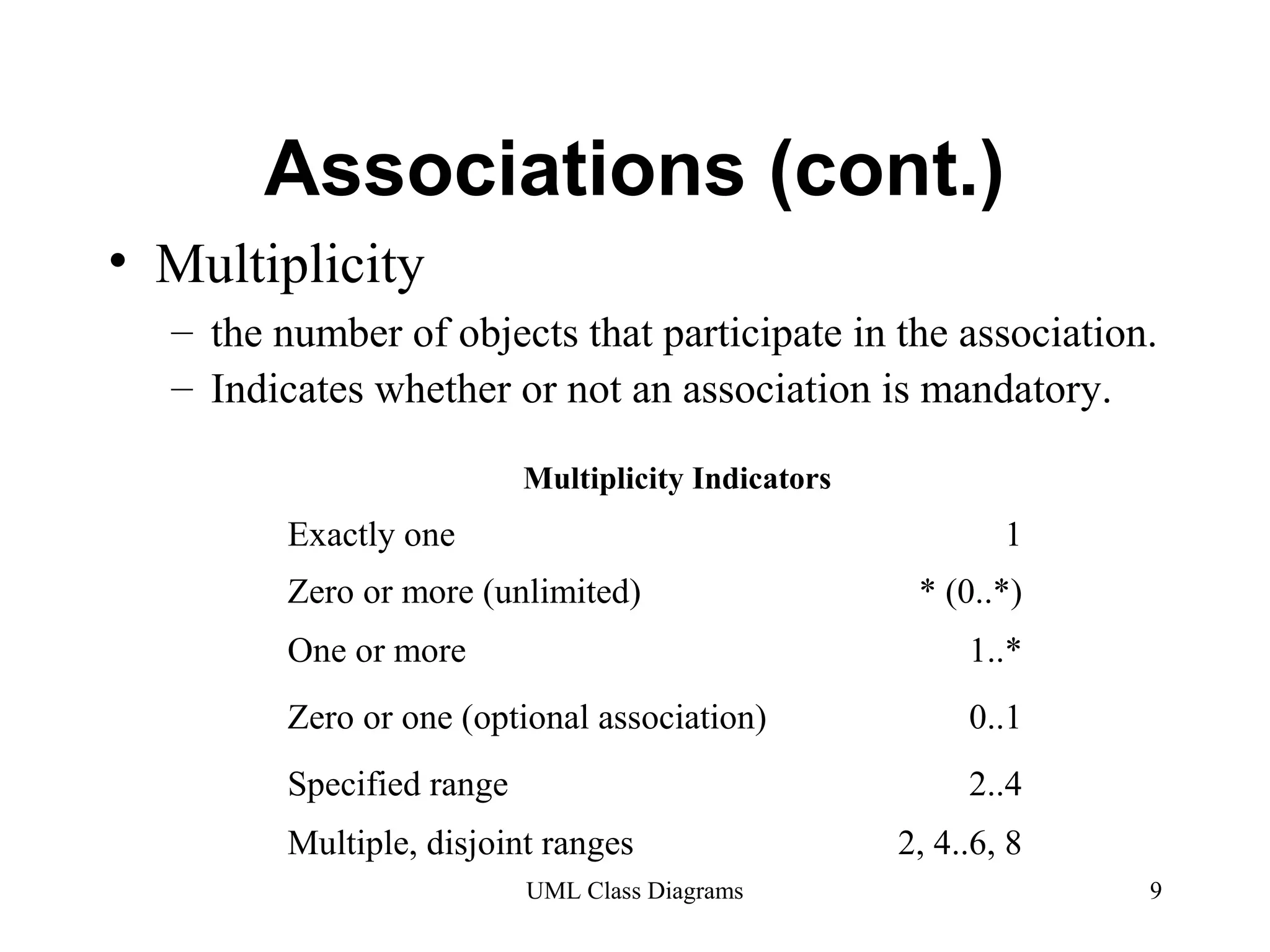
Detailed exploration of associations between classes, navigation, naming conventions, multiplicity indicators.
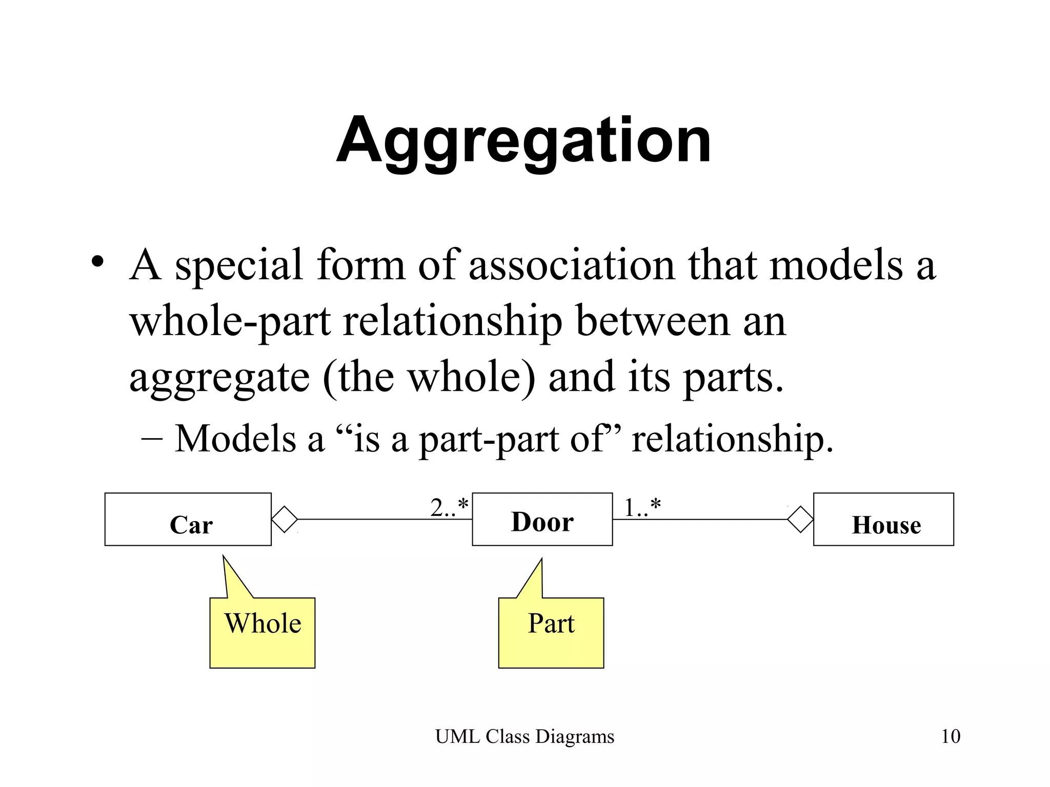
Aggregation as a whole-part relationship, criteria to define aggregation including intrinsic asymmetry.
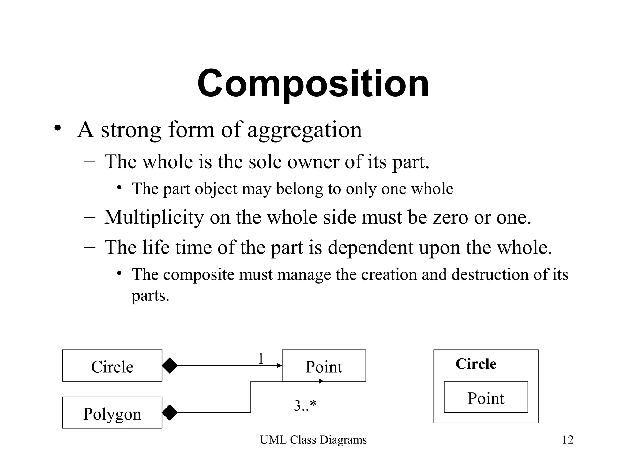
Composition as a strong form of aggregation, detailing ownership, life cycle, and multiplicity.
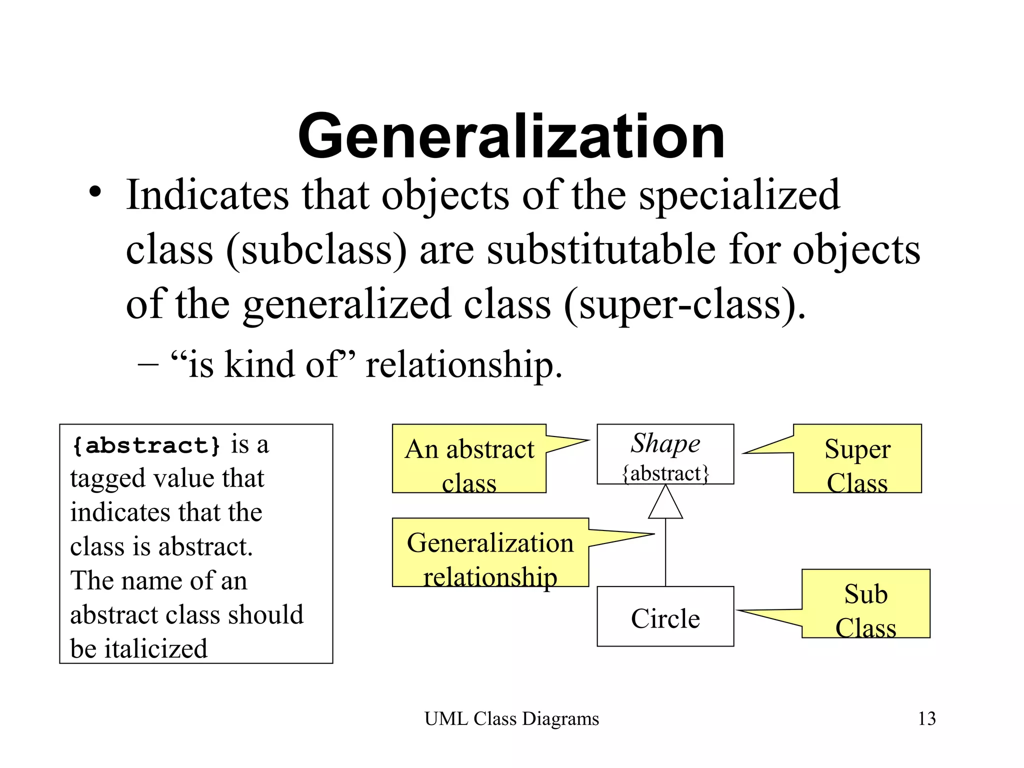
Explanation of generalization indicating subclass and superclass relationships, inheritance of attributes and operations.
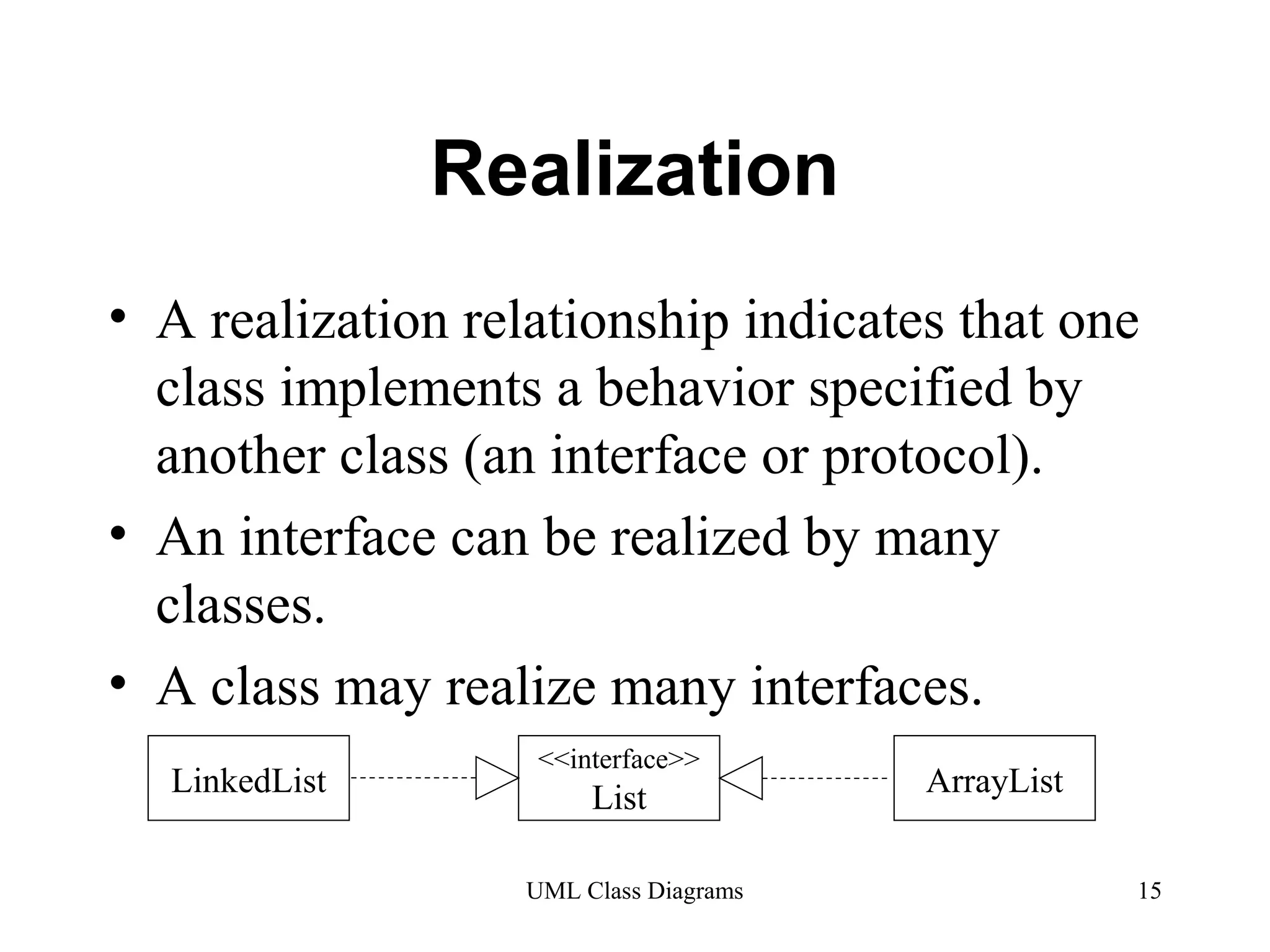
Definition of realization relationships, class implementations of interfaces and protocols.
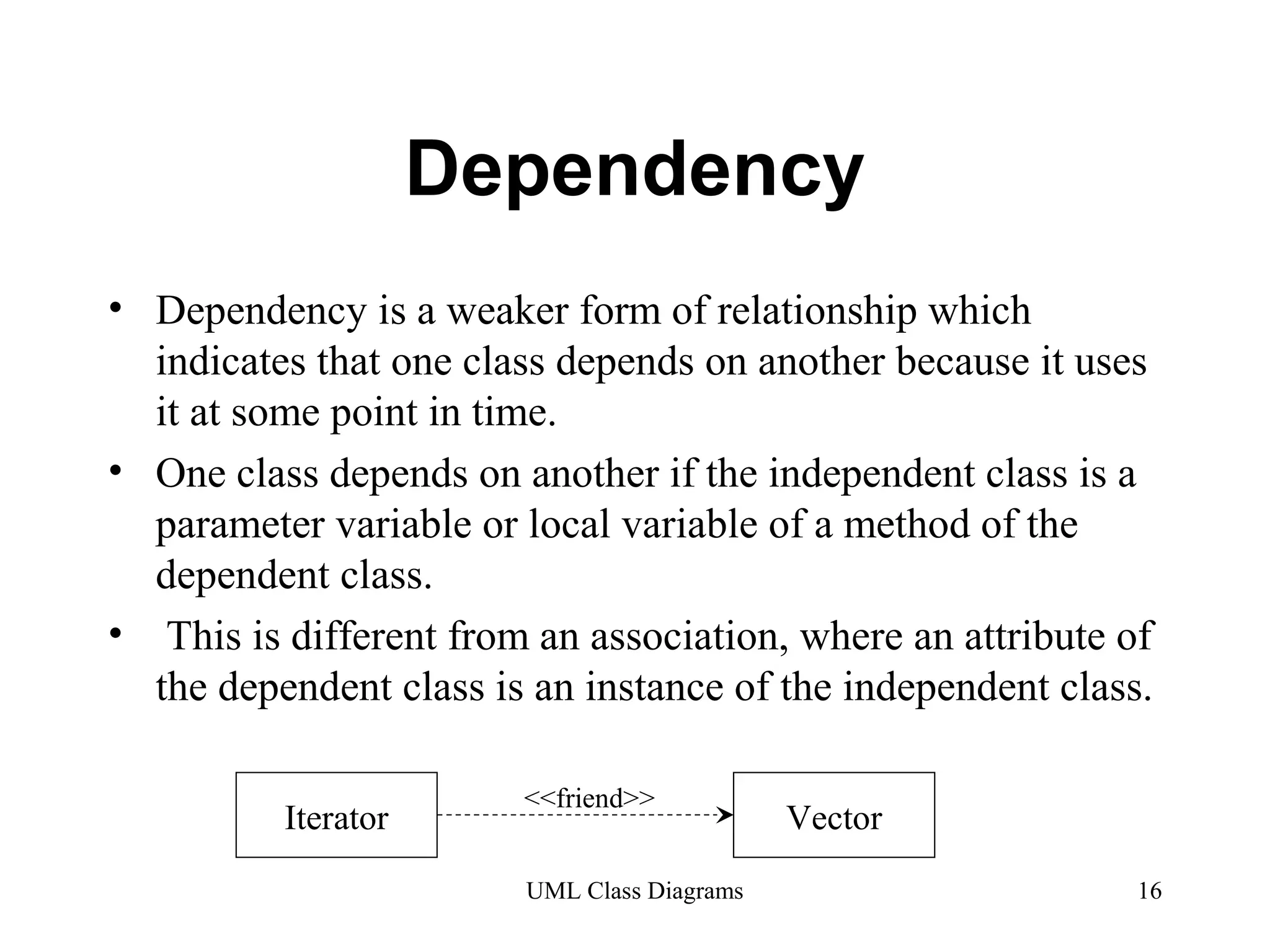
Overview of dependency as a weaker relationship indicating class usage at various instances.
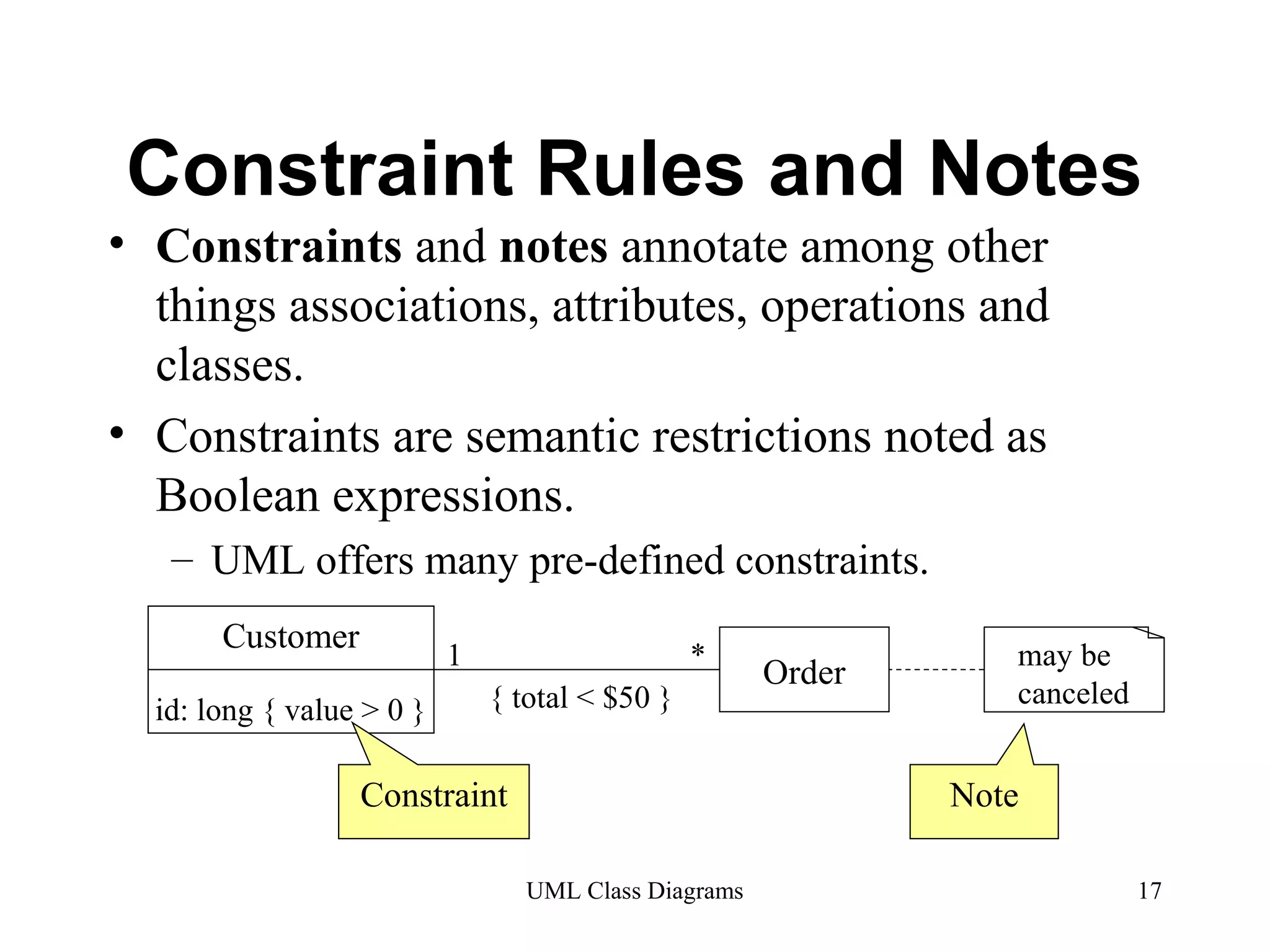
Discusses constraints and notes used in UML class diagrams, detailing semantic restrictions.
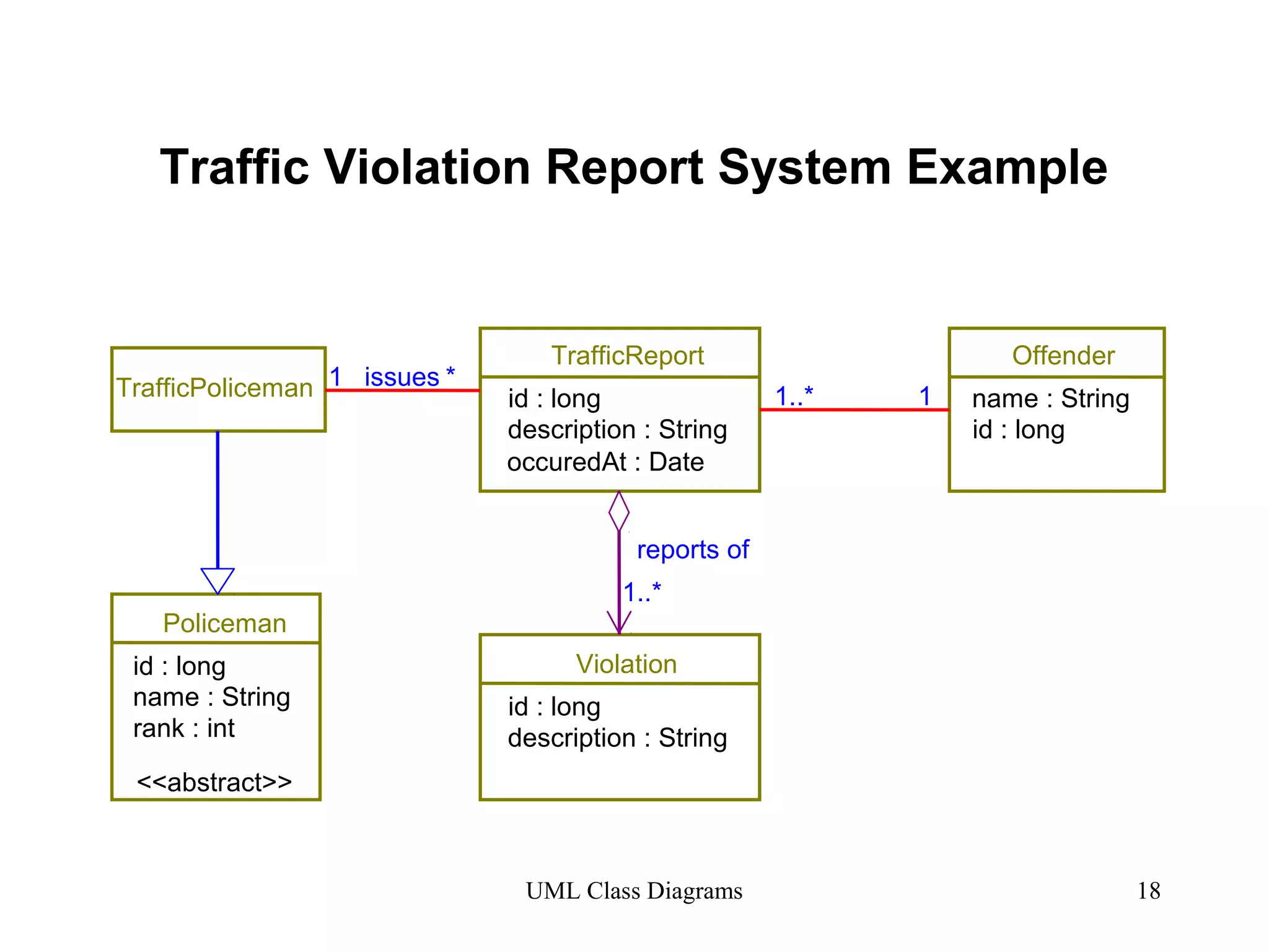
Example of a UML diagram representing a Traffic Violation Report System, showcasing class relationships.
Key considerations for analysis classes including system perspectives and interfaces.
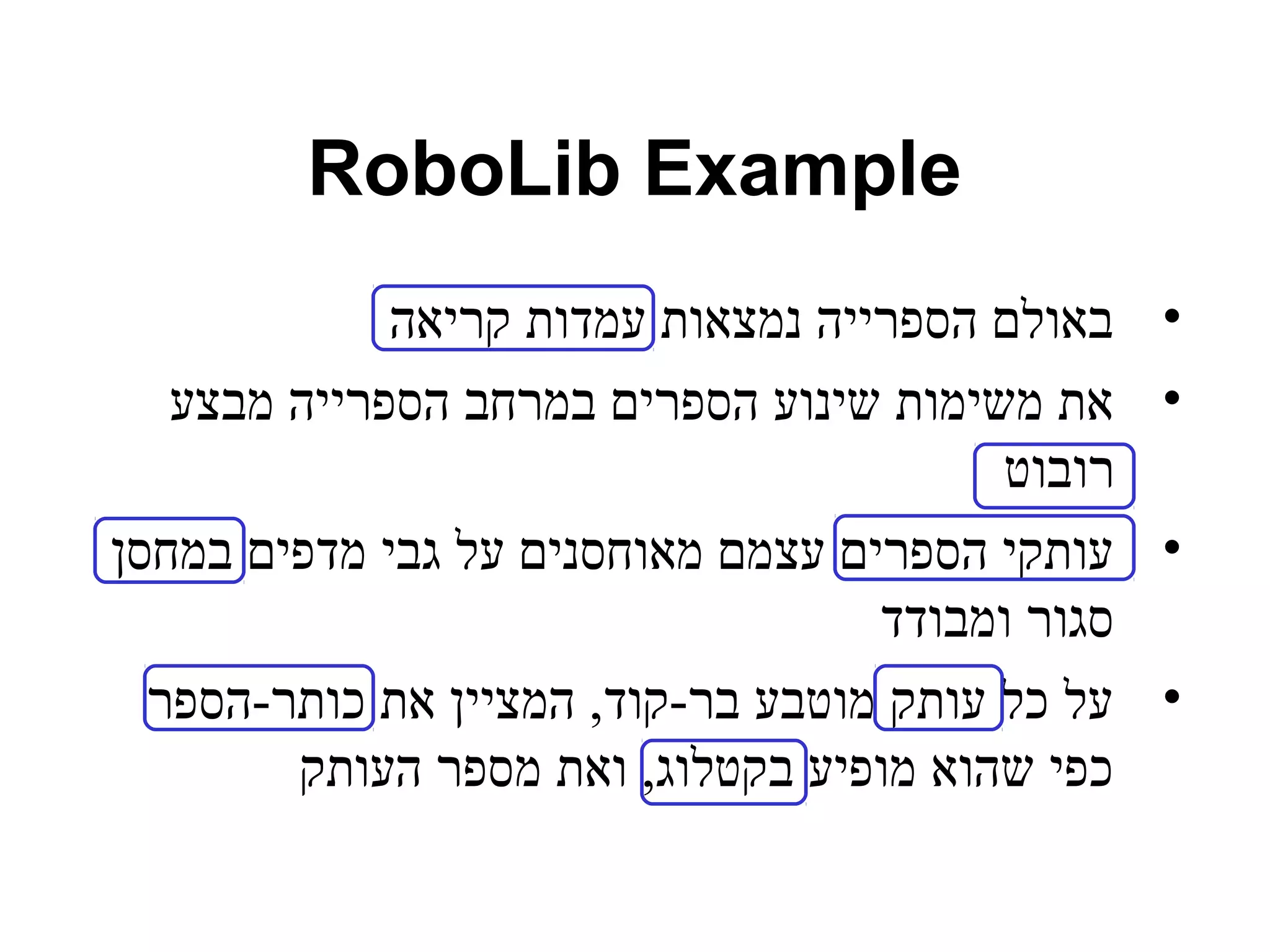
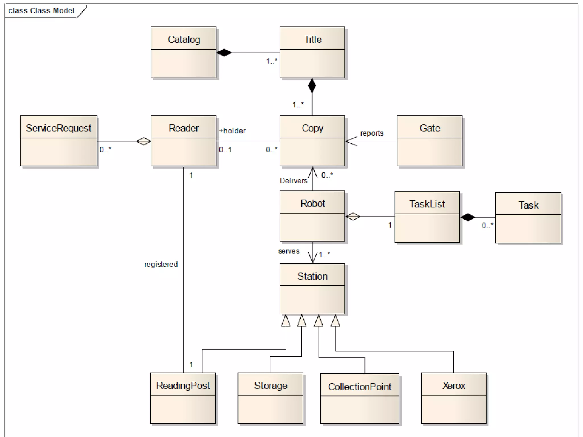
Real-life example of RoboLib system functionality concerning book circulation in a library.
Practical tips for designing UML diagrams without overcomplicating the models.
Brief mention of a backup related to UML class diagrams.
Technique for identifying analysis classes from system border, data, and control logic perspectives.
Explanation of boundary classes that facilitate interaction between system and environment and their dependency.
Entity classes designed to model key concepts in the system that are environment-independent.
Role of control classes in coordinating behaviors of use cases and their function in system architecture.
Agenda
• Whatis a Class Diagram?
• Essential Elements of a UML Class
Diagram
• Tips
UML Class Diagrams 2
3.
What is aClass Diagram?
• A Class Diagram is a diagram describing
the structure of a system
• shows the system's
• classes
• Attributes
• operations (or methods),
• Relationships among the classes.
UML Class Diagrams 3
4.
Essential Elements ofa
UML Class Diagram
UML Class Diagrams 4
• Class
• Attributes
• Operations
• Relationships
– Associations
– Generalization
– Realization
– Dependency
• Constraint Rules and Notes
5.
Class
• Describesa set of objects having similar:
– Attributes (status)
– Operations (behavior)
– Relationships with other classes
• Attributes and operations may
– have their visibility marked:
– "+" for public
– "#" for protected
– "−" for private
– "~" for package
Window
size: Size
visibility: boolean
display()
hide()
Class
Name
Attributes
Operations
UML Class Diagrams 5
6.
Associations
• Anassociation between two classes indicates that
objects at one end of an association “recognize”
objects at the other end and may send messages to
them.
• Example: “An Employee works for a Company”
Employee Company
UML Class Diagrams 6
7.
Associations (cont.)
StaffMemberStudent
1..* instructs *
Role
*
UML Class Diagrams 7
instructor
Association
name
Role
name
Multiplicity
Navigable
(uni-directional)
association
Courses
pre -
requisites
Reflexive 0..3
association
8.
Associations (cont.)
•To clarify its meaning, an association may be
named.
– The name is represented as a label placed midway
along the association line.
– Usually a verb or a verb phrase.
• A role is an end of an association where it
connects to a class.
– May be named to indicate the role played by the class
attached to the end of the association path.
• Usually a noun or noun phrase
• Mandatory for reflexive associations
UML Class Diagrams 8
9.
Associations (cont.)
MultiplicityIndicators
UML Class Diagrams 9
• Multiplicity
– the number of objects that participate in the association.
– Indicates whether or not an association is mandatory.
Exactly one 1
Zero or more (unlimited) * (0..*)
One or more 1..*
Zero or one (optional association) 0..1
Specified range 2..4
Multiple, disjoint ranges 2, 4..6, 8
10.
Aggregation
• Aspecial form of association that models a
whole-part relationship between an
aggregate (the whole) and its parts.
– Models a “is a part-part of” relationship.
Car 2..* Door 1..* House
Whole Part
UML Class Diagrams 10
11.
Aggregation (cont.)
UMLClass Diagrams 11
• Aggregation tests:
– Is the phrase “part of” used to describe the relationship?
• A door is “part of” a car
– Are some operations on the whole automatically applied to its
parts?
• Move the car, move the door.
– Are some attribute values propagated from the whole to all or
some of its parts?
• The car is blue, therefore the door is blue.
– Is there an intrinsic asymmetry to the relationship where one class
is subordinate to the other?
• A door is part of a car. A car is not part of a door.
12.
Composition
• Astrong form of aggregation
– The whole is the sole owner of its part.
• The part object may belong to only one whole
– Multiplicity on the whole side must be zero or one.
– The life time of the part is dependent upon the whole.
• The composite must manage the creation and destruction of its
parts.
1
Circle Point
3..*
Circle
UML Class Diagrams 12
Polygon
Point
13.
Generalization
• Indicatesthat objects of the specialized
class (subclass) are substitutable for objects
of the generalized class (super-class).
– “is kind of” relationship.
Shape
{abstract}
Circle
Super
Class
Sub
Class
An abstract
class
Generalization
relationship
UML Class Diagrams 13
{abstract} is a
tagged value that
indicates that the
class is abstract.
The name of an
abstract class should
be italicized
14.
Generalization
• Asub-class inherits from its super-class
UML Class Diagrams 14
– Attributes
– Operations
– Relationships
• A sub-class may
– Add attributes and operations
– Add relationships
– Refine (override) inherited operations
• A generalization relationship may not be used to
model interface implementation.
15.
Realization
• Arealization relationship indicates that one
class implements a behavior specified by
another class (an interface or protocol).
• An interface can be realized by many
classes.
• A class may realize many interfaces.
LinkedList <<interface>>
List ArrayList
UML Class Diagrams 15
16.
Dependency
• Dependencyis a weaker form of relationship which
indicates that one class depends on another because it uses
it at some point in time.
• One class depends on another if the independent class is a
parameter variable or local variable of a method of the
dependent class.
• This is different from an association, where an attribute of
the dependent class is an instance of the independent class.
Iterator Vector <<friend>>
UML Class Diagrams 16
17.
Constraint Rules andNotes
• Constraints and notes annotate among other
things associations, attributes, operations and
classes.
• Constraints are semantic restrictions noted as
Boolean expressions.
– UML offers many pre-defined constraints.
UML Class Diagrams 17
Customer
id: long { value > 0 }
1 * Order
{ total < $50 }
may be
canceled
Constraint Note
18.
Traffic Violation ReportSystem Example
TrafficReport
TrafficPoliceman id : long
Violation
Offender
UML Class Diagrams 18
Policeman
id : long
name : String
rank : int
<<abstract>>
description : String
id : long
description : String
name : String
id : long
1..* 1
reports of
1..*
1 issues *
occuredAt : Date
19.
Analysis Classes Elicitation
• Consider main perspectives of the system
• Interface between the system and its actors
– Protocols for information exchange
– Don’t concentrate on visual aspects
• Data the system uses
– The core of the system, key concepts
• The system logic
– Controls and coordinates the behavior
– Delegates the work to other classes
– Decouples interface and data classes
UML Class Diagrams 19
20.
RoboLib Example
•באולם הספרייה נמצאות עמדות קריאה
• את משימות שינוע הספרים במרחב הספרייה מבצע
רובוט
• עותקי הספרים עצמם מאוחסנים על גבי מדפים במחסן
סגור ומבודד
• על כל עותק מוטבע בר-קוד, המציין את כותר-הספר
כפי שהוא מופיע בקטלוג, ואת מספר העותק
22.
Tips
• Don’ttry to use all the various notations.
• Don’t draw models for everything,
concentrate on the key areas.
UML Class Diagrams 22
Analysis Classes
•A technique for finding analysis classes
which uses three different perspectives of
the system:
• The boundary between the system and its actors
(Boundary)
• The information the system uses (Entity)
• The control logic of the system (Control)
UML Class Diagrams 24
25.
Boundary Classes
•Models the interaction between the
system’s surroundings and its inner
workings
– User interface classes
• Concentrate on what information is presented to the
user
• Don’t concentrate on user interface details
– System / Device interface classes
• Concentrate on what protocols must be defined.
Don’t concentrate on how the protocols are
implemented
UML Class Diagrams 25
26.
Boundary Classes (cont.)
• Boundary classes are environment
dependent:
– UI dependent
– Communication protocol dependent
UML Class Diagrams 26
27.
Entity Classes
•Models the key concepts of the system
• Usually models information that is persistent
• Contains the logic that solves the system problem
• Is environment independent
• Can be used in multiple use cases
For example: Violation, Report, Offender.
UML Class Diagrams 27
28.
Control Classes
•Controls and coordinates the behavior of a
use case
• Delegates the work of the use case to
classes
– A control class should tell other classes to do
something and should never do anything except
for directing
• Control classes decouple boundary and
entity classes
• Often, there is one control class per use case
UML Class Diagrams 28