
Recommended
Recommended
More Related Content
More from ze3xiandiao
More from ze3xiandiao (20)
Recently uploaded
Recently uploaded (13)
Caterpillar Cat 621E WHEEL SCRAPER (Prefix 6BB) Service Repair Manual Instant Download.pdf
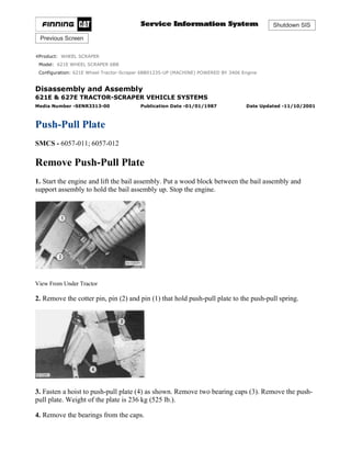
- 1. Shutdown SIS Previous Screen Product: WHEEL SCRAPER Model: 621E WHEEL SCRAPER 6BB Configuration: 621E Wheel Tractor-Scraper 6BB01235-UP (MACHINE) POWERED BY 3406 Engine Disassembly and Assembly 621E & 627E TRACTOR-SCRAPER VEHICLE SYSTEMS Media Number -SENR3313-00 Publication Date -01/01/1987 Date Updated -11/10/2001 Push-Pull Plate SMCS - 6057-011; 6057-012 Remove Push-Pull Plate 1. Start the engine and lift the bail assembly. Put a wood block between the bail assembly and support assembly to hold the bail assembly up. Stop the engine. View From Under Tractor 2. Remove the cotter pin, pin (2) and pin (1) that hold push-pull plate to the push-pull spring. 3. Fasten a hoist to push-pull plate (4) as shown. Remove two bearing caps (3). Remove the push- pull plate. Weight of the plate is 236 kg (525 lb.). 4. Remove the bearings from the caps. 1/2(W) w 2021/4/3 https://127.0.0.1/sisweb/sisweb/techdoc/techdoc_print_page.jsp?returnurl=/sisweb/siswe...
- 2. Install Push-Pull Plate 1. Install the bearings in caps (2). 2. Fasten a hoist to push-pull plate (1) and put it in position on the support assembly. Install the two caps. View From Under Tractor 3. Install pin (3). Install the pin and cotter pin that hold pin (3) in position. Copyright 1993 - 2021 Caterpillar Inc. All Rights Reserved. Private Network For SIS Licensees. Sat Apr 3 16:39:22 UTC+0800 2021 2/2(W) w 2021/4/3 https://127.0.0.1/sisweb/sisweb/techdoc/techdoc_print_page.jsp?returnurl=/sisweb/siswe...
- 3. Shutdown SIS Previous Screen Product: WHEEL SCRAPER Model: 621E WHEEL SCRAPER 6BB Configuration: 621E Wheel Tractor-Scraper 6BB01235-UP (MACHINE) POWERED BY 3406 Engine Disassembly and Assembly 621E & 627E TRACTOR-SCRAPER VEHICLE SYSTEMS Media Number -SENR3313-00 Publication Date -01/01/1987 Date Updated -11/10/2001 Push-Pull Spring SMCS - 6262-011; 6262-012; 6262-015; 6262-016 Remove Push-Pull Spring Start By: a. remove push-pull plate 1. Fasten a hoist to push-pull spring (2) as shown. 2. Remove eight bolts (1) and remove the spring. The weight of the spring is 45 kg (100 lb.). Install Push-Pull Spring 1. Put push-pull spring (1) in position on the support assembly. Install the bolts that hold it. End By: 1/4(W) w 2021/4/3 https://127.0.0.1/sisweb/sisweb/techdoc/techdoc_print_page.jsp?returnurl=/sisweb/siswe...
- 4. a. install push-pull plate Disassemble Push-Pull Spring Start By: a. remove push-pull spring 1. Remove nut (1) and the washer with tool (A). 2. Pull rod (5) out of plate assembly (4), ten spring discs (3) and plate assembly (2). 3. Remove four bolts (6) and lockwashers. 4. Remove pad (7) and the bushing from plate assembly (2). Assemble Push-Pull Spring 2/4(W) w 2021/4/3 https://127.0.0.1/sisweb/sisweb/techdoc/techdoc_print_page.jsp?returnurl=/sisweb/siswe...
- 5. 1. Install bushing (2) in plate assembly (1). Put pad (3) in position on the plate assembly and install the four bolts that hold it. 2. Install plate assembly (5), ten spring discs (4) and plate assembly (7) on rod (6) as shown. 3. Install the washer and nut that holds the unit together. Do not tighten the nut at this time. 4. Put the push-pull spring on wood blocks as shown. Tighten nut (8) with tool (A). 5. Put a straight ruler against the ten spring discs. Make sure all the discs are in contact with the ruler. If the discs are not in contact with the ruler, loosen nut (8) and make an adjustment to the spring discs. The maximum amount of distance that the spring discs can be away from the ruler at the center of the spring must not be more than 3.05 mm (.12 in.). End By: a. install push-pull spring 3/4(W) w 2021/4/3 https://127.0.0.1/sisweb/sisweb/techdoc/techdoc_print_page.jsp?returnurl=/sisweb/siswe...
- 6. Copyright 1993 - 2021 Caterpillar Inc. All Rights Reserved. Private Network For SIS Licensees. Sat Apr 3 16:40:18 UTC+0800 2021 4/4(W) w 2021/4/3 https://127.0.0.1/sisweb/sisweb/techdoc/techdoc_print_page.jsp?returnurl=/sisweb/siswe...
- 7. Shutdown SIS Previous Screen Product: WHEEL SCRAPER Model: 621E WHEEL SCRAPER 6BB Configuration: 621E Wheel Tractor-Scraper 6BB01235-UP (MACHINE) POWERED BY 3406 Engine Disassembly and Assembly 621E & 627E TRACTOR-SCRAPER VEHICLE SYSTEMS Media Number -SENR3313-00 Publication Date -01/01/1987 Date Updated -11/10/2001 Ejector Cylinder SMCS - 5305-011; 5305-012 Remove Ejector Cylinder 1. Start the engine and lift the bowl until it is level. Put wood blocks (1) under the bowl to hold it in position. 2. Retract the ejector fully. Stop the engine. NOTE: Oil will drain out of the ejector cylinder when the hydraulic hoses are disconnected from it. Put plugs in the hoses and cylinder as they are disconnected. 1/6(W) w 2021/4/3 https://127.0.0.1/sisweb/sisweb/techdoc/techdoc_print_page.jsp?returnurl=/sisweb/siswe...
- 8. View From Under Scraper 3. Disconnect hose (4) from the rod end of the cylinder. 4. Disconnect hose (2) from the tube assembly. Remove the clip from the tube assembly. 5. Remove tube assembly (3). View From Under Scraper Typical Example 6. Put tool (A) and a lifting strap around the head end of the ejector cylinder as shown. Tool (A) will hold the cylinder up when the rear pin that holds the cylinder is removed. 7. Remove two bolts (6) and lock, washer (5) and the pin that holds the head end of the cylinder in position. View From Under Scraper 2/6(W) w 2021/4/3 https://127.0.0.1/sisweb/sisweb/techdoc/techdoc_print_page.jsp?returnurl=/sisweb/siswe...
- 9. 8. Put wood blocks (7) on the crossmember of the bowl as shown. Make sure the blocks are under the ejector cylinder. 9. Lower the cylinder on the wood blocks with tool (A). Remove tool (A) from around the cylinder. 10. Install lifting straps around the ejector as shown. 11. Install tool (A) on the apron and the lifting straps as shown. When the ejector is pulled forward with tool (A), make sure the cylinder does not fall off of the wood blocks. Keep away from the area of the ejector cylinder when the ejector is pulled forward. 12. Pull the ejector forward with tool (A). Do not pull the ejector too far forward. The ejector cylinder will fall off the wood blocks on the crossmember. 13. After the ejector cylinder is out from under the power pack, use wood blocks (7) as a support for the center of the cylinder as shown. 14. Fasten tool (A) and lifting straps to the ejector overflow guard. Fasten tool (A) and the lifting straps to the ejector cylinder as shown. 15. Remove two bolts (8), lock and washer (9) and the pin that holds the ejector cylinder to the ejector. 16. Lift the cylinder with tool (A) and turn it 90° in the bowl. Lower the cylinder on the frame of the ejector. Remove tool (A) and the lifting straps. 3/6(W) w 2021/4/3 https://127.0.0.1/sisweb/sisweb/techdoc/techdoc_print_page.jsp?returnurl=/sisweb/siswe...
- 10. 17. Fasten a hoist to ejector cylinder (10) and remove it from the machine. The weight of the cylinder is 205 kg (456 lb.). Install Ejector Cylinder 1. Fasten a hoist to ejector cylinder (1) and put it in position on the frame of the ejector as shown. Remove the hoist. 4/6(W) w 2021/4/3 https://127.0.0.1/sisweb/sisweb/techdoc/techdoc_print_page.jsp?returnurl=/sisweb/siswe...
- 11. 2. Fasten tool (A) and lifting straps to the ejector overflow guard. Fasten the lifting straps to the ejector cylinder. Lift the cylinder and put it on wood blocks (3) as shown. Move the cylinder into position until the hole in the rod end is in alignment with the blocks in the bracket on the ejector. Install pin (2), the washer, lock and two bolts that hold pin (2) in position. 3. Put wood blocks on the crossmember of the bowl at the head end of the cylinder. 4. Lower the cylinder onto the wood blocks. Remove tool (A) and the lifting straps from the cylinder. Keep away from the area of the ejector cylinder when it is pulled into position under the power pack with tool (A). The cylinder can fall off the wood blocks. View From Under Scraper 5. Fasten tool (A) to the rear of the ejector frame and to the frame of the bowl. Pull the ejector and cylinder to the rear until the hole in the head end of the cylinder is in alignment with the holes in the bracket in the frame of the bowl. Remove tool (A). View From Under Scraper 5/6(W) w 2021/4/3 https://127.0.0.1/sisweb/sisweb/techdoc/techdoc_print_page.jsp?returnurl=/sisweb/siswe...
- 12. 6. Fasten tool (A) and a lifting strap around the head end of the cylinder as shown. Tool (A) is used to move the cylinder up or down. 7. Lift or lower the cylinder until pin (4) can be installed. Install the pin, washer, lock and two bolts that hold the pin in position. Remove tool (A). Remove all wood blocks. View From Under Scraper 8. Install tube assembly (7) and the clip. 9. Connect hose (6) to the cylinder. 10. Connect hose (5) to the tube assembly. 11. Start the engine and lift the bowl. Remove the wood blocks from under it. 12. Move the ejector fully forward and back to the rear several times to release the air in the cylinder. 13. Fill the hydraulic tank with oil to the correct level. See the Maintenance Guide. Copyright 1993 - 2021 Caterpillar Inc. All Rights Reserved. Private Network For SIS Licensees. Sat Apr 3 16:41:14 UTC+0800 2021 6/6(W) w 2021/4/3 https://127.0.0.1/sisweb/sisweb/techdoc/techdoc_print_page.jsp?returnurl=/sisweb/siswe...
- 13. Shutdown SIS Previous Screen Product: WHEEL SCRAPER Model: 621E WHEEL SCRAPER 6BB Configuration: 621E Wheel Tractor-Scraper 6BB01235-UP (MACHINE) POWERED BY 3406 Engine Disassembly and Assembly 621E & 627E TRACTOR-SCRAPER VEHICLE SYSTEMS Media Number -SENR3313-00 Publication Date -01/01/1987 Date Updated -11/10/2001 Ejector Carrier Rollers (Lower Front) SMCS - 6229-011; 6229-012 Remove Ejector Carrier Rollers (Lower Front) 1. Start the engine and move the ejector to the rear all the way. Stop the engine. 2. Put tool (A) in position under the bracket on the ejector as shown. Tool (A) is used as a support. 3. Remove lock bolt (1) and the nut that holds the ejector carrier roller in position. 4. Turn shaft (2) until the roller is clear of the bowl. Remove ejector carrier roller (3). Install Ejector Carrier Rollers (Lower Front) 1/2(W) w 2021/4/3 https://127.0.0.1/sisweb/sisweb/techdoc/techdoc_print_page.jsp?returnurl=/sisweb/siswe...
- 14. 1. Put ejector carrier roller (1) in position in the bracket on the ejector as shown. 2. Make an adjustment to the ejector carrier roller for the correct distance between the ejector and the bottom of the bowl as follows: a. Turn shaft (2) until the minimum distance between the ejector and the bottom of the bowl is 0.8 mm (.03 in.). The maximum clearance between the ejector and the bottom of the bowl must not be more than 12.7 mm (.50 in.). 3. Install the lock bolt and nut in the bracket. 4. Remove tool (A). Copyright 1993 - 2021 Caterpillar Inc. All Rights Reserved. Private Network For SIS Licensees. Sat Apr 3 16:42:09 UTC+0800 2021 2/2(W) w 2021/4/3 https://127.0.0.1/sisweb/sisweb/techdoc/techdoc_print_page.jsp?returnurl=/sisweb/siswe...
- 15. Shutdown SIS Previous Screen Product: WHEEL SCRAPER Model: 621E WHEEL SCRAPER 6BB Configuration: 621E Wheel Tractor-Scraper 6BB01235-UP (MACHINE) POWERED BY 3406 Engine Disassembly and Assembly 621E & 627E TRACTOR-SCRAPER VEHICLE SYSTEMS Media Number -SENR3313-00 Publication Date -01/01/1987 Date Updated -11/10/2001 Ejector Guide Rollers SMCS - 6230-011; 6230-012 Remove Ejector Guide Rollers 1. Start the engine and move the ejector forward all the way. Stop the engine. 2. Remove lock bolt (1) and nut that hold the guide roller in position. 3. Turn the shaft in the guide roller until there is clearance between the rail assembly and roller. Remove ejector guide roller (2). 1/2(W) w 2021/4/3 https://127.0.0.1/sisweb/sisweb/techdoc/techdoc_print_page.jsp?returnurl=/sisweb/siswe...
- 16. Install Ejector Guide Rollers 1. Put the ejector guide bolts (1) in position in the bracket on the ejector. 2. Make an adjustment to the ejector guide roller for the correct distance between the sides of the ejector and the sides of the bowl as follows: a. Turn shaft (3) until the minimum distance between the side of the ejector and the side of the bowl is 3 mm (.12 in.). The maximum clearance between the side of the ejector and the side of the bowl must not be more than 19 mm (.75 in.). 3. Install lock bolt (2) and the nut. Copyright 1993 - 2021 Caterpillar Inc. All Rights Reserved. Private Network For SIS Licensees. Sat Apr 3 16:43:05 UTC+0800 2021 2/2(W) w 2021/4/3 https://127.0.0.1/sisweb/sisweb/techdoc/techdoc_print_page.jsp?returnurl=/sisweb/siswe...
- 17. Shutdown SIS Previous Screen Product: WHEEL SCRAPER Model: 621E WHEEL SCRAPER 6BB Configuration: 621E Wheel Tractor-Scraper 6BB01235-UP (MACHINE) POWERED BY 3406 Engine Disassembly and Assembly 621E & 627E TRACTOR-SCRAPER VEHICLE SYSTEMS Media Number -SENR3313-00 Publication Date -01/01/1987 Date Updated -11/10/2001 Ejector Rollers (Rear) SMCS - 6229; 6230-011; 6230-012 Remove Ejector Rollers (Rear) 1. Put tool (A) and a block of wood under the rear of the ejector, and lift the ejector until the weight is off the rear rollers. 2. Remove cover (1) from the top of the roller, and remove bolt (2) that holds the roller shaft to the ejector frame. 1/4(W) w 2021/4/3 https://127.0.0.1/sisweb/sisweb/techdoc/techdoc_print_page.jsp?returnurl=/sisweb/siswe...
- 18. 3. Remove cotter pin (3) and nut (4) from the roller shaft. 4. Use a brass bar (5) and a hammer to push roller shaft (6) down through the roller. Remove roller shaft (6) and roller (7) from the ejector. 5. Use tooling (B) to remove bearing cup (8) from the top of the roller. 5. Use tooling (C) to remove the bearing cup, bearing cone and seal from the roller. Install Ejector Rollers (Rear) 2/4(W) w 2021/4/3 https://127.0.0.1/sisweb/sisweb/techdoc/techdoc_print_page.jsp?returnurl=/sisweb/siswe...
- 19. 1. Use tooling (B) to install bearing cups (4) in the roller. 2. Install bearing cone (3) in the bottom of the roller. 3. Use tooling (B) to install seal (2) in the roller with the spring loaded lip in as shown. 4. Put the roller in position on the ejector, and install roller shaft (1) up through the ejector and roller. Install the bolt that holds the roller shaft to the ejector. 5. Fill the roller with 1P808 General Purpose Lubricant. 6. Install the top bearing cone (5), washer (6) and nut (7) on the roller shaft. Tighten nut (7) until the roller stops when turned by hand. Then loosen nut (7) until the cotter pin that holds the nut in place can be installed. 3/4(W) w 2021/4/3 https://127.0.0.1/sisweb/sisweb/techdoc/techdoc_print_page.jsp?returnurl=/sisweb/siswe...
- 20. 7. Turn roller shaft (1) until the rear of the ejector is in the center of the ejector rails in the bowl and dimension (X) is 1.57 mm (.062 in.) at the tightest place on the rails. Tighten bolt (8) to hold the roller shaft in place. Remove tool (A) and the block from under the ejector. NOTE: The other ejector rollers can be removed and installed in the same way. Make an adjustment to the side and front rollers as follows: 8. With bolt (9) loose, turn roller shaft (10) until the ejector is in the center of the bowl and dimension (Y) is 1.57 mm (.062 in.) at the tightest place on the rails. Tighten bolt (9) to hold the roller shaft in place. 9. With bolt (11) loose, turn the roller shaft until the ejector is parallel to the floor of the bowl and dimension (Z) is 3.18 mm (.125 in.) at the tightest place along the floor. Tighten bolt (11) to hold the roller shaft in place. Copyright 1993 - 2021 Caterpillar Inc. All Rights Reserved. Private Network For SIS Licensees. Sat Apr 3 16:44:01 UTC+0800 2021 4/4(W) w 2021/4/3 https://127.0.0.1/sisweb/sisweb/techdoc/techdoc_print_page.jsp?returnurl=/sisweb/siswe...
- 21. Shutdown SIS Previous Screen Product: WHEEL SCRAPER Model: 621E WHEEL SCRAPER 6BB Configuration: 621E Wheel Tractor-Scraper 6BB01235-UP (MACHINE) POWERED BY 3406 Engine Disassembly and Assembly 621E & 627E TRACTOR-SCRAPER VEHICLE SYSTEMS Media Number -SENR3313-00 Publication Date -01/01/1987 Date Updated -11/10/2001 Ejector Carrier Rollers (Lower Front) And Ejector Guide Rollers SMCS - 6229; 6230-016; 6330-015 Disassemble Ejector Carrier Rollers (Lower Front) And Ejector Guide Rollers Start By: a. remove ejector carrier rollers (lower) b. remove ejector guide rollers 1. Remove four bolts (1), cap (2) and the gasket from the roller. 2. Remove nut (3), lock and washer (4) from the shaft. 3. Remove bearing cone (5) from the roller. 1/5(W) w 2021/4/3 https://127.0.0.1/sisweb/sisweb/techdoc/techdoc_print_page.jsp?returnurl=/sisweb/siswe...
- 22. 4. Remove shaft (6), seal (7) and the bearing cone from the roller. 5. Remove bearing cup (8) from the roller with a hammer and a brass punch. 6. Remove bearing cup (9) from the roller with a hammer and a brass punch. Assemble Ejector Carrier Rollers (Lower Front) And Ejector Guide Rollers 2/5(W) w 2021/4/3 https://127.0.0.1/sisweb/sisweb/techdoc/techdoc_print_page.jsp?returnurl=/sisweb/siswe...
- 23. 1. Install the large bearing cup in the roller with tooling (A). Install the bearing cup until it makes contact with the counterbore in the roller. 2. Turn the roller over. Install the small bearing cup in the roller with tool (A). Install the bearing cup until it makes contact with the bottom of the counterbore in the roller. 3. Put 5P960 Multipurpose Grease on the large bearing cone. Install bearing cone (1) in the roller. 4. Install the lip type seal in the roller with tooling (B). Install the seal with the lip toward the inside of the roller and until the seal makes contact with the bottom of the counterbore in the roller. 5. Put 5P960 Multipurpose Grease on the lip of the seal. 3/5(W) w 2021/4/3 https://127.0.0.1/sisweb/sisweb/techdoc/techdoc_print_page.jsp?returnurl=/sisweb/siswe...
- 24. 6. Install shaft (2) in the roller as shown. 7. Put 5P960 Multipurpose Grease inside the roller and on bearing cone (4). Install bearing cone and washer (3). 8. Install nut (5). tighten the nut until the roller will not turn by hand. Loosen the nut 1/16 of one turn. 9. Install gasket (8) and cap (6). Install bolts (7) that hold the cap. End By: a. install ejector carrier rollers (lower) b. install ejector guide rollers 4/5(W) w 2021/4/3 https://127.0.0.1/sisweb/sisweb/techdoc/techdoc_print_page.jsp?returnurl=/sisweb/siswe...
- 25. Shutdown SIS Previous Screen Product: WHEEL SCRAPER Model: 621E WHEEL SCRAPER 6BB Configuration: 621E Wheel Tractor-Scraper 6BB01235-UP (MACHINE) POWERED BY 3406 Engine Disassembly and Assembly 621E & 627E TRACTOR-SCRAPER VEHICLE SYSTEMS Media Number -SENR3313-00 Publication Date -01/01/1987 Date Updated -11/10/2001 Horizontal Cushion Hitch Bearings SMCS - 6229; 6230-016; 6330-015 Remove Horizontal Cushion Hitch Bearings Start By: a. remove cushion hitch 1. Remove two forward horizontal hitch bearings (1) with tooling (A) as follows: a. Remove one bearing with tooling (A) as shown. b. Install tooling (A) on the other bearing support as in Step 1a. c. Remove the other bearing with tooling (A). 1/6(W) w 2021/4/3 https://127.0.0.1/sisweb/sisweb/techdoc/techdoc_print_page.jsp?returnurl=/sisweb/siswe...
- 26. 2. Remove two bearings (2) and two seal rings (3) from the cushion hitch. 3. Remove washer (4) from each bearing (2). 4. Remove two bearings (5) from the cushion hitch. 5. Remove two bearings (6) from hitch rear support with tooling (A) as follows: a. Remove one bearing (6) with tooling (A) as shown. b. Install tooling (A) on the other bearing support as in Step a. c. Remove the other bearing (6) with tooling (A). 2/6(W) w 2021/4/3 https://127.0.0.1/sisweb/sisweb/techdoc/techdoc_print_page.jsp?returnurl=/sisweb/siswe...
- 27. 6. Remove two seals (7) from forward horizontal hitch support. 7. Remove two bearings from horizontal hitch forward support with tooling (A). Install Horizontal Cushion Hitch Bearings NOTE: Lower the temperture of all cushion hitch horizontal bearings before installation. 3/6(W) w 2021/4/3 https://127.0.0.1/sisweb/sisweb/techdoc/techdoc_print_page.jsp?returnurl=/sisweb/siswe...
- 28. 1. Install two forward horizontal cushion hitch bearings (1) in cushion hitch with tooling (A) as follows: a. Install one bearing (1) with tooling (A) as shown. b. Install tooling (A) on the other bearing support as in Step 1a. c. Install the other bearing (1) with tooling (A). 2. Install two rear cushion hitch horizontal bearings (2) in cushion hitch with tooling (B). 3. Install two seal rings (3) on cushion hitch rear horizontal bearings (2) with the chamfered edge of the seal ring (3) toward the outside of the cushion hitch bearing support. NOTE: Put a small amount of 5P960 Multipurpose Grease on both sides of the brass washer (4) before it is installed in bearing (5). 4/6(W) w 2021/4/3 https://127.0.0.1/sisweb/sisweb/techdoc/techdoc_print_page.jsp?returnurl=/sisweb/siswe...
- 29. 4. Install brass washer (4) in each of two bearings (5) with chamfered side of brass washer (4) toward the inside of bearing (5). 5. Install two bearings (5) over bearings (2) and ring seals (3). 6. Install two bearings (6) in cushion hitch rear horizontal supports with tooling (B) as follows: a. Install one bearing (6) with tooling (B) as shown. b. Install tooling (B) on the other bearing support as in Step 6a. c. Install the other bearing (6) with tooling (B). 7. Install two bearings in cushion hitch forward horizontal support (7) with tooling (A) as follows: 5/6(W) w 2021/4/3 https://127.0.0.1/sisweb/sisweb/techdoc/techdoc_print_page.jsp?returnurl=/sisweb/siswe...
- 30. a. Pull rear bearing through support (7) with tooling (A) until the bearing is even with the rear seal counterbore in support (7). b. Install tooling (B) on the other bearing support as in Step 6a. c. Install the other bearing (6) with tooling (B). 7. Install two bearings in cushion hitch forward horizontal support (7) with tooling (A) as follows: a. Pull rear bearing through support (7) with tooling (A) until the bearing is even with the rear seal counterbore in support (7). b. Pull forward bearing into support (7) with tooling (A) until the bearing is even with the forward seal counterbore in support (7). 8. Install two lip type seals in support (7) with tooling (C). Install the seals with the lips toward the outside of the support (7) and until they make contact with the bottom of the seal counterbores in support (7). End By: a. install cushion hitch Copyright 1993 - 2021 Caterpillar Inc. All Rights Reserved. Private Network For SIS Licensees. Sat Apr 3 16:45:52 UTC+0800 2021 6/6(W) w 2021/4/3 https://127.0.0.1/sisweb/sisweb/techdoc/techdoc_print_page.jsp?returnurl=/sisweb/siswe...
- 31. Suggest: If the above button click is invalid. Please download this document first, and then click the above link to download the complete manual. Thank you so much for reading
- 32. Shutdown SIS Previous Screen Product: WHEEL SCRAPER Model: 621E WHEEL SCRAPER 6BB Configuration: 621E Wheel Tractor-Scraper 6BB01235-UP (MACHINE) POWERED BY 3406 Engine Disassembly and Assembly 621E & 627E TRACTOR-SCRAPER VEHICLE SYSTEMS Media Number -SENR3313-00 Publication Date -01/01/1987 Date Updated -11/10/2001 Steering Link Assemblies SMCS - 4305-011; 4305-012 Remove Steering Link Assemblies NOTE: The steering link assemblies on the left and right sides of the machine are removed the same way. The only difference is the steering cylinder (servo-sender) must be disconnected on the left side of the machine. 1. Remove the four bolts, washers and two yokes (2) that hold pin assembly (1) in position. 2. Remove pin assembly (1) and make a separation of the steering cylinder rod end and the two link assemblies. 1/6(W) w 2021/4/3 https://127.0.0.1/sisweb/sisweb/techdoc/techdoc_print_page.jsp?returnurl=/sisweb/siswe...
- 33. 3. Fasten a hoist to link assembly (3). Remove the four bolts, washers and two yokes (5) that hold pin assembly (4) in position. Remove the pin assembly. Remove the link assembly. The weight of the link assembly is 41 kg (90 lb.). 4. Remove bolt (6) from the rod end of the steering cylinder (servo-sender). 5. Fasten a hoist to link assembly (8). Remove the four bolts, washers and two yokes (9) that hold pin assembly (7) in position. Remove the pin assembly. Remove the link assembly. The weight of the link assembly is 45 kg (100 lb.). 6. Remove the bearings from the two steering link assemblies with tooling (A). 2/6(W) w 2021/4/3 https://127.0.0.1/sisweb/sisweb/techdoc/techdoc_print_page.jsp?returnurl=/sisweb/siswe...