
Recommended
More Related Content
Similar to Caterpillar Cat D7G TRACK-TYPE TRACTOR (Prefix 44W) Service Repair Manual Instant Download.pdf
Similar to Caterpillar Cat D7G TRACK-TYPE TRACTOR (Prefix 44W) Service Repair Manual Instant Download.pdf (20)
More from ze3xiandiao
More from ze3xiandiao (20)
Recently uploaded
Recently uploaded (20)
Caterpillar Cat D7G TRACK-TYPE TRACTOR (Prefix 44W) Service Repair Manual Instant Download.pdf
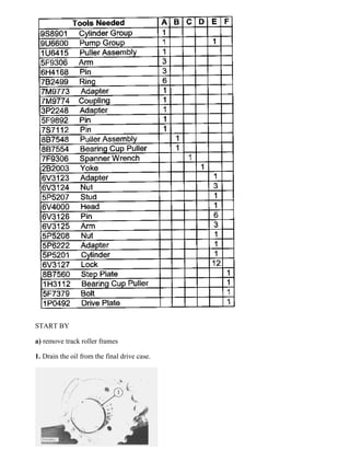
- 1. START BY a) remove track roller frames 1. Drain the oil from the final drive case. 4/19 D7G LGP TRACTOR / POWERSHIFT / 44W00001-UP (MACHINE) POWERED B... 2021/8/17 https://127.0.0.1/sisweb/sisweb/techdoc/techdoc_print_page.jsp?returnurl=/sis...
- 2. 2. Remove cap (1) and the gasket. 3. Remove lock (2) and nut (3) from the sprocket shaft. 4. Remove retainer (4) and the shims from the sprocket shaft. 5. Remove support (5) from the holder assembly. Remove the seal ring from the holder assembly. 6. Remove seal (6) and bearing (7) from support (5). 7. Remove the nut and bolt (8). Remove lock (9) from the holder assembly. 5/19 D7G LGP TRACTOR / POWERSHIFT / 44W00001-UP (MACHINE) POWERED B... 2021/8/17 https://127.0.0.1/sisweb/sisweb/techdoc/techdoc_print_page.jsp?returnurl=/sis...
- 3. NOTICE Do not use more than 50 ton (445 kn) of pressure to remove the holder assembly. 8. Install tooling (A) as shown and loosen holder assembly (10) from the taper on the sprocket shaft. 9. Remove tooling (A). Fasten a hoist and remove holder assembly (10) and adjusting nut (11) as a unit. The weight is approximately 80 lb. (36 kg.). 10. Remove Duo-Cone seal (12) from adjusting nut (11). 6/19 D7G LGP TRACTOR / POWERSHIFT / 44W00001-UP (MACHINE) POWERED B... 2021/8/17 https://127.0.0.1/sisweb/sisweb/techdoc/techdoc_print_page.jsp?returnurl=/sis...
- 4. 11. Remove Duo-Cone seal (13) from the sprocket. NOTE: Keep the Duo-Cone seals for the sprocket and adjuster nut together so they will not be mixed at assembly. 12. Remove adjusting nut (11) from holder assembly (10). 13. Remove gasket (14) from holder assembly (10). NOTE: Do Steps 14 and 15 for earlier models only. 14. Remove the seal from the holder. See illustration 90756X4. 7/19 D7G LGP TRACTOR / POWERSHIFT / 44W00001-UP (MACHINE) POWERED B... 2021/8/17 https://127.0.0.1/sisweb/sisweb/techdoc/techdoc_print_page.jsp?returnurl=/sis...
- 5. 15. Remove cage (15) from the holder with tooling (F) as shown. NOTE: Do Step 16 for later models only. 16. Remove cage (15) from the holder. 17. Remove bearing cup (16) from cage (15) with tooling (B). 18. Bend lock (17) down. 19. Remove bearing cone (18) as follows: a) Loosen nut (18) with tool (C) until there is a distance of 1 in. (25.4 mm) between the nut and the sprocket. 8/19 D7G LGP TRACTOR / POWERSHIFT / 44W00001-UP (MACHINE) POWERED B... 2021/8/17 https://127.0.0.1/sisweb/sisweb/techdoc/techdoc_print_page.jsp?returnurl=/sis...
- 6. b) Remove tool (C) from the nut. c) Turn nut (18) in until tool (D) can be installed between bearing cone (18) and nut (17). d) Remove bearing cone (19), nut (18) and lock from the sprocket shaft. 20. Remove the key from the sprocket shaft. The sprocket is installed on the hub with a force of 60 to 65 tons (535 to 580 kN). Keep away from the area of the sprocket when it is loosened from the hub with tooling (E). 21. Assemble tooling (E) and remove the sprocket as follows: a) Put 5P6222 Adapter (21) on the hub assembly. Turn the adapter until it is .25 in. (0.64 mm) from the sprocket hub. Put 6V3123 Adapters (20) in the puller holes for the sprocket. Use the 6V3124 Nuts to hold adapters (20) in position. Install each nut so the flat end of the nut is even with the end of the threads on the adapter and the drill point is toward the outside diameter of the sprocket. The angle face of the nut must be toward the sprocket. 9/19 D7G LGP TRACTOR / POWERSHIFT / 44W00001-UP (MACHINE) POWERED B... 2021/8/17 https://127.0.0.1/sisweb/sisweb/techdoc/techdoc_print_page.jsp?returnurl=/sis...
- 7. b) Install 5P5207 Stud (22) in 5P6222 Adapter (21). Slide 5P5212 Plate Assemly (22) and 5P5201 Cylinder (23) with the piston end away from the sprocket over stud (24) and against adapter (21). c) Put 6V4000 Head (25) on stud (24) so the flat side of the head is toward cylinder (23). d) Put 6V3125 Arms (27) in position in the head and the adapters and install 6V3126 Pins (26) and 6V3127 Locks (28). e) Put 5P5208 Nut (29) on stud (24) until it is 1 in. (25.4 mm) from head (25). Use tooling (E) to loosen the sprocket from the hub. 10/19 D7G LGP TRACTOR / POWERSHIFT / 44W00001-UP (MACHINE) POWERED ... 2021/8/17 https://127.0.0.1/sisweb/sisweb/techdoc/techdoc_print_page.jsp?returnurl=/sis...
- 8. Typical Example 22. Fasten a hoist to the sprocket. Remove sprocket (30). The weight is 400 lb. (181 kg). NOTE: Keep the Duo-Cone seals for the sprocket and final drive case together so they will not be mixed at assembly. 23. Remove the Duo-Cone seals from the sprocket and the final drive case. Install Sprocket Assemblies 11/19 D7G LGP TRACTOR / POWERSHIFT / 44W00001-UP (MACHINE) POWERED ... 2021/8/17 https://127.0.0.1/sisweb/sisweb/techdoc/techdoc_print_page.jsp?returnurl=/sis...
- 9. Typical Example NOTE: The rubber seals and all of the surfaces that make contact with the rubber seal must be clean and dry with no damage to the contact surfaces. Put clean oil on the contact surfaces of the metal seals. 1. Install the Duo-Cone seal in the final drive case with tool (A). 2. Install Duo-Cone seal (1) in the sprocket with tool (A). Typical Example 12/19 D7G LGP TRACTOR / POWERSHIFT / 44W00001-UP (MACHINE) POWERED ... 2021/8/17 https://127.0.0.1/sisweb/sisweb/techdoc/techdoc_print_page.jsp?returnurl=/sis...
- 10. 3. Fasten a hoist to sprocket (2) and put it in position on the final drive hub. Make sure the splines of the sprocket and the hub are in alignment. Push the sprocket on the hub as far as possible by hand. NOTICE Make sure the splines on the hub are clean and dry. 4. Put tooling (C) in position to install sprocket (2) as follows: a) Install 5P6222 Adapter (3). Turn the adapter until it is fully on the final drive hub. b) Install 5P5207 Stud (4) in adapter (3). c) Slide 5P6220 Sleeve (5) over adapter (3) and stud (4) until it makes contact with sprocket (2). 13/19 D7G LGP TRACTOR / POWERSHIFT / 44W00001-UP (MACHINE) POWERED ... 2021/8/17 https://127.0.0.1/sisweb/sisweb/techdoc/techdoc_print_page.jsp?returnurl=/sis...
- 11. d) Slide 5P5212 Plate (6) on stud (4) until it makes contact with sleeve (5). e) Put 5P5201 Cylinder (7) on stud (4). Slide the cylinder on the stud until the cylinder makes contact with plate (6). f) Put 5P5208 Nut (8) on stud (4) until the nut is .25 in. (6.4mm) from cylinder (7). Connect 5P3100 Pump Group to cylinder (7) and use a force of 60 to 65 tons (535 to 580 kN) to push the sprocket in the final drive hub. Be sure the piston of cylinder (7) is retracted before the cylinder is removed. 5. Remove tooling (C). Check the distance from the sprocket face to the spline shoulder on the final drive gear hub. The distance must be .500 ± .060 in. (12.7 ± 1.52mm). 14/19 D7G LGP TRACTOR / POWERSHIFT / 44W00001-UP (MACHINE) POWERED ... 2021/8/17 https://127.0.0.1/sisweb/sisweb/techdoc/techdoc_print_page.jsp?returnurl=/sis...
- 12. 6. Install the lock and nut (9). Use tool (B) and tighten nut (9). 7. Heat bearing cone (10) to a maximum temperature of 275°F (135°C). Install bearing cone (10) on the hub and against the nut. 8. Lower the temperature of bearing cup (11). Install bearing cup (11) in cage (12). 9. Put cage (12) in position in holder (13) with groove (15) of the cage in alignment with dowel (14) of the holder. 15/19 D7G LGP TRACTOR / POWERSHIFT / 44W00001-UP (MACHINE) POWERED ... 2021/8/17 https://127.0.0.1/sisweb/sisweb/techdoc/techdoc_print_page.jsp?returnurl=/sis...
- 13. 10. Install a new gasket (16) in the holder. NOTE: Step 11 is for earlier models only. 11. Put liquid soap on the seal and install the seal in the holder as shown in illustration 90754X3. 12. Put 5P960 Multipurpose Type Grease on the threads of adjusting nut (17) and on the face of the adjusting nut that makes contact with gasket (16). 13. Install adjusting nut (17). NOTE: The rubber seals and all of the surfaces that make contact with the rubber seal must be clean and dry with no damage to the contact surfaces. Put clean oil on the contact surfaces of the metal seals. 16/19 D7G LGP TRACTOR / POWERSHIFT / 44W00001-UP (MACHINE) POWERED ... 2021/8/17 https://127.0.0.1/sisweb/sisweb/techdoc/techdoc_print_page.jsp?returnurl=/sis...
- 14. 14. Install Duo-Cone seal (18) in the adjusting nut with tool (A). 15. Install Duo-Cone seal (19) in the sprocket with tool (A). 16. Install the key in the sprocket shaft. 17. Fasten a hoist to the holder assembly and the adjusting nut and put them in position on the sprocket shaft. Make sure the groove on the holder assembly is in alignment with the key on the sprocket shaft. 18. Put lock (20) in place and install the bolt and nut that hold the lock in place. 19. Lower the temperature of bearing (21). Install bearing (21) in support (23). 17/19 D7G LGP TRACTOR / POWERSHIFT / 44W00001-UP (MACHINE) POWERED ... 2021/8/17 https://127.0.0.1/sisweb/sisweb/techdoc/techdoc_print_page.jsp?returnurl=/sis...
- 15. 20. Install seal (22) in support (23) with the lip of the seal toward the outside of the support. The seal is installed even with the outside edge of the support. Put clean oil on the lip of the seal. 21. Put 5P960 Multipurpose Type Grease on the inside diameter of support (23). Install support (23) on the assembly. 22. Install shims (25) for the correct alignment of the sprocket and track roller frame. See ALIGNMENT OF TRACK ROLLER FRAME in SPECIFICATIONS to find the correct amount of shims. 23. Fill the inside of retainer (24) with 5P960 Multipurpose Type Grease. Put the retainer in position on the dowels of the holder. 24. Install nut (27) with tool (D) and a torque wrench. Tighten the nut to a torque of 1100 to 1200 lb.ft. (1491 to 1627 N·m). 25. Install lock (26) to hold the nut in position. 18/19 D7G LGP TRACTOR / POWERSHIFT / 44W00001-UP (MACHINE) POWERED ... 2021/8/17 https://127.0.0.1/sisweb/sisweb/techdoc/techdoc_print_page.jsp?returnurl=/sis...
- 16. 26. Install the gasket and cap (28) on the support. 27. Make an adjustment of the final drive bearings after the track roller frames are installed. See ADJUSTMENT FOR FINAL DRIVE BEARINGS. 28. Fill the final drive case with oil to the correct level. See MAINTENANCE GUIDE. NOTE: A pressure relief valve must be used with the grease fitting so the pressure can be released before the grease fitting is removed. 29. Remove plug (29) from the cap and install a grease fitting to fill the retainer cavity with 5P960 Multipurpose Type Grease. Install plug (29). END BY: a) install track roller frames Copyright 1993 - 2021 Caterpillar Inc. All Rights Reserved. Private Network For SIS Licensees. Tue Aug 17 09:23:53 UTC+0800 2021 19/19 D7G LGP TRACTOR / POWERSHIFT / 44W00001-UP (MACHINE) POWERED ... 2021/8/17 https://127.0.0.1/sisweb/sisweb/techdoc/techdoc_print_page.jsp?returnurl=/sis...
- 17. Shutdown SIS Previous Screen Product: TRACK-TYPE TRACTOR Model: D7G TRACK-TYPE TRACTOR 44W Configuration: D7G LGP TRACTOR / POWERSHIFT / 44W00001-UP (MACHINE) POWERED BY 3306 ENGINE Disassembly and Assembly D7G TRACTOR POWER TRAIN Media Number -SENR7119-02 Publication Date -01/02/1983 Date Updated -14/10/2004 SENR71190013 Final Drive Cases, Gears, Idler Pinions And Bearings SMCS - 4059-11; 4075-12 Remove Final Drive Cases, Gears, Idler Pinions And Bearings 1/13 D7G LGP TRACTOR / POWERSHIFT / 44W00001-UP (MACHINE) POWERED B... 2021/8/17 https://127.0.0.1/sisweb/sisweb/techdoc/techdoc_print_page.jsp?returnurl=/sis...
- 18. START BY: a) remove sprocket assemblies 1. Remove bolts (1) that hold final drive case (2) in position. 2/13 D7G LGP TRACTOR / POWERSHIFT / 44W00001-UP (MACHINE) POWERED B... 2021/8/17 https://127.0.0.1/sisweb/sisweb/techdoc/techdoc_print_page.jsp?returnurl=/sis...
- 19. 2. Install two 5/8"-11 NC guide bolts (3). Install three 1/2"-13 NC forcing screws (4). 3. Tighten the forcing screws evenly until the case is approximately .25 in. (6.4 mm) away from the steering clutch case. 4. Install a piece of wire around the guide pins to hold the idler pinion in place. NOTICE The wire is to keep the planet carrier in position so it will not fall from the steering clutch case when the final drive case is removed. 5. Tighten the forcing screws until tool (A) and a hoist can be fastened to final drive case (2). Remove final drive case (2). The weight is 280 lb. (127 kg.) 3/13 D7G LGP TRACTOR / POWERSHIFT / 44W00001-UP (MACHINE) POWERED B... 2021/8/17 https://127.0.0.1/sisweb/sisweb/techdoc/techdoc_print_page.jsp?returnurl=/sis...
- 20. 6. Remove the plugs for the dowels that hold race and roller assemblies (5) and (6) in place with tooling (B). 7. Remove the dowel for race and roller assembly (6) with a 10-32 screw (7). Remove the dowel for race and roller assembly (5) with a 1/4"-20 NC bolt. 8. Use tooling (C) and remove race and roller assemblies (5) and (6) from the final drive case. 9. Install tool (D) on gear (8). Fasten a hoist. Remove gear (8) and hub (9) from the sprocket shaft. Put the gear and hub on wood blocks. The weight of the gear and hub is approximately 350 lb. (159 kg) 4/13 D7G LGP TRACTOR / POWERSHIFT / 44W00001-UP (MACHINE) POWERED B... 2021/8/17 https://127.0.0.1/sisweb/sisweb/techdoc/techdoc_print_page.jsp?returnurl=/sis...
- 21. Typical Example 10. Remove bearing cone (11) from the hub with tooling (E). 11. Remove nuts (10) and locks from bolts (12). Remove bolts (12) with a soft punch and hammer. Typical Example 12. Use a nylon strap and a pin or bolt with a length that is longer than the inside diameter of the hub to fasten a hoist to the hub. Remove hub (9) from gear (8). The weight is 218 lb. (99 kg) 13. Remove bearing cup (13) if necessary. 5/13 D7G LGP TRACTOR / POWERSHIFT / 44W00001-UP (MACHINE) POWERED B... 2021/8/17 https://127.0.0.1/sisweb/sisweb/techdoc/techdoc_print_page.jsp?returnurl=/sis...
- 22. 14. Remove the wire from the gear and pinion. Fasten a hoist and remove gear (14) and the pinion from the steering clutch case. The weight is 120 lb. (54 kg). 15. Remove bearing race (15) with tooling (F) from the pinion shaft. NOTE: Step 16 is for later models only with a two piece pinion and gear assembly. Earlier models, the pinion and gear are one piece. NOTICE Too much pressure on the pinion shaft can cause damage to the gear. Typical Example 16. Remove pinion shaft (16) from the gear as follows: a) Put the gear and pinion shaft in a press as shown. b) Put a small amount of pressure on the pinion shaft with the press. Push the ring in the groove on the pinion shaft with a hammer and punch. The ring will stay in the groove because of the pressure on the pinion shaft. c) When the ring is completely in the groove, the pinion shaft will slide out of the gear. The weight of the pinion is 85 lb. (39 kg). 17. Remove bearing race (17) from the pinion shaft with tooling (F). 18. Drain the oil from the steering clutch and bevel gear case. 6/13 D7G LGP TRACTOR / POWERSHIFT / 44W00001-UP (MACHINE) POWERED B... 2021/8/17 https://127.0.0.1/sisweb/sisweb/techdoc/techdoc_print_page.jsp?returnurl=/sis...
- 23. 19. Bend locks (18) down. Remove bolts (19) and locks (18). 20. Install two 1/2"-13 NC forcing screws (21) in bearing cage (20). Tighten the forcing screws evenly and remove bearing cage (20) from the steering clutch case. 21. Use a 1/4"-20 NC bolt (22) to remove the dowel from cage (20). 22. Remve race and roller assembly (23) from bearing case (20) with tooling (C). 7/13 D7G LGP TRACTOR / POWERSHIFT / 44W00001-UP (MACHINE) POWERED B... 2021/8/17 https://127.0.0.1/sisweb/sisweb/techdoc/techdoc_print_page.jsp?returnurl=/sis...
- 24. 23. If necessary, remove bearing race (24) with tooling (F) from the pinion. Install Final Drive Cases, Gears, Idler Pinions And Bearings 1. Heat bearing race (1) to a maximum temperature of 275°F (135°C). Install bearing race (1) on the pinion shaft. NOTICE All race and roller assemblies with snap rings must be assembled with the snap ring next to the gear teeth. 8/13 D7G LGP TRACTOR / POWERSHIFT / 44W00001-UP (MACHINE) POWERED B... 2021/8/17 https://127.0.0.1/sisweb/sisweb/techdoc/techdoc_print_page.jsp?returnurl=/sis...
- 25. 2. Lower the temperature of roller and race assembly (3). Make sure the hole in the race and roller assembly is in alignment with the hole in cage (2) and install race and roller assembly (3). 3. Install dowel (4) to hold the race and roller assembly in the cage. Use a 1/4"-20 NC bolt (5) to install the dowel. 4. Put 7M7260 Liquid Gasket Material on the contact surfaces of the cage and steering clutch case. Put cage (2) in position in the steering clutch case. Make sure the oil groove next to the race and roller assembly is at the bottom. 5. Install four locks (6) and eight bolts (7) that hold the cage in place. Bend the locks up. 9/13 D7G LGP TRACTOR / POWERSHIFT / 44W00001-UP (MACHINE) POWERED B... 2021/8/17 https://127.0.0.1/sisweb/sisweb/techdoc/techdoc_print_page.jsp?returnurl=/sis...
- 26. 6. If a separation of the idler gear and pinion was made, install a new retainer in the pinion. Install the gear over the pinion so the deep chamfer is used to put the retainer under compression. Make sure the retainer is engaged in the groove of the gear. 7. Heat bearing races (8) to a maximum temperature of 275°F (135°C) and install them on each end of pinion (9). 8. Put 5P960 Multiurpose Type Grease in the roller assemblies to hold the rollers out for installation of gear (10) and pinion (9). Fasten a hoist and install gear (10) and pinion (9) in the steering clutch case. 9. Fasten a wire around the guide bolts, gear (10) and pinion (9). NOTE: The wire will hold the gear and pinion in position until the final drive case is installed. 10. Fasten a hoist to hub (11) and put it in position in gear (12). Install the bolts (from the top side), locks and nuts that hold the hub and gear together. 10/13 D7G LGP TRACTOR / POWERSHIFT / 44W00001-UP (MACHINE) POWERED ... 2021/8/17 https://127.0.0.1/sisweb/sisweb/techdoc/techdoc_print_page.jsp?returnurl=/sis...
- 27. 11. Heat bearing cone (13) to a maximum temperature of 275°F (135°C). Install bearing cone (13) on the hub. 12. Lower the temperature of bearing cup (14). Install bearing cup (14) in the steering clutch case. Make sure the bearing cup is tight against the surface of the counterbore. 13. Use tooling (A) and a hoist and put the hub and gear in position on the sprocket shaft. 14. Lower the temperature of race and roller assemblies (15) and (16). Make sure the hole in the race and roller assemblies are in alignment with the dowel holes in the case. Install the race and roller assemblies (15) and (16) in the final drive case. 11/13 D7G LGP TRACTOR / POWERSHIFT / 44W00001-UP (MACHINE) POWERED ... 2021/8/17 https://127.0.0.1/sisweb/sisweb/techdoc/techdoc_print_page.jsp?returnurl=/sis...
- 28. Typical Example 15. Install the dowels and plugs in final drive case (17) to hold the race and roller assemblies in place. Put 5P960 Multipurpose Type Grease on the roller assemblies to hold the rollers out to prevent damage to parts when final drive case (17) is installed. 16. Install tooling (B) and a hoist to the final drive case. Put 7M7260 Liquid Gasket Material on the contract surfaces of the steering clutch case and final drive case. 17. Put the final drive case on the guide bolts and remove tooling (B) and the wire used to hold the pinion. 18. Push final drive case (17) against the steering clutch case. Install bolts (18) and washers that hold final drive case (17). Tighten the bolts to a torque of 200 ± 20 lb.ft (270 ± 25 N·m). 12/13 D7G LGP TRACTOR / POWERSHIFT / 44W00001-UP (MACHINE) POWERED ... 2021/8/17 https://127.0.0.1/sisweb/sisweb/techdoc/techdoc_print_page.jsp?returnurl=/sis...
- 29. Suggest: If the above button click is invalid. Please download this document first, and then click the above link to download the complete manual. Thank you so much for reading
- 30. 19. Fill the steering clutch case and final drive cases with oil to the correct level. See Maintenance Guide. END BY: a) install sprocket assemblies Copyright 1993 - 2021 Caterpillar Inc. All Rights Reserved. Private Network For SIS Licensees. Tue Aug 17 09:24:49 UTC+0800 2021 13/13 D7G LGP TRACTOR / POWERSHIFT / 44W00001-UP (MACHINE) POWERED ... 2021/8/17 https://127.0.0.1/sisweb/sisweb/techdoc/techdoc_print_page.jsp?returnurl=/sis...
- 31. Shutdown SIS Previous Screen Product: TRACK-TYPE TRACTOR Model: D7G TRACK-TYPE TRACTOR 44W Configuration: D7G LGP TRACTOR / POWERSHIFT / 44W00001-UP (MACHINE) POWERED BY 3306 ENGINE Disassembly and Assembly D7G TRACTOR POWER TRAIN Media Number -SENR7119-02 Publication Date -01/02/1983 Date Updated -14/10/2004 SENR71190014 Adjustment For The Final Drive Bearings SMCS - 4059-11; 4075-12 Adjustment For The Final Drive Bearings 1/8 D7G LGP TRACTOR / POWERSHIFT / 44W00001-UP (MACHINE) POWERED B... 2021/8/17 https://127.0.0.1/sisweb/sisweb/techdoc/techdoc_print_page.jsp?returnurl=/sis...