1. Alcatel-Lucent 9500 Microwave Cross-Connect
The Alcatel-Lucent 9500 Microwave Cross-Connect (MXC) is a flexible, multiservice wireless transport platform
for medium- to high-capacity mixed traffic. Offering a new generation of digital, point-to-point microwave radio
capabilities, the 9500 MXC provides an effective way to meet the growing demand for high-capacity applications.
The compact Alcatel-Lucent 9500 MXC Applications
supports SDH/SONET and “super PDH”
applications — up to 75 E1 — with higher • Wireless point-to-point
flexibility afforded by its integrated • Mobile, private and carrier
cross-connection capabilities. It can also network infrastructures
support fixed applications such as DSL • SDH, high-capacity PDH and
and WiMAX backhauling, due to its Ethernet radio transmissions
multiple interfaces, including PDH, SDH
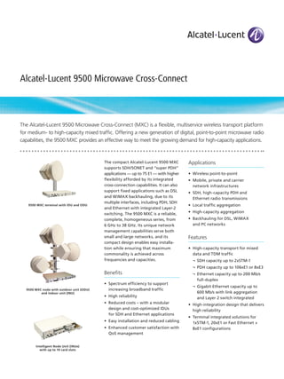
9500 MXC terminal with IDU and ODU • Local traffic aggregation
and Ethernet with integrated Layer-2
switching. The 9500 MXC is a reliable, • High-capacity aggregation
complete, homogeneous series, from • Backhauling for DSL, WiMAX
6 GHz to 38 GHz. Its unique network and PC networks
management capabilities serve both
small and large networks, and its Features
compact design enables easy installa-
tion while ensuring that maximum • High-capacity transport for mixed
commonality is achieved across data and TDM traffic
frequencies and capacities. ¬ SDH capacity up to 2xSTM-1
¬ PDH capacity up to 106xE1 or 8xE3
Benefits ¬ Ethernet capacity up to 200 Mb/s
full-duplex
• Spectrum efficiency to support
¬ Gigabit Ethernet capacity up to
9500 MXC node with outdoor unit (ODU) increasing broadband traffic
and indoor unit (INU) 600 Mb/s with link aggregation
• High reliability and Layer 2 switch integrated
• Reduced costs – with a modular • High-integration design that delivers
design and cost-optimized IDUs high reliability
for SDH and Ethernet applications
• Terminal integrated solutions for
• Easy installation and reduced cabling 1xSTM-1, 20xE1 or Fast Ethernet +
• Enhanced customer satisfaction with 8xE1 configurations
QoS management
Intelligent Node Unit (INUe)
with up to 10 card slots
2. • Node configuration and integrated Technical specifications Dimensions
cross-connection functionalities IDU and INU
¬ Flexible aggregate capacity • Height: 44.5 mm (1.75 in)
Configurations
sharing between E1s and Ethernet • Width: 480 mm (18.9 in)
• Unprotected
• Depth: 300 mm (11.8 in)
¬ Powerful embedded traffic • 1+1 hot-standby
INUe
routing with E1 cross-connect • 1+1 space diversity
• Height: 89 mm (3.50 in)
¬ Nodal capabilities supporting up • 1+1 frequency diversity
• Width: 480 mm (18.90 in)
to six radio paths (with INUe) • Co-channel cross-pol operation
(XPIC) • Depth: 300 mm (11.81 in)
• Universal ODU (16, 32, 64, 128 and ODU
• Repeater with traffic add-drop
256 QAM; 64 Mb/s to 311 Mb/s) • Height: 284 mm (11.18 in)
• 3-, 4-, 5- and 6-way nodal
• Java™-based craft terminal configuration with traffic routing • Width: 284 mm (11.18 in)
• Full software configurable modulation • E1 and STM-1 line protection • Depth: 162 mm (6.38 in)
and capacity
System-level specifications Environmental
• Highly modular architecture
• Operating frequencies: 6, 7, 8, • IDU and INU: -5°C to +45°C
10.5, 11, 13, 15, 18, 23, 26, 28 • INUe: -50°C to +65°C
and 38 GHz
• ODU: -33°C to +55°C
• Modulation options: QPSK, 16,
32, 64, 128 and 256 QAM
Standards compliance
• Capacity ranges: 32, 40, 48, 52,
64, 75, 93 and 106 E1; 1, 2, 3, 4, • EMC: EN 301 489
5, 6, 7 and 8 E3; 1 and 2 STM-1 • Operation
¬ ODUs: ETS 300 019, Class 4.1
Power requirements ¬ IDUs: ETS 300 019, Class 3.2
• Input voltage range: • Storage: ETS 300 019, Class 1.2
-40 to -60 V DC
• Transportation: ETS 300 019,
• Power consumption Class 2.3
¬ IDU: 10 W • Radio frequency: EN 302 217
¬ INU and INUe: dependent on • Safety: EN 60950
cards installed:
• Water ingress (ODUs)
- Radio Access Card: 6 W IEC 60529 (IPX6)
- Digital Access Card: 3 W
- Node Control Card: 4 W
- Node Protection Card: 4 W
- Fan Unit: 2 W
¬ ODU: 50 W maximum
2 Alcatel-Lucent 9500 Microwave Cross-Connect | Data Sheet
3. Table 1. Technical summary (Part 1)
Modulation scheme QPSK, 16 QAM, 32 QAM, 64 QAM, 128 QAM, 256 QAM (software selectable)
Capacity PDH ETSI: 20,40, 52, 64, 75, 93 and 106 E1
SDH: STM-1, 2xSTM-1 single-carrier at 56 MHz, 2xSTM-1 XPIC
LAN: 4x 10/100 BASE-T(X), 1000 BASE-LX, 3x1000 BASE-T
Channel spacing (MHz) and
modulation options 7 (5 E1), 14 (10 E1), 28 (20 E1) for QPSK
7 (10 E1), 14 (20 E1), 28 (3 2E1), 28(40 E1), 56 (64 E1), 56 (75 E1), 56 (STM-1) for 16 QAM
14 (27 E1), 28 (52 E1) for 32 QAM
7 (16 E1), 14 (32 E1), 28 (64 E1), 56 (100 E1), 40 (STM-1) for 64 QAM
28 (75 E1), 28 (STM-1), 56 (2xSTM-1) for 128 QAM
28 (93 E1) for 256 QAM
Configurations 1+0, 1+1 HSB/SD/FD, 1+1 HSB XP, 2+0
ODU300hp RF SPECIFICATIONS L6/U6 GHz 7.0 GHz 8.0 GHz 10.5 GHz 11.0 GHz
SYSTEM
Frequency range, GHz 5.925 to 6.425 7.125 to 7.9 7.725 to 8.5 10.0 to 10.68 10.7 to 11.7
6.425 to 7.11
T-R spacings supported, MHz 252.04 154, 161, 168, 119, 126, 91, 230, 490, 530
340 196, 245 151.614, 143.5, 350
266, 311.32
Maximum tuning range 56 56 140 165 165
(dependent upon T-R
spacing), MHz
TRANSMITTER SPECIFICATIONS
Power output, nominal (dBm) QPSK 28.5 28.5 28.5 26.0 24.0
16 QAM 26.5 26.5 26.5 24.0 22.0
32 QAM 26.0 26.0 26.0 23.5 21.5
64 QAM [2] 25.5 25.5 25.5 23.0 21.0
128 QAM 24.5 24.5 24.5 22.0 20.0
256 QAM 22.5 22.5 22.5 20.0 18.0
RECEIVER SPECIFICATIONS [1] [3] CAPACITY CHANNEL MODULATION
Threshold at 10-6 BER (dBm) 5xE1 7.0 MHz QPSK -92.0 -92.0 -92.0 -91.5 -91.5
10xE1 13.75/14.0 MHz QPSK -89.0 -89.0 -89.0 -88.5 -89.0
20xE1 27.5/28.0 MHz QPSK -86.0 -86.0 -86.0 -85.5 -86.0
10xE1 7.0 MHz 16 QAM -85.5 -85.5 -85.5 -85.0 -85.0
20xE1 13.75/14.0 MHz 16 QAM -82.5 -82.5 -82.5 -82.0 -82.0
27xE1 13.75/14.0 MHz 32 QAM -78.5 -78.5 -78.5 -78.0 -78.0
32xE1 27.5/28.0 MHz 16 QAM -80.5 -80.5 -80.5 -80.0 -80.0
32xE1 13.75/14.0 MHz 64 QAM -75.5 -75.5 -75.5 -75.0 -75.5
40xE1 27.5/28.0 MHz 16 QAM -79.5 -79.5 -79.5 -79.0 -79.0
52xE1 27.5/28.0 MHz 32 QAM -76.0 -76.0 -76.0 -75.5 -75.5
64xE1 27.5/28.0 MHz 64 QAM -72.5 -72.5 -72.5 -72.0 -72.5
RAC 3X/40 64xE1 27.5/28.0 MHz 64 QAM -74.0 -74.0 -74.0 -73.5 -73.5
75xE1, 1xSTM1 55.0/56.0 MHz 16 QAM -76.5 -76.5 -76.5
75xE1, 1xSTM1 40.0 MHz 64 QAM -74.0 -73.5 -74.0
75xE1, 1xSTM1 27.5/28.0 MHz 128 QAM -69.5 -69.5 -69.5 -69.0 -69.5
RAC 3X/40 75xE1, 1xSTM1 27.5/28.0 MHz 128 QAM -71.0 -71.0 -71.0 -70.5 -70.5
93xE1 27.5/28.0 MHz 256 QAM -65.5 -65.5 -65.5 -65.0 -65.0
106xE1 55.0/56.0 MHz 64 QAM
8xE3, 2xSTM1 55.0/56.0 MHz 128 QAM -66.0 -66.0 -66.0
All specifications are referenced to the ODU antenna flange, and are typical values unless otherwise stated, and are subject to change without notice.
For guaranteed values (over time and operational range) subtract 2 dB from power output, add 2dB to threshold values, and subtract 4 dB from system gain values.
[1] System gain and receiver threshold values are for BER = 10 -6. Values for BER = 10 -3 are improved by 1 dB.
[2] Transmit power output values for 64xE1 64 QAM will be reduced by 1 dB from the 64QAM value indicated.
[3] Receiver threshold values are for BER=10 -6. Values for BER = 10 -3 are improved by 1 dB.
Alcatel-Lucent 9500 Microwave Cross-Connect | Data Sheet 3
4. Table 1. Technical summary (Part 2)
Modulation scheme QPSK, 16 QAM, 32 QAM, 64 QAM, 128 QAM, 256 QAM (software selectable)
Capacity PDH ETSI: 20,40, 52, 64, 75, 93 and 106 E1
SDH: STM-1, 2xSTM-1 single-carrier at 56 MHz, 2xSTM-1 XPIC
LAN: 4x 10/100 BASE-T(X), 1000 BASE-LX, 3x1000 BASE-T
Channel spacing (MHz) 7 (5 E1), 14 (10 E1), 28 (20 E1) for QPSK
and modulation options 7 (10 E1), 14 (20 E1), 28 (3 2E1), 28(40 E1), 56 (64 E1), 56 (75 E1), 56 (STM-1) for 16 QAM
14 (27 E1), 28 (52 E1) for 32 QAM
7 (16 E1), 14 (32 E1), 28 (64 E1), 56 (100 E1), 40 (STM-1) for 64 QAM
28 (75 E1), 28 (STM-1), 56 (2xSTM-1) for 128 QAM
28 (93 E1) for 256 QAM
Configurations 1+0, 1+1 HSB/SD/FD, 1+1 HSB XP, 2+0
ODU300hp RF 13.0 GHz 15.0 GHz 18.0 GHz 23.0 GHz 26.0 GHz 28.0 GHz 32.0 GHz 38.0 GHz
SPECIFICATIONS
SYSTEM
Frequency range, GHz 12.75 to 14.4 to 17.7 to 21.2 to 24.52 to 27.5 to 31.8 to 37.0 to
13.25 15.35 19.7 23.632 26.483 29.5 33.4 39.46
T-R spacings supported, 266 315, 420, 1010, 1008, 1008 1008 812 1260
MHz 490, 644, 1092.5 1200,
728 1232
Maximum tuning range 84 245 380 370 360 360 370 340
(dependent upon T-R
spacing), MHz
TRANSMITTER
SPECIFICATIONS
Power output, nominal
(dBm) 23.0 22.0 19.5 19.5 15.5 15.0 18.0 17.5
21.0 20.0 17.5 17.5 13.5 13.0 16.0 15.5
20.5 19.5 17.0 17.0 13.0 12.5 15.5 15.0
20.0 19.0 16.5 16.5 12.5 12.0 15.0 14.5
19.0 18.0 15.5 15.5 11.5 11.0 14.0 13.5
17.0 16.0 13.5 13.5 9.5 9.0 12.0 11.5
RECEIVER SPECIFICATIONS CAPACITY CHANNEL MODU
[1] [3] LATION
Threshold at 10-6 BER
(dBm) 5xE1 7.0 MHz QPSK -91.5 -91.5 -91.0 -91.0 -90.0 -89.0 -89.0 -88.5
10xE1 13.75/14.0 MHz QPSK -89.0 -88.5 -88.5 -88.0 -87.0 -86.5 -86.0 -86.0
20xE1 27.5/28.0 MHz QPSK -86.0 -85.5 -85.5 -85.0 -84.0 -83.5 -83.0 -83.0
10xE1 7.0 MHz 16 QAM -85.0 -85.0 -84.5 -84.5 -83.5 -82.5 -82.0 -82.0
20xE1 13.75/14.0 MHz 16 QAM -82.0 -82.0 -81.5 -81.5 -80.5 -79.5 -79.0 -79.0
27xE1 13.75/14.0 MHz 32 QAM -78.0 -78.0 -77.5 -77.5 -76.5 -75.5 -75.0 -75.0
32xE1 27.5/28.0 MHz 16 QAM -80.0 -80.0 -79.5 -79.5 -78.5 -77.5 -77.0 -77.0
32xE1 13.75/14.0 MHz 64 QAM -75.5 -75.0 -75.0 -74.5 -73.5 -72.5 -72.0 -72.0
40xE1 27.5/28.0 MHz 16 QAM -79.0 -79.0 -78.5 -78.5 -77.5 -76.5 -76.0 -76.0
52xE1 27.5/28.0 MHz 32 QAM -75.5 -75.5 -75.0 -75.0 -74.0 -73.0 -72.5 -72.5
64xE1 27.5/28.0 MHz 64 QAM -72.5 -72.0 -72.0 -71.5 -70.5 -69.5 -69.0 -69.0
RAC 3X/40 64xE1 27.5/28.0 MHz 64 QAM -73.5 -73.5 -73.0 -73.0 -72.0 -70.5 -70.5 -70.0
75xE1, 1xSTM1 55.0/56.0 MHz 16 QAM -76.0 -76.0 -76.0 -75.5 -74.5 -73.5 -73.0 -73.0
75xE1, 1xSTM1 40.0 MHz 64 QAM
75xE1, 1xSTM1 27.5/28.0 MHz 128 QAM -69.5 -69.0 -69.0 -68.5 -67.5 -66.0 -65.5 -65.5
RAC 3X/40 75xE1, 1xSTM1 27.5/28.0 MHz 128 QAM -70.5 -70.5 -70.0 -70.0 -69.0 -67.0 -67.0 -66.5
93xE1 27.5/28.0 MHz 256 QAM -65.0 -65.0 -64.5 -64.5 -62.5 -61.5 -61.5 -60.5
106xE1 55.0/56.0 MHz 64 QAM -71.5 -71.0 -69.5 -69.0 -68.5 -68.5
8xE3, 2xSTM1 55.0/56.0 MHz 128 QAM -66.0 -65.5 -65.5 -65.0 -64.0 -62.5 -62.0 -62.0
All specifications are referenced to the ODU antenna flange, and are typical values unless otherwise stated, and are subject to change without notice.
For guaranteed values (over time and operational range) subtract 2 dB from power output, add 2dB to threshold values, and subtract 4 dB from system gain values.
[1] System gain and receiver threshold values are for BER = 10 -6. Values for BER = 10 -3 are improved by 1 dB.
[2] Transmit power output values for 64xE1 64 QAM will be reduced by 1 dB from the 64QAM value indicated.
[3] Receiver threshold values are for BER=10 -6. Values for BER = 10 -3 are improved by 1 dB.
4 Alcatel-Lucent 9500 Microwave Cross-Connect | Data Sheet