More than Just Lines on a Map: Best Practices for U.S Bike Routes
Fluo Light Manager Install
1. Single Pole (One Loca/on) or 3 Way (Mul/ Loca/on) Fluorescent Light Manager
120 VAC, 60 Hz, 300 W
Installa/on Instruc/ons
WARNINGS:
CAUTIONS:
• To be installed and used in accordance with appropriate electrical codes and regula/ons.
• Disconnect power at circuit breaker or fuse when servicing fixture.
• If you are unsure about any part of these instruc/ons, consult a qualified electrician.
• During normal opera/on, dimmer may feel warm to the touch.
• To avoid overhea/ng and possible damage to this device and other equipment, use only as instructed.
• Only use this device with cooper or copper clad wire.
• Use only one (1) dimmer per ligh/ng load and do not exceed a total load of 300 WaSs / 150 WaSs if using CFL’s.
Tools needed to install your FLM:
Phillips Screwdriver
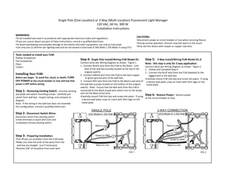
Step 4: Single Pole Install/Wiring FLM Model 01: Step 5: 3 Way Install/Wiring FLM Model 01.3:
Flat Screwdriver
Connect wires per Wiring Diagram as shown. Figure 1 Note: this step is only for 3 way applicaPon
Pliers
1. Connect BLACK wire from the FLM to the Black – Line Connect wires per Wiring Diagram as shown. Figure 2
CuSers
wire of the wall box (usually located at the top of the 1. Follow and Complete Step 4:
original switch). 2. Connect the BLUE wire from the FLM (labeled) to the
Installing Your FLM: 2. Connect GREEN wire from the FLM to the bare copper tagged wire in the wall box.
Before you begin: To avoid fire, shock, or death; TURN or green ground wire of the wall box. • Carefully mount FLM into box and screw into place. If using
OFF POWER at the circuit breaker or fuse and test that 3. Connect RED wire from the FLM to the Black‐Load wire of a decora wall plate, snap on insert with iDim logo on the
power is OFF before wiring. the wall box (usually located on the boSom of the original metal plate.
switch). Note: Ensure that the Red wire from the FLM is
Step 1: Removing ExisPng Switch: Unscrew exis/ng connected to the Black (Load) wire which runs to the lamps
and not the Black (Line) wire.
Step 6: Restore Power: Restore power
wall plate and switch moun/ng screws. Carefully pull
• Carefully mount FLM into box and screw into place. If using
switch from wall box. Inspect wiring, and compare to at the circuit breaker or fuse.
a decora wall plate, snap on insert with iDim logo on the
diagram.
metal plate.
Note: If the wiring in the wall box does not resemble
this configura/on, consult a qualified electrician.
Step 2: Disconnect Switch Wires:
Disconnect wires from exis/ng switch
screw terminals or quick wire slots and
completely remove exis/ng switch.
Step 3: Preparing InstallaPon:
• Pull off pre‐cut insula/on from the FLM leads.
• Make sure that the ends of the wires from the
wall box are straight. (cut if necessary)
• Remove 5/8” of insula/on from each wire.
2. OperaPon:
Reference Guide: TroubleshooPng:
ON: Turn the FLM‐01 on by pushing
1. Power Switch: Push “ON” / Push “OFF” Lights Flickering:
the power switch (switch 1). The load will • In case of non‐dimmable CFL bulb(s) flickering during
AC Power Switch
start slowly increasing in brightness (10‐12 decrease or increase in light intensity: reconnect Green
2. Light Intensity Switch: Push light
seconds) and then returns to the last wire from the FLM to the White/Neutral wire, if available,
intensity switch to adjust light intensity seing stored in memory ajer 60 second of the wall box. If flickering does not stop, replace the
level delay built in sojware. non‐dimmable CFL bulb with a different brand.
4. PotenPometer: Rotate Poten/ometer • Lamp has a bad connec/on.
to preset minimum light intensity Changing the Intensity: • Wires are not secured with wire connectors.
level. • Pushing the light intensity switch (switch 2) Light Does Not Turn On:
Note: 50% maximum reduc/on for changes the light intensity. • The fuse or circuit breaker is tripped.
• The switch can be pushed in 1 – 2 second
most CFL’s. • Lamp is burned out.
intervals up to 6 /mes. • Lamp Neutral connec/on is not wired properly.
• Each press decreases the light intensity. • FLM power buSon needs to be centered in the switch
• The 6th press will set the light intensity to opening to allow for full movement.
the minimum/lowest seing.
• To increase the light intensity, press 6 /mes • Disclaimer: CFL bulb manufacturers do not recommend
from the lowest seing. Each step will increase the dimming non‐dimmable CFL bulbs; however, the FLM models
light intensity. 01 and 01.3 are capable of dimming non‐dimmable CFL’s.
• Once light intensity preferences are set, the light • It is recommended to use CFL bulbs with all the same waSage
intensity switch is set so you may push & hold and the any one FLM to ensure equal dimming.
light intensity will decrease. Push & hold 1 second and • As with any CFL bulb, prolonged or permanent use at the lowest
the light intensity will increase to full brightness. light level may shorten the life of the bulb.
• It is recommended not to mix CFL bulbs with incandescent,
DIM: or halogen on any one FLM.
• Use the poten/ometer (switch 3) to set the
total decrease in intensity.
• The default seing will handle most lights;
however, due to different setups and
preferences, it may need to be re‐adjusted.
• Adjustments will be stored in memory once set.
When you turn lights off and on again, the lights
will . automa/cally go to the pre‐set level ajer 60
second
delay.
• If bulbs flicker, the FLM is set too low and
must be set to a higher level.
OFF: Turn the FLM‐01 off by pushing the power
switch again. The FLM must be allowed 10 – 12
seconds ajer shut down to discharge prior to
being turned on again.
Note: The FLM has AC Power Failure Memory that will
automa/cally return lights to last set level.