
Recommended
Recommended
More Related Content
Similar to Led display user manual
Similar to Led display user manual (20)
Recently uploaded
Recently uploaded (20)
Led display user manual
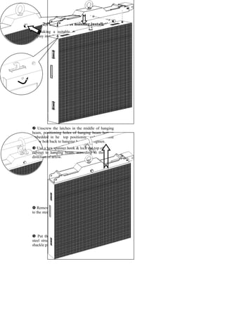
- 1. (2)Procedures of hoisting installation Making a suitable steel structure for LED display installation. Unscrew the latches in the middle of hanging beam, positioning holes of hanging beam bottom embedded in he top positioning column, while screw bolt back to hanging beam then tighten. Put the cabinets with hanging beam on the steel structure, make the rings in the U-shaped shackle pin through rings installed. Removed the U-shaped shackle pin and hung on to the steel structure. Use a hex spanner hook & lock the top of cabinet to hanging beam, according to the direction of arrow.
- 2. Hanging beam on the top of two cabinets installed and fixed by M10*20mm SHCS, U- shaped connector of hanging beam. Install the second cabinet in the same way, hang on a steel frame, and make two cabinets try to close up. Accordance with the direction of arrow, use hex spanner to open the hook lock of the side of cabinet and catch the second cabinet. Fixed all the cabinets by M10*25mm SHCS, two-hole and four-hole square connectors. U-shape connector for hanging beam M10*20mm SHCS
- 3. Warning: Please be sure to carefully lay LED to avoid strongly striking it. Take necessary safety steps in the course of installation to avoid causing personal and property damages. Maximum height of the vertical installation is not more than 15pcs cabinets height. Hoisting installation maximum height not more than 10pcs cabinets height. After Installed the cabinets on the top row, then connect the following cabinets with hook lock, connector and fixed.
- 4. V. LED display screen system installation Shenzhen Zhongyi Optoelectronics Co.ltd Email:sales@szledzy.com Mob: +86 13544082677 [I] Card type part of control system (1) Sending card——installed in the host computer, external sending box or video processor for the use of conveying data to LED display screen. (2) Receiving card——installed in LED cabinets, make LED display image by receiving data from sending card. (3) Keyset——installed on receiving card, distribute data to every module of LED display screen. LINSN sending card DBSTAR sending card Nova sending cardLINSN receiving card DBSTAR receiving card Nova receiving card
- 6. (4) External sending card Power switch Power plug Display 16 level LED Display luminance Brilliance control button Sending card U interface Sending card D interface USB interface DVI interface Audio frequency interface Power (red), signal(green) indicator light LINSN external sending card DBSTAR external sending card Power switch Power plugSending card interface 2 Sending card interface 1 USB interface DVI interface Power switch Cascade output Cascade input Light-sensitive probe interface DVI interfacePower plug Sending card interface 1 Sending card interface 2 NOVA external sending card USB interface
- 7. [II] Wire rod part of control system [III] LED Display Screen System Installation (1) Sending card installation: install sending card as the following pictures after opening rear cover of computer host. Discrete graphics card PCI slot Insert sending card into PCI slot Fix sending card by screw Screwdriver Warning: Cut off power first before the following operating! DVI turning VGA line USB turning RS232 lineUSB line VGA line DVI line DVI line divided into two parts DVI line HDMI turning DVI line
- 8. (2) Connection of control system Connection schematic diagram of desktop computer internal sending card: Connection schematic diagram of laptop external sending card: HDMI turning DVI line USB line Network line LED display screen Laptop LINSN external sending card VGA or DVI line DVI line Network line Displayer Computer host USB line U D Audio frequency output Sending card Graphics card LED display screen