SlideShare a Scribd company logo
1 of 10
Download to read offline
Petroleum Production Engineering II
Year 4– Department of Petroleum Engineering
University of Baghdad
1
Dr. Dhifaf Jaafar Sadeq
1. Introduction to Production Engineering
1.1 Scope
The production system is a composite term describing the entire production process and
includes the principal components as follows:
1) The reservoir – its productive capacity and production characteristics.
2) The wellbore – the production interval, the sump and the fluids in the wellbore.
3) Production conduit – comprising the tubing and the tubing components.
4) Wellhead, Xmas Tree and Flow lines.
5) Treatment facilities.
From the above definition it can be seen that the responsibilities of Production Engineer cover
principally downhole aspects of the system but they also extend to some of the surface facilities and
treatment capabilities.
Production Engineer is so defined as to be a blend of engineering and chemistry. The role of the
Production Engineer is one of the achieving optimum performance from a production system and to
achieve this the engineers must understand fully the chemical and physical characteristics of the fluids
which he or she seeks to produce and also the engineering systems which he or she will utilize to control
the production/injection of fluids, efficiently and safely.
The main topics covered by a production engineer can be identified as:
1) Production Engineering:
o Fluid flow.
o Reservoir dynamics.
o Equipment design, installation, operation, and fault diagnosis.
2) Chemistry
o The fluids – produced, injected and treatment fluids.
o The rock – mineral, mineralogy, physical chemical properties, and rock response.
Petroleum Production Engineering II
Year 4– Department of Petroleum Engineering
University of Baghdad
2
Dr. Dhifaf Jaafar Sadeq
1.2 Primary reservoir energy
A reservoir will produce naturally as a consequence of the fluid which it contains, existing at high
pressure within the reservoir rock that is in state of compaction. Thus, the reservoir as such contains an
enormous amount of energy in the form of compressive energy which can be utilized to allow fluid to
be produced from the reservoir, through expansion, into a well and then on to surface and finally into
treatment facilities.
The response of the reservoir to the pressure depletion process, which occurs during production, will
be dynamic and the fluid remaining in the reservoir will change both in terms of its volume, composition,
pressure and other rock and fluid properties. The manner in which the reservoir system respond to the
depletion process will be naturally governed by the drive mechanism inherent in the reservoir. The long-
term production capacity of the reservoir will be dependent on the dominant drive mechanism present
within the reservoir. The depletion effects can be supplemented by the injection of a fluid, either water
or gas back into the reservoir depending on the hydrocarbon fluid properties.
Once the reservoir delivers fluid to the wellbore, sufficient pressure energy needs to exist to lift the fluid
to surface if the well is to operate on natural flow. In the event that insufficient energy exist to allow
production to occur at an economic rate, the well may require assistance by the application of an
artificial lift technique.
The production of a reservoir fluid under its own energy is dependent on the reservoir pressure being
sufficient to counteract the hydrostatic head (from surface) generated by the fluids, the frictional
pressure drop generated by the flowing fluid in the production tubing and the minimum wellhead
pressure that will be required to feed the production separator. The removal of fluids from the reservoir
will cause the pressure in the reservoir to drop and this loss of energy is compensated to a degree by
one or more of the following mechanisms:
1- Compacting of the reservoir rock matrix.
2- Expansion of the connate water.
3- Expansion of hydrocarbon phases present in the reservoir:
a- If the reservoir is above the bubble point, then expansion of oil until the bubble point is
reached.
b- If the reservoir is below the bubble point, then the expansion of oil and gas phases.
c- Expansion of any overlying gas cap.
Petroleum Production Engineering II
Year 4– Department of Petroleum Engineering
University of Baghdad
3
Dr. Dhifaf Jaafar Sadeq
d- Expansion of an underlying aquifer resulting in water influxing into the portion of the
reservoir that are vacated by the produced fluids. The strength of the aquifer will determine
the pressure support provided.
In most cases, as oil produced, the system cannot maintain its pressure and the overall pressure in the
reservoir will decline. The pressure stored in the reservoir in the form of compressed fluid and rock
presented the significant natural energy available for the application of fluids from reservoir to surface.
The mechanism by which a reservoir produces its fluids and compensates for the production is termed
the reservoir drive mechanism and refers to the method by which the reservoir provides the energy
during production. There are a number of drive mechanism (listed below) and the reservoir may be
under the influence of one or more of these mechanisms simultaneously.
(a) Solution Gas Drive
If oil is found initially in the reservoir above its bubble point, the loss of reservoir energy due to the
removal of the produced oil will be compensated for by an expansion of the oil left in place within
the reservoir until the bubble point is reached. This will be necessity lead to a reduction in pressure
and eventually the pressure within the reservoir will drop below the bubble point. Gas will then come
out of the solution and any subsequence production of the fluid will lead to an expansion of both oil
and gas phases within the reservoir. A reservoir found above its bubble point is referred to as
saturated reservoir as no more gas can be absorbed by the oil at that pressure.
The fluid’s producing gasoil ratio rises quickly as the bubble link up and begin to flow and may
increase to as ten times its initial value. Oil production rates fall quickly once the gas/oil ratio begins
to rise. Wells must be placed on artificial lift early in their life. Initially, little or no water is produced.
As a reservoir pressure continues to fall, the cumulative gas production eventually reaches a point
where a significant portion of solution gas liberated in the reservoir is produced to surface and oil
production diminishes.
(b) Gas Cap Expansion Drive
If a reservoir is found at its bubble point, it may have a gas cap containing a free gas column above
the oil leg. Drive energy in a gas cap drive reservoir is provided by the expansion of the initial gas cap
combined with the energy provided by the solution gas released from the oil. Reservoir pressure
drops more gradually than in a solution gas drive due to the pressure support provided by the gas
cap.
Petroleum Production Engineering II
Year 4– Department of Petroleum Engineering
University of Baghdad
4
Dr. Dhifaf Jaafar Sadeq
The field gasoil ratio rises continuously as the expanding gas cap reaches the wells situated higher
up on the structure
(c) Water Drive
Drive energy in a water drive reservoir is provided primarily by water influx from an aquifer in
pressure communication with the oil zone. In strong water drives, reservoir pressures are
maintained, and the field gas/oil ratio remains low as water moves in to place the produced fluids.
In a water drive reservoir, the oil zone in a communication with an aquifer providing the bulk of
reservoir’s drive energy. As oil is produced, the water in the aquifer expands and moves into the
reservoir, displacing oil. Depending on the aquifer’s strength, additional energy may be provided
by solution gas expansion of the reservoir rock and its associated water.
Recoveries from this type of reservoir will be the highest if the mobility of the oil is greater than
that of the water.
(d) Combination drive
Drive energy in a combination drive reservoir is provided by a combination of two or more drive
mechanism. The production trends reflect the characteristic of the dominant drive mwchanisim,
which may change with time. The recovery may be high or low, depending on which drive
mechanisms dominate.
Figure (1.1) illistrates the reservoir performance for the tree majour primary drive mechanism
Petroleum Production Engineering II
Year 4– Department of Petroleum Engineering
University of Baghdad
5
Dr. Dhifaf Jaafar Sadeq
1.3 Well productivity
An oil and gas reservoir contains highly compressible hydrocarbon fluids at an elevated pressure
and temperature and such as, the fluid stores up within itself considerable energy of compression.
The efficient production of fluids from a reservoir requires the effective dissipation of this energy
through the production system. Optimum utilization of this energy is an essential part of the
successful completion.
The productivity of the system is dependent on the pressure loss, which occurs in several areas of
the flow system namely:
• The reservoir
• The wellbore
• The tubing
• The choke
• The flow line
• The separator
The optimum distribution of energy between these various areas has a major bearing on the
production effectiveness of well completion the selection of the appropriate completion string is
fit for the purpose components which will control the cost effectiveness.
The optimum distribution of energy between these various has a major bearing on the production
effectiveness of well completion. The selection of the appropriate completion string is fit for the
purpose components which will control the cost effectiveness.
The pressure drop, which occurs across the reservoir, is defined as the inflow performance
relationship or IPR. The pressure drop in the tubing and wellbore, post perforation, is that which
occurs in lifting the fluid from the reservoir to the surface and it known as the vertical lift
performance (VLP), or the tubing performance relationship (TPR). This is a frictional pressure drop
caused by the flow of fluids through the casing and production tubing to the well head. In addition
to overcoming the frictional pressure drop it is also necessary to have sufficient energy in the
reservoir fluid to overcome the hydrostatic head required for the fluid to reach the surface from
reservoir depth and to maintain the stipulated wellhead pressure which is required to feed the
reservoir fluids into the production phase separator at its optimum operation pressure.
Petroleum Production Engineering II
Year 4– Department of Petroleum Engineering
University of Baghdad
6
Dr. Dhifaf Jaafar Sadeq
The pressure drop across the reservoir, the tubing and in fact the choke is rate dependent and
these relationships therefore define the means by which we can optimize the production of the
fluid from the reservoir.
In some cases, these will impose significant limitations on the extent to which we can utilize and
optimize the dissipation of this energy. These are discussed below:
(1) Limited reservoir Pressure – in cases where the reservoir pressure is limited, it may not be
feasible to achieve a significant and economic production rate from the well. In such cases it
may be necessary to either assist in maintaining reservoir pressure or arrest the production
decline by the use of gas or water injection for re-pressurization. Alternatively, the use artificial
lift technique to offset some of the vertical lift pressure requirements and thus increases the
production capacity of the system may be implemented. Pressure drop across the wellbore can
be reduced substantially by having a horizontal section in the wellbore. This basically increases
the length of formation available for production, hence increasing the productivity index, PI, of
the well.
(2) Minimum Surface Pressure – on arrival at the surface, the hydrocarbon fluids re fed down a
pipeline through the choke and a production manifold to the production separator, where
phase separation is allowed to take place. The production rates of oil, gas and water are
measured here prior to the separate phases, oil, gas and water, being sent to various treatment
facilities for further processing. To be able to allow the fluids to be driven through the initial
separation process and in fact to provide some of the energy required for the process itself and
to maximize the production rate, it will be necessary to have the minimum possible wellhead
pressure that will be greater than the sum of the frictional pressure drop between the wellhead
and the separator and the operating pressure of the separator itself (normally 100 to 200 psig).
1.4 The composite production system
The composite production system is comprised of the production casing, the subsurface well
completion, the wellhead, the choke and the flowlines to the production separator, the
production separation process itself and the facilities used for transferring the produced fluids
to their intended destinations.
Petroleum Production Engineering II
Year 4– Department of Petroleum Engineering
University of Baghdad
7
Dr. Dhifaf Jaafar Sadeq
1.4.1 General description
The energy stored within the reservoir is available to cause the flid to flow from the
reservoir to the wellbore and then to the surface. The design of a production system that
efficiently uses this available energy to maximize the production from the reservoir to the
wellhead is fundamental to efficient well completion design and the responsibility rests with
the production technologist.
During the production of oil from the reservoir to a storage tank, the oil has to flow through
a variety of restrictions that will consume some of the energy stored within the compressed
fluids and controlled by their pressure and temperature. The combined system of the
reservoir, the wellbore and the surface treatment facilities is generally referred to as the
composite production system ( Figure (1.2))
Figure (1.2) Composite Production System
Petroleum Production Engineering II
Year 4– Department of Petroleum Engineering
University of Baghdad
8
Dr. Dhifaf Jaafar Sadeq
1.5.2 Utilization of Reservoir Pressure
In the development of a hydrocarbon reservoir, the energy stored up within the compressed state of
the reservoir flids has to, in the majority of cases, overcome the total pressure loss in the producing
system. Based upon a fixed operating pressure for the separator, we can formulate the pressure loss
distribution as follows:
𝑃𝑅𝐸𝑆 = ∆𝑃𝑅𝐸𝑆 + ∆𝑃𝑊𝐵 + ∆𝑃𝑃𝑇 + ∆𝑃𝑆𝑈𝑅𝐹 + ∆𝑃𝐶𝐻𝑂𝐾𝐸 + 𝑃𝑆𝐸𝑃 (1.1)
Where,
𝑃𝑅𝐸𝑆 is the initial or average pressure within the well drainage area in the reservoir.
∆𝑃𝑅𝐸𝑆 is the pressure loss caused by the flow of fluid within the reservoir to the wellbore.
∆𝑃𝑊𝐵 is the total pressure loss generated by the design of the fluid entry into the wellbore.
∆𝑃𝑃𝑇 is the pressure loss caused by fluid flowing up the production tubing string.
∆𝑃𝑆𝑈𝑅𝐹 is the pressure loss generated in the Xmas tree, production manifold and surface flowlines.
∆𝑃𝐶𝐻𝑂𝐾𝐸 is the pressure loss across the choke.
𝑃𝑆𝐸𝑃 is the required operating pressure for the separator.
The pressure drop required to bring the fluids from the wellbore to the wellhead can be calculated
from the following equation:
∆𝑃𝑅𝐸𝑆 = ∆𝑃𝐹 + ∆𝑃𝐻 (1.2)
Where,
∆𝑃𝐹 is the frictional pressure drop in the production tubing which is a function of the fluid velocity.
∆𝑃𝐻 is the hydrostatic head between the wellbore and the wellhead which is dependent on the density
of the fluids present in the tubing, the vertical distance between the wellbore and the wellhead and
gravity.
∆𝑃𝐻= ρgh
Equation (1.1) can be rearranged to give,
Petroleum Production Engineering II
Year 4– Department of Petroleum Engineering
University of Baghdad
9
Dr. Dhifaf Jaafar Sadeq
(𝑃𝑅𝐸𝑆 − 𝑃𝑆𝐸𝑃) = ∆𝑃𝑅𝐸𝑆 + ∆𝑃𝑊𝐵 + ∆𝑃𝑃𝑇 + ∆𝑃𝑆𝑈𝑅𝐹 + ∆𝑃𝐶𝐻𝑂𝐾𝐸 (1.3)
Where, (𝑃𝑅𝐸𝑆 − 𝑃𝑆𝐸𝑃) is pressure drop available for the production system and hence will determine
the rate at which the fluids can be produced to the surface.
All the pressure drop terms in equation (1.3) are rate dependent and hence the total system pressure
drop can be calculated as:
∆𝑃𝑇𝑂𝑇𝐴𝐿 = [∆𝑃𝑅𝐸𝑆 + ∆𝑃𝑊𝐵 + ∆𝑃𝑃𝑇 + ∆𝑃𝑆𝑈𝑅𝐹 + ∆𝑃𝐶𝐻𝑂𝐾𝐸 + 𝑃𝑆𝐸𝑃]𝑄 (1.4)
Thus, each of pressure drops can be minimized either individually or collectively to give the maximum
production rate for the available pressure drop. This is known as the production system optimization.
The following text introduced the techniques normally used to minimize these pressure drops to
provide a maximum potential production rate.
To reduce the pressure loss due to flow in the reservoir it is necessary to reduce the resistance to flow.
This can be accomplished either by reducing the formation rock resistance, e.g., increasing the
permeability by acidization or fracturing or by reducing the resistance to flow due to the fluid
properties, e.g. viscosity by utilizing thermal recovery techniques. These alternatives are normally too
costly to be readily applicable expect in specific situations, e.g., chalk reservoirs or with very heavy
crude oil reservoirs and may involve considerable technical risk.
The pressure loss due to the bottom hole completion method has to be specified as part of completion
design and as such is a major area for production optimization. It is likely that detailed consideration
given to some aspects in this area sch as perforation shot density and length of perforated interval
could be very beneficial to maximizing the production capacity of the system. Consideration must also
be given to the possible use of a horizontal well instead of vertical or deviated well. In some cases,
multi-lateral wells may be looked at.
Again, as with the bottom hole completion pressure loss, the vertical lift pressure loss in the
production tubing is a major area for optimization, as not only does the engineer have to specify the
length and diameters of all sections of the tubing string but also all the specific completion
components used in the string. Careful design in this area should provide significant productive
capacity.
The surface flowline pressure loss is relatively less important in that it is easily controlled even after
the event. The diameter of the flowlines can be increased to compensate for the number of bends and
Petroleum Production Engineering II
Year 4– Department of Petroleum Engineering
University of Baghdad
10
Dr. Dhifaf Jaafar Sadeq
valves used in the system. Also the length of the flowline can be shortened through innovative facilities
design of the surface production facilities and layout. Even if mistakes were made during the initial
design, facilities can be upgraded without having to outlay too much capital.
Little flexibility exists to minimize choke size as it is required to give a specific pressure drop for known
flowrate to provide stability to the production separator.
1.5 Supplementary Reservoir Energy
The increase in production rate could attained by supplementing the natural reservoir energy through
either:
1- Increasing the reservoir pressure.
Or
2- Providing more energy for the vertical lift process.

More Related Content

What's hot

Petroleum reservoir performance overview
Petroleum reservoir performance overviewPetroleum reservoir performance overview
Petroleum reservoir performance overviewAndi Anriansyah
 
Enhanced Oil Recovery
Enhanced Oil RecoveryEnhanced Oil Recovery
Enhanced Oil Recoverygrantbearss
 
Subsea completion and control system
Subsea completion and control systemSubsea completion and control system
Subsea completion and control systemAmit Nitharwal
 
Miscellaneous Hydraulic Machines
Miscellaneous Hydraulic MachinesMiscellaneous Hydraulic Machines
Miscellaneous Hydraulic MachinesMohdAreebQureshi
 
Improving Oil Recovery In Fractured Reservoirs (Eor)
Improving Oil Recovery In Fractured Reservoirs (Eor)Improving Oil Recovery In Fractured Reservoirs (Eor)
Improving Oil Recovery In Fractured Reservoirs (Eor)Bakhtiar Mahmood
 
Manifold design, verification,_and_validation
Manifold design, verification,_and_validationManifold design, verification,_and_validation
Manifold design, verification,_and_validationjpegd
 
Hydraulicturbine 1
Hydraulicturbine 1Hydraulicturbine 1
Hydraulicturbine 1Mood Naik
 
Hydraulicturbine 1
Hydraulicturbine 1Hydraulicturbine 1
Hydraulicturbine 1Mood Naik
 
Subsea689_FinalSubmission_Ashwin_Kim_Thomas
Subsea689_FinalSubmission_Ashwin_Kim_ThomasSubsea689_FinalSubmission_Ashwin_Kim_Thomas
Subsea689_FinalSubmission_Ashwin_Kim_ThomasAshwin Gadgil
 
Basic Civil And Mechanical Engineering Question Bank
Basic Civil And Mechanical Engineering Question BankBasic Civil And Mechanical Engineering Question Bank
Basic Civil And Mechanical Engineering Question BankSanthosh Kumar
 
Conference dschang school_of_sci_&_tech_15-01-18
Conference dschang school_of_sci_&_tech_15-01-18Conference dschang school_of_sci_&_tech_15-01-18
Conference dschang school_of_sci_&_tech_15-01-18Université de Dschang
 
Jet engine aetd (2017-18)odd
Jet engine aetd (2017-18)oddJet engine aetd (2017-18)odd
Jet engine aetd (2017-18)oddDeepanBooramurthy
 
experimental analysis on francis turbine & to find out the power
experimental analysis on francis turbine & to find out the powerexperimental analysis on francis turbine & to find out the power
experimental analysis on francis turbine & to find out the powerNEERAJKUMAR1898
 

What's hot (19)

Petroleum reservoir performance overview
Petroleum reservoir performance overviewPetroleum reservoir performance overview
Petroleum reservoir performance overview
 
Oil & Gas Engineering
Oil & Gas EngineeringOil & Gas Engineering
Oil & Gas Engineering
 
Enhanced Oil Recovery
Enhanced Oil RecoveryEnhanced Oil Recovery
Enhanced Oil Recovery
 
Subsea completion and control system
Subsea completion and control systemSubsea completion and control system
Subsea completion and control system
 
Miscellaneous Hydraulic Machines
Miscellaneous Hydraulic MachinesMiscellaneous Hydraulic Machines
Miscellaneous Hydraulic Machines
 
Improving Oil Recovery In Fractured Reservoirs (Eor)
Improving Oil Recovery In Fractured Reservoirs (Eor)Improving Oil Recovery In Fractured Reservoirs (Eor)
Improving Oil Recovery In Fractured Reservoirs (Eor)
 
Manifold design, verification,_and_validation
Manifold design, verification,_and_validationManifold design, verification,_and_validation
Manifold design, verification,_and_validation
 
Hydraulicturbine 1
Hydraulicturbine 1Hydraulicturbine 1
Hydraulicturbine 1
 
Hydraulicturbine 1
Hydraulicturbine 1Hydraulicturbine 1
Hydraulicturbine 1
 
SPE 172686 final
SPE 172686 finalSPE 172686 final
SPE 172686 final
 
4 STROKE DIESEL ENGENE
4 STROKE DIESEL ENGENE4 STROKE DIESEL ENGENE
4 STROKE DIESEL ENGENE
 
Marine Purifier
Marine PurifierMarine Purifier
Marine Purifier
 
waterflooding
waterfloodingwaterflooding
waterflooding
 
Subsea689_FinalSubmission_Ashwin_Kim_Thomas
Subsea689_FinalSubmission_Ashwin_Kim_ThomasSubsea689_FinalSubmission_Ashwin_Kim_Thomas
Subsea689_FinalSubmission_Ashwin_Kim_Thomas
 
Basic Civil And Mechanical Engineering Question Bank
Basic Civil And Mechanical Engineering Question BankBasic Civil And Mechanical Engineering Question Bank
Basic Civil And Mechanical Engineering Question Bank
 
Conference dschang school_of_sci_&_tech_15-01-18
Conference dschang school_of_sci_&_tech_15-01-18Conference dschang school_of_sci_&_tech_15-01-18
Conference dschang school_of_sci_&_tech_15-01-18
 
Jet engine aetd (2017-18)odd
Jet engine aetd (2017-18)oddJet engine aetd (2017-18)odd
Jet engine aetd (2017-18)odd
 
experimental analysis on francis turbine & to find out the power
experimental analysis on francis turbine & to find out the powerexperimental analysis on francis turbine & to find out the power
experimental analysis on francis turbine & to find out the power
 
Preview ap
Preview apPreview ap
Preview ap
 

Similar to Production-lecture 1.pdf

Reservoir dive mechanisms
Reservoir dive mechanismsReservoir dive mechanisms
Reservoir dive mechanismsumar umar
 
Nsulangi_Drives Mechanism_CUG
Nsulangi_Drives Mechanism_CUGNsulangi_Drives Mechanism_CUG
Nsulangi_Drives Mechanism_CUGNsulangi Paul
 
Chapter 3.1_Immiscible Gas Injection1.pdf
Chapter 3.1_Immiscible Gas Injection1.pdfChapter 3.1_Immiscible Gas Injection1.pdf
Chapter 3.1_Immiscible Gas Injection1.pdfTsaniSabila
 
Water Flooding - 2.pptx
Water Flooding - 2.pptxWater Flooding - 2.pptx
Water Flooding - 2.pptxJagdishannaya
 
Prod. II Lectures.pptx
Prod. II Lectures.pptxProd. II Lectures.pptx
Prod. II Lectures.pptxIbrahimHrari
 
Chapter_14___Principles_of_Waterflooding.pdf.pdf
Chapter_14___Principles_of_Waterflooding.pdf.pdfChapter_14___Principles_of_Waterflooding.pdf.pdf
Chapter_14___Principles_of_Waterflooding.pdf.pdfVamshi962726
 
Oil & Gas Production and Surface Facilities
Oil & Gas Production and Surface FacilitiesOil & Gas Production and Surface Facilities
Oil & Gas Production and Surface FacilitiesMohamed Elnagar
 
ADVANCED ENHANCE OIL RECOVERY. LECTURE NOTES.pptx
ADVANCED ENHANCE OIL RECOVERY. LECTURE NOTES.pptxADVANCED ENHANCE OIL RECOVERY. LECTURE NOTES.pptx
ADVANCED ENHANCE OIL RECOVERY. LECTURE NOTES.pptxRAOULMartialTIENTCHE
 
Fundamentals of Petroleum Engineering - Production - UTM.pdf
Fundamentals of Petroleum Engineering - Production - UTM.pdfFundamentals of Petroleum Engineering - Production - UTM.pdf
Fundamentals of Petroleum Engineering - Production - UTM.pdfGustavoGonzlezServa
 
Production Engineering
Production EngineeringProduction Engineering
Production EngineeringAli .Y.J
 
Key Process Considerations for Pipeline Design Basis
Key Process Considerations for Pipeline Design BasisKey Process Considerations for Pipeline Design Basis
Key Process Considerations for Pipeline Design BasisVijay Sarathy
 
1- introduction to EOR.pptx
1- introduction to EOR.pptx1- introduction to EOR.pptx
1- introduction to EOR.pptxssuserd9c0ee1
 
Scientific research.docx new
Scientific research.docx newScientific research.docx new
Scientific research.docx newzana wasman
 
Oil and gas field development
Oil and gas field developmentOil and gas field development
Oil and gas field developmentShankar Lal Dangi
 
Enhanced oil recovery - Lecture 2
Enhanced oil recovery - Lecture 2Enhanced oil recovery - Lecture 2
Enhanced oil recovery - Lecture 2Student
 
Well_Completions.pdf
Well_Completions.pdfWell_Completions.pdf
Well_Completions.pdfAihamAltayeh1
 
Q922+re2+l09 v1
Q922+re2+l09 v1Q922+re2+l09 v1
Q922+re2+l09 v1AFATous
 

Similar to Production-lecture 1.pdf (20)

Reservoir dive mechanisms
Reservoir dive mechanismsReservoir dive mechanisms
Reservoir dive mechanisms
 
Nsulangi_Drives Mechanism_CUG
Nsulangi_Drives Mechanism_CUGNsulangi_Drives Mechanism_CUG
Nsulangi_Drives Mechanism_CUG
 
Chapter 3.1_Immiscible Gas Injection1.pdf
Chapter 3.1_Immiscible Gas Injection1.pdfChapter 3.1_Immiscible Gas Injection1.pdf
Chapter 3.1_Immiscible Gas Injection1.pdf
 
Water Flooding - 2.pptx
Water Flooding - 2.pptxWater Flooding - 2.pptx
Water Flooding - 2.pptx
 
Well stimulation
Well stimulationWell stimulation
Well stimulation
 
Prod. II Lectures.pptx
Prod. II Lectures.pptxProd. II Lectures.pptx
Prod. II Lectures.pptx
 
Chapter_14___Principles_of_Waterflooding.pdf.pdf
Chapter_14___Principles_of_Waterflooding.pdf.pdfChapter_14___Principles_of_Waterflooding.pdf.pdf
Chapter_14___Principles_of_Waterflooding.pdf.pdf
 
Oil & Gas Production and Surface Facilities
Oil & Gas Production and Surface FacilitiesOil & Gas Production and Surface Facilities
Oil & Gas Production and Surface Facilities
 
ADVANCED ENHANCE OIL RECOVERY. LECTURE NOTES.pptx
ADVANCED ENHANCE OIL RECOVERY. LECTURE NOTES.pptxADVANCED ENHANCE OIL RECOVERY. LECTURE NOTES.pptx
ADVANCED ENHANCE OIL RECOVERY. LECTURE NOTES.pptx
 
Fundamentals of Petroleum Engineering - Production - UTM.pdf
Fundamentals of Petroleum Engineering - Production - UTM.pdfFundamentals of Petroleum Engineering - Production - UTM.pdf
Fundamentals of Petroleum Engineering - Production - UTM.pdf
 
Production Engineering
Production EngineeringProduction Engineering
Production Engineering
 
Oil and Gas Reservoir Engineering
Oil and Gas Reservoir EngineeringOil and Gas Reservoir Engineering
Oil and Gas Reservoir Engineering
 
Key Process Considerations for Pipeline Design Basis
Key Process Considerations for Pipeline Design BasisKey Process Considerations for Pipeline Design Basis
Key Process Considerations for Pipeline Design Basis
 
Production Engineering #2
Production Engineering #2Production Engineering #2
Production Engineering #2
 
1- introduction to EOR.pptx
1- introduction to EOR.pptx1- introduction to EOR.pptx
1- introduction to EOR.pptx
 
Scientific research.docx new
Scientific research.docx newScientific research.docx new
Scientific research.docx new
 
Oil and gas field development
Oil and gas field developmentOil and gas field development
Oil and gas field development
 
Enhanced oil recovery - Lecture 2
Enhanced oil recovery - Lecture 2Enhanced oil recovery - Lecture 2
Enhanced oil recovery - Lecture 2
 
Well_Completions.pdf
Well_Completions.pdfWell_Completions.pdf
Well_Completions.pdf
 
Q922+re2+l09 v1
Q922+re2+l09 v1Q922+re2+l09 v1
Q922+re2+l09 v1
 

Recently uploaded

High Profile Call Girls Nagpur Meera Call 7001035870 Meet With Nagpur Escorts
High Profile Call Girls Nagpur Meera Call 7001035870 Meet With Nagpur EscortsHigh Profile Call Girls Nagpur Meera Call 7001035870 Meet With Nagpur Escorts
High Profile Call Girls Nagpur Meera Call 7001035870 Meet With Nagpur EscortsCall Girls in Nagpur High Profile
 
What are the advantages and disadvantages of membrane structures.pptx
What are the advantages and disadvantages of membrane structures.pptxWhat are the advantages and disadvantages of membrane structures.pptx
What are the advantages and disadvantages of membrane structures.pptxwendy cai
 
(ANVI) Koregaon Park Call Girls Just Call 7001035870 [ Cash on Delivery ] Pun...
(ANVI) Koregaon Park Call Girls Just Call 7001035870 [ Cash on Delivery ] Pun...(ANVI) Koregaon Park Call Girls Just Call 7001035870 [ Cash on Delivery ] Pun...
(ANVI) Koregaon Park Call Girls Just Call 7001035870 [ Cash on Delivery ] Pun...ranjana rawat
 
(PRIYA) Rajgurunagar Call Girls Just Call 7001035870 [ Cash on Delivery ] Pun...
(PRIYA) Rajgurunagar Call Girls Just Call 7001035870 [ Cash on Delivery ] Pun...(PRIYA) Rajgurunagar Call Girls Just Call 7001035870 [ Cash on Delivery ] Pun...
(PRIYA) Rajgurunagar Call Girls Just Call 7001035870 [ Cash on Delivery ] Pun...ranjana rawat
 
(MEERA) Dapodi Call Girls Just Call 7001035870 [ Cash on Delivery ] Pune Escorts
(MEERA) Dapodi Call Girls Just Call 7001035870 [ Cash on Delivery ] Pune Escorts(MEERA) Dapodi Call Girls Just Call 7001035870 [ Cash on Delivery ] Pune Escorts
(MEERA) Dapodi Call Girls Just Call 7001035870 [ Cash on Delivery ] Pune Escortsranjana rawat
 
OSVC_Meta-Data based Simulation Automation to overcome Verification Challenge...
OSVC_Meta-Data based Simulation Automation to overcome Verification Challenge...OSVC_Meta-Data based Simulation Automation to overcome Verification Challenge...
OSVC_Meta-Data based Simulation Automation to overcome Verification Challenge...Soham Mondal
 
VIP Call Girls Service Hitech City Hyderabad Call +91-8250192130
VIP Call Girls Service Hitech City Hyderabad Call +91-8250192130VIP Call Girls Service Hitech City Hyderabad Call +91-8250192130
VIP Call Girls Service Hitech City Hyderabad Call +91-8250192130Suhani Kapoor
 
MANUFACTURING PROCESS-II UNIT-2 LATHE MACHINE
MANUFACTURING PROCESS-II UNIT-2 LATHE MACHINEMANUFACTURING PROCESS-II UNIT-2 LATHE MACHINE
MANUFACTURING PROCESS-II UNIT-2 LATHE MACHINESIVASHANKAR N
 
HARDNESS, FRACTURE TOUGHNESS AND STRENGTH OF CERAMICS
HARDNESS, FRACTURE TOUGHNESS AND STRENGTH OF CERAMICSHARDNESS, FRACTURE TOUGHNESS AND STRENGTH OF CERAMICS
HARDNESS, FRACTURE TOUGHNESS AND STRENGTH OF CERAMICSRajkumarAkumalla
 
Structural Analysis and Design of Foundations: A Comprehensive Handbook for S...
Structural Analysis and Design of Foundations: A Comprehensive Handbook for S...Structural Analysis and Design of Foundations: A Comprehensive Handbook for S...
Structural Analysis and Design of Foundations: A Comprehensive Handbook for S...Dr.Costas Sachpazis
 
College Call Girls Nashik Nehal 7001305949 Independent Escort Service Nashik
College Call Girls Nashik Nehal 7001305949 Independent Escort Service NashikCollege Call Girls Nashik Nehal 7001305949 Independent Escort Service Nashik
College Call Girls Nashik Nehal 7001305949 Independent Escort Service NashikCall Girls in Nagpur High Profile
 
IMPLICATIONS OF THE ABOVE HOLISTIC UNDERSTANDING OF HARMONY ON PROFESSIONAL E...
IMPLICATIONS OF THE ABOVE HOLISTIC UNDERSTANDING OF HARMONY ON PROFESSIONAL E...IMPLICATIONS OF THE ABOVE HOLISTIC UNDERSTANDING OF HARMONY ON PROFESSIONAL E...
IMPLICATIONS OF THE ABOVE HOLISTIC UNDERSTANDING OF HARMONY ON PROFESSIONAL E...RajaP95
 
IVE Industry Focused Event - Defence Sector 2024
IVE Industry Focused Event - Defence Sector 2024IVE Industry Focused Event - Defence Sector 2024
IVE Industry Focused Event - Defence Sector 2024Mark Billinghurst
 
Call Girls Service Nagpur Tanvi Call 7001035870 Meet With Nagpur Escorts
Call Girls Service Nagpur Tanvi Call 7001035870 Meet With Nagpur EscortsCall Girls Service Nagpur Tanvi Call 7001035870 Meet With Nagpur Escorts
Call Girls Service Nagpur Tanvi Call 7001035870 Meet With Nagpur EscortsCall Girls in Nagpur High Profile
 
HARMONY IN THE NATURE AND EXISTENCE - Unit-IV
HARMONY IN THE NATURE AND EXISTENCE - Unit-IVHARMONY IN THE NATURE AND EXISTENCE - Unit-IV
HARMONY IN THE NATURE AND EXISTENCE - Unit-IVRajaP95
 
ZXCTN 5804 / ZTE PTN / ZTE POTN / ZTE 5804 PTN / ZTE POTN 5804 ( 100/200 GE Z...
ZXCTN 5804 / ZTE PTN / ZTE POTN / ZTE 5804 PTN / ZTE POTN 5804 ( 100/200 GE Z...ZXCTN 5804 / ZTE PTN / ZTE POTN / ZTE 5804 PTN / ZTE POTN 5804 ( 100/200 GE Z...
ZXCTN 5804 / ZTE PTN / ZTE POTN / ZTE 5804 PTN / ZTE POTN 5804 ( 100/200 GE Z...ZTE
 

Recently uploaded (20)

High Profile Call Girls Nagpur Meera Call 7001035870 Meet With Nagpur Escorts
High Profile Call Girls Nagpur Meera Call 7001035870 Meet With Nagpur EscortsHigh Profile Call Girls Nagpur Meera Call 7001035870 Meet With Nagpur Escorts
High Profile Call Girls Nagpur Meera Call 7001035870 Meet With Nagpur Escorts
 
What are the advantages and disadvantages of membrane structures.pptx
What are the advantages and disadvantages of membrane structures.pptxWhat are the advantages and disadvantages of membrane structures.pptx
What are the advantages and disadvantages of membrane structures.pptx
 
(ANVI) Koregaon Park Call Girls Just Call 7001035870 [ Cash on Delivery ] Pun...
(ANVI) Koregaon Park Call Girls Just Call 7001035870 [ Cash on Delivery ] Pun...(ANVI) Koregaon Park Call Girls Just Call 7001035870 [ Cash on Delivery ] Pun...
(ANVI) Koregaon Park Call Girls Just Call 7001035870 [ Cash on Delivery ] Pun...
 
Exploring_Network_Security_with_JA3_by_Rakesh Seal.pptx
Exploring_Network_Security_with_JA3_by_Rakesh Seal.pptxExploring_Network_Security_with_JA3_by_Rakesh Seal.pptx
Exploring_Network_Security_with_JA3_by_Rakesh Seal.pptx
 
(PRIYA) Rajgurunagar Call Girls Just Call 7001035870 [ Cash on Delivery ] Pun...
(PRIYA) Rajgurunagar Call Girls Just Call 7001035870 [ Cash on Delivery ] Pun...(PRIYA) Rajgurunagar Call Girls Just Call 7001035870 [ Cash on Delivery ] Pun...
(PRIYA) Rajgurunagar Call Girls Just Call 7001035870 [ Cash on Delivery ] Pun...
 
DJARUM4D - SLOT GACOR ONLINE | SLOT DEMO ONLINE
DJARUM4D - SLOT GACOR ONLINE | SLOT DEMO ONLINEDJARUM4D - SLOT GACOR ONLINE | SLOT DEMO ONLINE
DJARUM4D - SLOT GACOR ONLINE | SLOT DEMO ONLINE
 
(MEERA) Dapodi Call Girls Just Call 7001035870 [ Cash on Delivery ] Pune Escorts
(MEERA) Dapodi Call Girls Just Call 7001035870 [ Cash on Delivery ] Pune Escorts(MEERA) Dapodi Call Girls Just Call 7001035870 [ Cash on Delivery ] Pune Escorts
(MEERA) Dapodi Call Girls Just Call 7001035870 [ Cash on Delivery ] Pune Escorts
 
OSVC_Meta-Data based Simulation Automation to overcome Verification Challenge...
OSVC_Meta-Data based Simulation Automation to overcome Verification Challenge...OSVC_Meta-Data based Simulation Automation to overcome Verification Challenge...
OSVC_Meta-Data based Simulation Automation to overcome Verification Challenge...
 
VIP Call Girls Service Hitech City Hyderabad Call +91-8250192130
VIP Call Girls Service Hitech City Hyderabad Call +91-8250192130VIP Call Girls Service Hitech City Hyderabad Call +91-8250192130
VIP Call Girls Service Hitech City Hyderabad Call +91-8250192130
 
MANUFACTURING PROCESS-II UNIT-2 LATHE MACHINE
MANUFACTURING PROCESS-II UNIT-2 LATHE MACHINEMANUFACTURING PROCESS-II UNIT-2 LATHE MACHINE
MANUFACTURING PROCESS-II UNIT-2 LATHE MACHINE
 
HARDNESS, FRACTURE TOUGHNESS AND STRENGTH OF CERAMICS
HARDNESS, FRACTURE TOUGHNESS AND STRENGTH OF CERAMICSHARDNESS, FRACTURE TOUGHNESS AND STRENGTH OF CERAMICS
HARDNESS, FRACTURE TOUGHNESS AND STRENGTH OF CERAMICS
 
9953056974 Call Girls In South Ex, Escorts (Delhi) NCR.pdf
9953056974 Call Girls In South Ex, Escorts (Delhi) NCR.pdf9953056974 Call Girls In South Ex, Escorts (Delhi) NCR.pdf
9953056974 Call Girls In South Ex, Escorts (Delhi) NCR.pdf
 
Structural Analysis and Design of Foundations: A Comprehensive Handbook for S...
Structural Analysis and Design of Foundations: A Comprehensive Handbook for S...Structural Analysis and Design of Foundations: A Comprehensive Handbook for S...
Structural Analysis and Design of Foundations: A Comprehensive Handbook for S...
 
College Call Girls Nashik Nehal 7001305949 Independent Escort Service Nashik
College Call Girls Nashik Nehal 7001305949 Independent Escort Service NashikCollege Call Girls Nashik Nehal 7001305949 Independent Escort Service Nashik
College Call Girls Nashik Nehal 7001305949 Independent Escort Service Nashik
 
IMPLICATIONS OF THE ABOVE HOLISTIC UNDERSTANDING OF HARMONY ON PROFESSIONAL E...
IMPLICATIONS OF THE ABOVE HOLISTIC UNDERSTANDING OF HARMONY ON PROFESSIONAL E...IMPLICATIONS OF THE ABOVE HOLISTIC UNDERSTANDING OF HARMONY ON PROFESSIONAL E...
IMPLICATIONS OF THE ABOVE HOLISTIC UNDERSTANDING OF HARMONY ON PROFESSIONAL E...
 
Call Us -/9953056974- Call Girls In Vikaspuri-/- Delhi NCR
Call Us -/9953056974- Call Girls In Vikaspuri-/- Delhi NCRCall Us -/9953056974- Call Girls In Vikaspuri-/- Delhi NCR
Call Us -/9953056974- Call Girls In Vikaspuri-/- Delhi NCR
 
IVE Industry Focused Event - Defence Sector 2024
IVE Industry Focused Event - Defence Sector 2024IVE Industry Focused Event - Defence Sector 2024
IVE Industry Focused Event - Defence Sector 2024
 
Call Girls Service Nagpur Tanvi Call 7001035870 Meet With Nagpur Escorts
Call Girls Service Nagpur Tanvi Call 7001035870 Meet With Nagpur EscortsCall Girls Service Nagpur Tanvi Call 7001035870 Meet With Nagpur Escorts
Call Girls Service Nagpur Tanvi Call 7001035870 Meet With Nagpur Escorts
 
HARMONY IN THE NATURE AND EXISTENCE - Unit-IV
HARMONY IN THE NATURE AND EXISTENCE - Unit-IVHARMONY IN THE NATURE AND EXISTENCE - Unit-IV
HARMONY IN THE NATURE AND EXISTENCE - Unit-IV
 
ZXCTN 5804 / ZTE PTN / ZTE POTN / ZTE 5804 PTN / ZTE POTN 5804 ( 100/200 GE Z...
ZXCTN 5804 / ZTE PTN / ZTE POTN / ZTE 5804 PTN / ZTE POTN 5804 ( 100/200 GE Z...ZXCTN 5804 / ZTE PTN / ZTE POTN / ZTE 5804 PTN / ZTE POTN 5804 ( 100/200 GE Z...
ZXCTN 5804 / ZTE PTN / ZTE POTN / ZTE 5804 PTN / ZTE POTN 5804 ( 100/200 GE Z...
 

Production-lecture 1.pdf

  • 1. Petroleum Production Engineering II Year 4– Department of Petroleum Engineering University of Baghdad 1 Dr. Dhifaf Jaafar Sadeq 1. Introduction to Production Engineering 1.1 Scope The production system is a composite term describing the entire production process and includes the principal components as follows: 1) The reservoir – its productive capacity and production characteristics. 2) The wellbore – the production interval, the sump and the fluids in the wellbore. 3) Production conduit – comprising the tubing and the tubing components. 4) Wellhead, Xmas Tree and Flow lines. 5) Treatment facilities. From the above definition it can be seen that the responsibilities of Production Engineer cover principally downhole aspects of the system but they also extend to some of the surface facilities and treatment capabilities. Production Engineer is so defined as to be a blend of engineering and chemistry. The role of the Production Engineer is one of the achieving optimum performance from a production system and to achieve this the engineers must understand fully the chemical and physical characteristics of the fluids which he or she seeks to produce and also the engineering systems which he or she will utilize to control the production/injection of fluids, efficiently and safely. The main topics covered by a production engineer can be identified as: 1) Production Engineering: o Fluid flow. o Reservoir dynamics. o Equipment design, installation, operation, and fault diagnosis. 2) Chemistry o The fluids – produced, injected and treatment fluids. o The rock – mineral, mineralogy, physical chemical properties, and rock response.
  • 2. Petroleum Production Engineering II Year 4– Department of Petroleum Engineering University of Baghdad 2 Dr. Dhifaf Jaafar Sadeq 1.2 Primary reservoir energy A reservoir will produce naturally as a consequence of the fluid which it contains, existing at high pressure within the reservoir rock that is in state of compaction. Thus, the reservoir as such contains an enormous amount of energy in the form of compressive energy which can be utilized to allow fluid to be produced from the reservoir, through expansion, into a well and then on to surface and finally into treatment facilities. The response of the reservoir to the pressure depletion process, which occurs during production, will be dynamic and the fluid remaining in the reservoir will change both in terms of its volume, composition, pressure and other rock and fluid properties. The manner in which the reservoir system respond to the depletion process will be naturally governed by the drive mechanism inherent in the reservoir. The long- term production capacity of the reservoir will be dependent on the dominant drive mechanism present within the reservoir. The depletion effects can be supplemented by the injection of a fluid, either water or gas back into the reservoir depending on the hydrocarbon fluid properties. Once the reservoir delivers fluid to the wellbore, sufficient pressure energy needs to exist to lift the fluid to surface if the well is to operate on natural flow. In the event that insufficient energy exist to allow production to occur at an economic rate, the well may require assistance by the application of an artificial lift technique. The production of a reservoir fluid under its own energy is dependent on the reservoir pressure being sufficient to counteract the hydrostatic head (from surface) generated by the fluids, the frictional pressure drop generated by the flowing fluid in the production tubing and the minimum wellhead pressure that will be required to feed the production separator. The removal of fluids from the reservoir will cause the pressure in the reservoir to drop and this loss of energy is compensated to a degree by one or more of the following mechanisms: 1- Compacting of the reservoir rock matrix. 2- Expansion of the connate water. 3- Expansion of hydrocarbon phases present in the reservoir: a- If the reservoir is above the bubble point, then expansion of oil until the bubble point is reached. b- If the reservoir is below the bubble point, then the expansion of oil and gas phases. c- Expansion of any overlying gas cap.
  • 3. Petroleum Production Engineering II Year 4– Department of Petroleum Engineering University of Baghdad 3 Dr. Dhifaf Jaafar Sadeq d- Expansion of an underlying aquifer resulting in water influxing into the portion of the reservoir that are vacated by the produced fluids. The strength of the aquifer will determine the pressure support provided. In most cases, as oil produced, the system cannot maintain its pressure and the overall pressure in the reservoir will decline. The pressure stored in the reservoir in the form of compressed fluid and rock presented the significant natural energy available for the application of fluids from reservoir to surface. The mechanism by which a reservoir produces its fluids and compensates for the production is termed the reservoir drive mechanism and refers to the method by which the reservoir provides the energy during production. There are a number of drive mechanism (listed below) and the reservoir may be under the influence of one or more of these mechanisms simultaneously. (a) Solution Gas Drive If oil is found initially in the reservoir above its bubble point, the loss of reservoir energy due to the removal of the produced oil will be compensated for by an expansion of the oil left in place within the reservoir until the bubble point is reached. This will be necessity lead to a reduction in pressure and eventually the pressure within the reservoir will drop below the bubble point. Gas will then come out of the solution and any subsequence production of the fluid will lead to an expansion of both oil and gas phases within the reservoir. A reservoir found above its bubble point is referred to as saturated reservoir as no more gas can be absorbed by the oil at that pressure. The fluid’s producing gasoil ratio rises quickly as the bubble link up and begin to flow and may increase to as ten times its initial value. Oil production rates fall quickly once the gas/oil ratio begins to rise. Wells must be placed on artificial lift early in their life. Initially, little or no water is produced. As a reservoir pressure continues to fall, the cumulative gas production eventually reaches a point where a significant portion of solution gas liberated in the reservoir is produced to surface and oil production diminishes. (b) Gas Cap Expansion Drive If a reservoir is found at its bubble point, it may have a gas cap containing a free gas column above the oil leg. Drive energy in a gas cap drive reservoir is provided by the expansion of the initial gas cap combined with the energy provided by the solution gas released from the oil. Reservoir pressure drops more gradually than in a solution gas drive due to the pressure support provided by the gas cap.
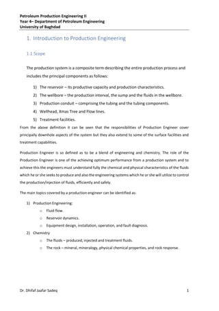
  • 4. Petroleum Production Engineering II Year 4– Department of Petroleum Engineering University of Baghdad 4 Dr. Dhifaf Jaafar Sadeq The field gasoil ratio rises continuously as the expanding gas cap reaches the wells situated higher up on the structure (c) Water Drive Drive energy in a water drive reservoir is provided primarily by water influx from an aquifer in pressure communication with the oil zone. In strong water drives, reservoir pressures are maintained, and the field gas/oil ratio remains low as water moves in to place the produced fluids. In a water drive reservoir, the oil zone in a communication with an aquifer providing the bulk of reservoir’s drive energy. As oil is produced, the water in the aquifer expands and moves into the reservoir, displacing oil. Depending on the aquifer’s strength, additional energy may be provided by solution gas expansion of the reservoir rock and its associated water. Recoveries from this type of reservoir will be the highest if the mobility of the oil is greater than that of the water. (d) Combination drive Drive energy in a combination drive reservoir is provided by a combination of two or more drive mechanism. The production trends reflect the characteristic of the dominant drive mwchanisim, which may change with time. The recovery may be high or low, depending on which drive mechanisms dominate. Figure (1.1) illistrates the reservoir performance for the tree majour primary drive mechanism
  • 5. Petroleum Production Engineering II Year 4– Department of Petroleum Engineering University of Baghdad 5 Dr. Dhifaf Jaafar Sadeq 1.3 Well productivity An oil and gas reservoir contains highly compressible hydrocarbon fluids at an elevated pressure and temperature and such as, the fluid stores up within itself considerable energy of compression. The efficient production of fluids from a reservoir requires the effective dissipation of this energy through the production system. Optimum utilization of this energy is an essential part of the successful completion. The productivity of the system is dependent on the pressure loss, which occurs in several areas of the flow system namely: • The reservoir • The wellbore • The tubing • The choke • The flow line • The separator The optimum distribution of energy between these various areas has a major bearing on the production effectiveness of well completion the selection of the appropriate completion string is fit for the purpose components which will control the cost effectiveness. The optimum distribution of energy between these various has a major bearing on the production effectiveness of well completion. The selection of the appropriate completion string is fit for the purpose components which will control the cost effectiveness. The pressure drop, which occurs across the reservoir, is defined as the inflow performance relationship or IPR. The pressure drop in the tubing and wellbore, post perforation, is that which occurs in lifting the fluid from the reservoir to the surface and it known as the vertical lift performance (VLP), or the tubing performance relationship (TPR). This is a frictional pressure drop caused by the flow of fluids through the casing and production tubing to the well head. In addition to overcoming the frictional pressure drop it is also necessary to have sufficient energy in the reservoir fluid to overcome the hydrostatic head required for the fluid to reach the surface from reservoir depth and to maintain the stipulated wellhead pressure which is required to feed the reservoir fluids into the production phase separator at its optimum operation pressure.
  • 6. Petroleum Production Engineering II Year 4– Department of Petroleum Engineering University of Baghdad 6 Dr. Dhifaf Jaafar Sadeq The pressure drop across the reservoir, the tubing and in fact the choke is rate dependent and these relationships therefore define the means by which we can optimize the production of the fluid from the reservoir. In some cases, these will impose significant limitations on the extent to which we can utilize and optimize the dissipation of this energy. These are discussed below: (1) Limited reservoir Pressure – in cases where the reservoir pressure is limited, it may not be feasible to achieve a significant and economic production rate from the well. In such cases it may be necessary to either assist in maintaining reservoir pressure or arrest the production decline by the use of gas or water injection for re-pressurization. Alternatively, the use artificial lift technique to offset some of the vertical lift pressure requirements and thus increases the production capacity of the system may be implemented. Pressure drop across the wellbore can be reduced substantially by having a horizontal section in the wellbore. This basically increases the length of formation available for production, hence increasing the productivity index, PI, of the well. (2) Minimum Surface Pressure – on arrival at the surface, the hydrocarbon fluids re fed down a pipeline through the choke and a production manifold to the production separator, where phase separation is allowed to take place. The production rates of oil, gas and water are measured here prior to the separate phases, oil, gas and water, being sent to various treatment facilities for further processing. To be able to allow the fluids to be driven through the initial separation process and in fact to provide some of the energy required for the process itself and to maximize the production rate, it will be necessary to have the minimum possible wellhead pressure that will be greater than the sum of the frictional pressure drop between the wellhead and the separator and the operating pressure of the separator itself (normally 100 to 200 psig). 1.4 The composite production system The composite production system is comprised of the production casing, the subsurface well completion, the wellhead, the choke and the flowlines to the production separator, the production separation process itself and the facilities used for transferring the produced fluids to their intended destinations.
  • 7. Petroleum Production Engineering II Year 4– Department of Petroleum Engineering University of Baghdad 7 Dr. Dhifaf Jaafar Sadeq 1.4.1 General description The energy stored within the reservoir is available to cause the flid to flow from the reservoir to the wellbore and then to the surface. The design of a production system that efficiently uses this available energy to maximize the production from the reservoir to the wellhead is fundamental to efficient well completion design and the responsibility rests with the production technologist. During the production of oil from the reservoir to a storage tank, the oil has to flow through a variety of restrictions that will consume some of the energy stored within the compressed fluids and controlled by their pressure and temperature. The combined system of the reservoir, the wellbore and the surface treatment facilities is generally referred to as the composite production system ( Figure (1.2)) Figure (1.2) Composite Production System
  • 8. Petroleum Production Engineering II Year 4– Department of Petroleum Engineering University of Baghdad 8 Dr. Dhifaf Jaafar Sadeq 1.5.2 Utilization of Reservoir Pressure In the development of a hydrocarbon reservoir, the energy stored up within the compressed state of the reservoir flids has to, in the majority of cases, overcome the total pressure loss in the producing system. Based upon a fixed operating pressure for the separator, we can formulate the pressure loss distribution as follows: 𝑃𝑅𝐸𝑆 = ∆𝑃𝑅𝐸𝑆 + ∆𝑃𝑊𝐵 + ∆𝑃𝑃𝑇 + ∆𝑃𝑆𝑈𝑅𝐹 + ∆𝑃𝐶𝐻𝑂𝐾𝐸 + 𝑃𝑆𝐸𝑃 (1.1) Where, 𝑃𝑅𝐸𝑆 is the initial or average pressure within the well drainage area in the reservoir. ∆𝑃𝑅𝐸𝑆 is the pressure loss caused by the flow of fluid within the reservoir to the wellbore. ∆𝑃𝑊𝐵 is the total pressure loss generated by the design of the fluid entry into the wellbore. ∆𝑃𝑃𝑇 is the pressure loss caused by fluid flowing up the production tubing string. ∆𝑃𝑆𝑈𝑅𝐹 is the pressure loss generated in the Xmas tree, production manifold and surface flowlines. ∆𝑃𝐶𝐻𝑂𝐾𝐸 is the pressure loss across the choke. 𝑃𝑆𝐸𝑃 is the required operating pressure for the separator. The pressure drop required to bring the fluids from the wellbore to the wellhead can be calculated from the following equation: ∆𝑃𝑅𝐸𝑆 = ∆𝑃𝐹 + ∆𝑃𝐻 (1.2) Where, ∆𝑃𝐹 is the frictional pressure drop in the production tubing which is a function of the fluid velocity. ∆𝑃𝐻 is the hydrostatic head between the wellbore and the wellhead which is dependent on the density of the fluids present in the tubing, the vertical distance between the wellbore and the wellhead and gravity. ∆𝑃𝐻= ρgh Equation (1.1) can be rearranged to give,
  • 9. Petroleum Production Engineering II Year 4– Department of Petroleum Engineering University of Baghdad 9 Dr. Dhifaf Jaafar Sadeq (𝑃𝑅𝐸𝑆 − 𝑃𝑆𝐸𝑃) = ∆𝑃𝑅𝐸𝑆 + ∆𝑃𝑊𝐵 + ∆𝑃𝑃𝑇 + ∆𝑃𝑆𝑈𝑅𝐹 + ∆𝑃𝐶𝐻𝑂𝐾𝐸 (1.3) Where, (𝑃𝑅𝐸𝑆 − 𝑃𝑆𝐸𝑃) is pressure drop available for the production system and hence will determine the rate at which the fluids can be produced to the surface. All the pressure drop terms in equation (1.3) are rate dependent and hence the total system pressure drop can be calculated as: ∆𝑃𝑇𝑂𝑇𝐴𝐿 = [∆𝑃𝑅𝐸𝑆 + ∆𝑃𝑊𝐵 + ∆𝑃𝑃𝑇 + ∆𝑃𝑆𝑈𝑅𝐹 + ∆𝑃𝐶𝐻𝑂𝐾𝐸 + 𝑃𝑆𝐸𝑃]𝑄 (1.4) Thus, each of pressure drops can be minimized either individually or collectively to give the maximum production rate for the available pressure drop. This is known as the production system optimization. The following text introduced the techniques normally used to minimize these pressure drops to provide a maximum potential production rate. To reduce the pressure loss due to flow in the reservoir it is necessary to reduce the resistance to flow. This can be accomplished either by reducing the formation rock resistance, e.g., increasing the permeability by acidization or fracturing or by reducing the resistance to flow due to the fluid properties, e.g. viscosity by utilizing thermal recovery techniques. These alternatives are normally too costly to be readily applicable expect in specific situations, e.g., chalk reservoirs or with very heavy crude oil reservoirs and may involve considerable technical risk. The pressure loss due to the bottom hole completion method has to be specified as part of completion design and as such is a major area for production optimization. It is likely that detailed consideration given to some aspects in this area sch as perforation shot density and length of perforated interval could be very beneficial to maximizing the production capacity of the system. Consideration must also be given to the possible use of a horizontal well instead of vertical or deviated well. In some cases, multi-lateral wells may be looked at. Again, as with the bottom hole completion pressure loss, the vertical lift pressure loss in the production tubing is a major area for optimization, as not only does the engineer have to specify the length and diameters of all sections of the tubing string but also all the specific completion components used in the string. Careful design in this area should provide significant productive capacity. The surface flowline pressure loss is relatively less important in that it is easily controlled even after the event. The diameter of the flowlines can be increased to compensate for the number of bends and
  • 10. Petroleum Production Engineering II Year 4– Department of Petroleum Engineering University of Baghdad 10 Dr. Dhifaf Jaafar Sadeq valves used in the system. Also the length of the flowline can be shortened through innovative facilities design of the surface production facilities and layout. Even if mistakes were made during the initial design, facilities can be upgraded without having to outlay too much capital. Little flexibility exists to minimize choke size as it is required to give a specific pressure drop for known flowrate to provide stability to the production separator. 1.5 Supplementary Reservoir Energy The increase in production rate could attained by supplementing the natural reservoir energy through either: 1- Increasing the reservoir pressure. Or 2- Providing more energy for the vertical lift process.