SSP 608 The Audi 1.6l and 2.0l 4 cylinder TDI engines.pdf
1. Audi
Audi
Vorsprung durch Technik
Service Training
608
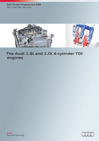
The Audi 1.6l and 2.0l 4-cylinder TDI
engines
All rights reserved.
Technical specifications are subject to
change.
Copyright
AUDI AG
I/VK-35
service.training@audi.de
AUDI AG
D-85045 Ingolstadt
Technical status 04/12
Printed in Germany
A12.5S00.92.20
Self Study Programme 608
For internal use only
2. 2
608_001
The modular design principle has been applied both to the core
assemblies (basic engine assembly, cylinder head and valvegear)
and to the attachments (close-coupled exhaust gas treatment
system and intake manifold with integrated charge air cooler).
The Modular Diesel Platform (MDP) will:
• meet future exhaust emission regulations,
• reduce CO2
emissions still further,
• cater to EU and NAR markets by providing an identical basic
concept and
• eliminate the need for universal use of SCR (selective catalytic
reduction) and accompanying engineering work in vehicle
platforms.
The new modular TDI® generation provides a harmonised basis for
future diesel engines. It comprises four cylinder engines with
displacements from 1.6 l to 2.0 l and power outputs from 66 kW
to 135 kW in the various exhaust emission versions.
Audi’s engine development engineers have translated this strategy
to the Modular Diesel Platform (MDP) in order that successive
platforms in the mid-range, compact and subcompact classes can
be supplied with identical or adapted engine assembly modules in
future.
This will allow for standardised procedures during the develop-
ment process and at production facilities within the Group, whilst
also ensuring an economical flow of materials.
Learning objectives of this Self Study Programme:
This self study programme describes the design and function of
the 1.6l/2.0l 4-cylinder TDI engine (MDP – Modular Diesel Plat-
form). After you have worked your way through this Self Study
Programme, you will be able to answer the following questions:
• How are the balancer shafts driven?
• What is the function of the exhaust flap in the exhaust system?
• What is the term used to describe the cooling system at cold start?
• What distinguishes the cylinder block of the 1.6l TDI from that of
the 2.0l TDI engine?
• In what order are the cylinder head valves fitted?
3. 3
• The Self Study Programme teaches a basic knowledge of the design and functions of new models, new
automotive components or new technologies.
It is not a Repair Manual! Figures are given for explanatory purposes only and refer to the data valid at the
time of preparation of the SSP.
For further information about maintenance and repair work, always refer to the current technical literature.
Note
Reference
Introduction
Brief technical description _________________________________________________________________________________________________________________________________ 4
Specifications ________________________________________________________________________________________________________________________________________________ 6
Engine mechanicals
Cylinder block _______________________________________________________________________________________________________________________________________________ 8
Crank mechanism ___________________________________________________________________________________________________________________________________________ 9
Balancer shafts _____________________________________________________________________________________________________________________________________________10
Drive mechanism for auxiliary units ______________________________________________________________________________________________________________________10
Toothed belt drive __________________________________________________________________________________________________________________________________________11
Cylinder head _______________________________________________________________________________________________________________________________________________12
Positive crankcase ventilation ____________________________________________________________________________________________________________________________15
Oil supply
Oil circuit ____________________________________________________________________________________________________________________________________________________16
Oil pump with integral vacuum pump ___________________________________________________________________________________________________________________17
Oil filter module ____________________________________________________________________________________________________________________________________________21
Variable camshaft timing
Introduction ________________________________________________________________________________________________________________________________________________23
Design _______________________________________________________________________________________________________________________________________________________23
Function _____________________________________________________________________________________________________________________________________________________24
Operating ranges ___________________________________________________________________________________________________________________________________________25
Exhaust gas recirculation
Exhaust emission standards ______________________________________________________________________________________________________________________________26
Installation list for exhaust gas recirculation system __________________________________________________________________________________________________26
Cooling system
Thermal management _____________________________________________________________________________________________________________________________________32
Switchable coolant pump _________________________________________________________________________________________________________________________________32
System overview ___________________________________________________________________________________________________________________________________________34
Coolant thermostat as 3/2-way valve ____________________________________________________________________________________________________________________39
Fuel system
Overview ____________________________________________________________________________________________________________________________________________________40
Exhaust system
Longitudinally mounted engines _________________________________________________________________________________________________________________________42
Transversely mounted engines ___________________________________________________________________________________________________________________________42
Engine management system
System overview ___________________________________________________________________________________________________________________________________________44
Service
Special tools and workshop equipment __________________________________________________________________________________________________________________46
Annex
Self Study Programmes ___________________________________________________________________________________________________________________________________47
Contents
4. 4
Brief technical description
Technical features of the 1.6l/2.0l 4-cylinder TDI engine (MDP)
608_008
608_021
608_049
Cylinder head with variable valve timing
(engines conforming to the EU6 exhaust
emission standard)
Oxidising catalytic converter and diesel particulate filter (transverse installation)
Cylinder block with integrated balancer shafts (2.0l TDI engine only)
Introduction
6. 6
608_002
Engine code CLHA
Type Four-cylinder inline engine
Displacement in cm3
1598
Stroke in mm 80.5
Bore in mm 79.5
Cylinder spacing in mm 88.0
Number of valves per cylinder 4
Firing order 1–3–4–2
Compression ratio 16.2 : 1
Power output in kW at rpm 77 at 3000 – 4000
Torque in Nm at rpm 250 at 1500 – 2750
Fuel Diesel to EN 590
Engine management system Bosch EDC 17
Maximum injection pressure in bar 1800 with solenoid valve injector CRI2-18
Emissions standard EU5
CO2
emission in g/km 99
Specifications
Torque/power curve of 1.6l TDI engine
Power output in kW
Torque in Nm
Engine speed [rpm]
608_059
Engine number
7. 7
608_003
Torque/power curve of 2.0l TDI engine
Engine with engine codes CRLB and CRBC
Power output in kW
Torque in Nm (CRLB)
Torque in Nm (deviation from CRBC)
Engine with engine code CUPA
Power output in kW
Torque in Nm
Engine speed [rpm]
Engine code CRBC CRLB CUPA
Type Four-cylinder inline engine Four-cylinder inline engine Four-cylinder inline engine
Displacement in cm3
1968 1968 1968
Stroke in mm 95.5 95.5 95.5
Bore in mm 81.0 81.0 81.0
Cylinder spacing in mm 88.0 88.0 88.0
Number of valves per cylinder 4 4 4
Firing order 1–3–4–2 1–3–4–2 1–3–4–2
Compression ratio 16.2 : 1 16.2 : 1 15.8 : 1
Power output in kW at rpm 110 at 3500 – 4000 110 at 3500 — 4000 135 at 3500 — 4000
Torque in Nm at rpm 320 at 1750 – 3000 340 at 1750 – 3000 380 at 1750 – 3250
Fuel Diesel to EN 590 Diesel to EN 590 Diesel to EN 590
Engine management system Bosch EDC 17 Bosch EDC 17 Bosch EDC 17
Maximum injection pressure in bar 1800 with solenoid valve
injector CRI2-18
2000 with solenoid valve
injector CRI2-20
2000 with solenoid valve
injector CRI2-20
Emissions standard EU5 EU6 EU5
CO2
emission in g/km 106 -1)
-1)
608_057
Engine number
1)
Data was unavailable at time of going to print.
8. 8
608_016
The cylinder block has the following technical features:
• Integrated balancer shafts above the crankshaft
• Short water jacket for rapid component heating
• Optimal cooling of the webs between the cylinders
• Integration of thermal management measures into the oil and
water circuits
Cylinder block
Balancer shaft
Insert in the oil pan
(designed as baffle plate with oil windage tray)
Oil pan
Overview
As with previous units, the cylinder block of the 1.6l / 2.0l TDI
engine is made of cast iron. The material in question is an alloy of
cast iron and nodular graphite (GG-GJL-250). In addition to having
a high tensile strength of 250 – 300 Nm/mm2
, this material boasts
a number of outstanding properties. The construction of the
cylinder block was also revised. For instance, the influence of the
threaded connections was shifted towards the bottom end of the
cylinder block by using low-seated cylinder bolt threads.
The net effect is an optimised distribution of power flow within the
engine block structure. This results in higher pre-compression of
the combustion chamber stopper as well as providing a more
homogeneous pressure distribution across the full circumference
of the cylinder head gasket. In addition, the cylinders are finished
by bolting a honing plate to the engine block. This allows the
cylinder heads to be mounted without warping, thereby reducing
prestress in the piston rings.
Cylinder block
Engine mechanicals
9. 9
608_014
Differences between the 1.6l and 2.0l TDI engines
Crank mechanism
608_015
Engine timing
chain sprocket
Oil pump chain sprocket Balancer shaft 1
Balancer shaft 2
Unlike the 2.0l TDI engine, the lower-displacement engine version
does not have balancer shafts. For this reason, the cylinder block
was adapted in these areas.
Components:
• Forged crankshaft mounted in five bearings
• For weight reasons, only four counterweights are used
• Cracked trapezoidal conrods
• Bowl pistons without valve pockets
• A single annular oilway
• supplied with cooled oil for cooling the piston crown
10. 10
Balancer shafts
608_034
Drive mechanism for auxiliary units
Balancer shaft 2
Crankshaft
Balancer shaft 1
Roller bearing
Roller bearing
Idler gear
for direction reversal
608_035
Crankshaft vibra-
tion absorber
A/C compressor
Alternator
Automatic tensioning pulley
To neutralise second order free inertial forces, use is made of a
balancer shaft system which is integrated in the cylinder block over
the crankshaft.
Vibration is combatted by dual counter-rotating shafts with coun-
terweights rotating at twice the speed of the engine. The direction
of rotation of the second shaft is reversed by an idler gear.
Drive is provided by the crankcase through helical-cut gears on the
output side. The shafts and the idle gear are located radially and
axially by a roller bearing. The bearings are lubricated with oil
spray from the cylinder block. Roller bearings lubricated with oil
spray have less of a drag effect at low temperatures and high
engine speeds.
The auxiliary unit mount supports the alternator and the A/C com-
pressor. An automatic belt tensioner driven by the crankshaft via
the vibration damper ensures that the poly V-belt is tensioned
correctly.
11. 11
Toothed belt drive
608_023
Camshaft sprocket Deflection pulley
Automatic tensioning pulley
Crankshaft
Deflection pulley Coolant pump High pressure
fuel pump
Interposed deflection pulleys provide increased wrap-around of the
chain sprockets.
The timing gear is fitted with a high-mileage toothed belt1)
. The
toothed belt runs from the crankshaft to the tensioning pulley, and
via the camshaft sprocket to the high pressure pump drive and the
switchable coolant pump.
1)
For information on replacement of the toothed belt, please refer to the applicable version of "Strict Maintenance Operations".
12. 12
Cylinder head
10 Intake camshaft timing adjustment valve 1 N205
11 Needle bearing
12 Bearing frame with camshafts
13 Roller-type cam follower
14 Camshaft valves 1
15 Camshaft valves 2
16 Cylinder head
17 High pressure exhaust recirculation duct
18 Distributor rail
608_022
1)
The figure shows the EU6 version.
Needle bearing
Special features of the cylinder head1)
are the "offset radial valve
arrangement", a split coolant jacket and a vertical intake manifold
flange.
The cylinder head comprises two components: firstly, the bearing
frame with integral camshafts (integrated valvegear module) and,
secondly, the cylinder head with fittings.
The camshaft tubes are inserted into the enclosed bearing frame
to create the integrated valvegear module. With this method, the
finish-machined bearing frame is mounted in a fixture, and the
finish-ground, heated cam elements and the encoder wheel are
held in the correct position in the bearing frame by a joining
cassette.
Having been fitted with end pieces and supercooled, the camshaft
tubes are then passed through the frame mounting points and the
heated cams. When the temperatures of the components are
equalised, both camshafts are mounted inseparably in the inte-
grated valvegear module.
This method allows the camshaft mounting to be designed for
high rigidity and low weight. To minimise friction, there is a needle
bearing on the output side of the camshaft.
The thermal joining method described here is used for the first
time in diesel engines of the Volkwagen Group. Previously, the
components were press-fitted hydraulically.
Legend of figure on page 13:
1 Fuel pressure regulating valve N276
2 High pressure fuel reservoir
3 Fuel pressure sensor G247
4 Clamping elements
5 Injectors
6 Positive crankcase ventilation and vacuum reservoir
7 Cylinder head cover
8 Pressure accumulator of the variable valve timing
9 Intake manifold module with integrated charge air cooler
14. 14
Arrangement of intake and exhaust flaps
Coolant jacket in cylinder head
To increase heat dissipation in vicinity of the combustion chamber,
the water jacket was split into lower and upper water jacket cores.
Both cores are mounted independently of one another in the
gravity die, and not conjoined in the casting. A defined cross
section which limits the upper volumetric flow is produced on the
control side by mechanical machining.
Upper water jacket
Lower water jacket in proximity
to the combustion chamber plate
Defined cross section Cylinder head outlet
608_043
Intake side
Exhaust side
First exhaust flap
of second cylinder
First
cylinder
First intake valve
of second cylinder
Intake air
Exhaust gases
608_036
Due to the offset radial valve configuration, the intake and exhaust
flaps are arranged one behind the other as seen from the intake
manifold flange side. This allows each of the camshafts to actuate
an intake valve and an exhaust flap. Compared to the predecessor
model, the ducts were redesigned to allow for the modified valve
arrangement. The focus was placed on increasing maximum
through-flow at good swirl rates.
The absence of swirl flaps was compensated by integrating a seat
swirl chamfer in each of the intake ports. This ensures that a good
swirl effect is maintained throughout the valve stroke. In addition,
the intake flange was arranged vertically to allow the use of an
intake manifold with integrated charge air cooling system in the
available installation space.
The heater flange with ventilation socket merges the coolant flows
at the common outlet to the heater heat exchanger. When the
engine is cold, the coolant in the lower and upper water jacket
cores is diverted towards the heater heat exchanger via the EGR
cooler.
Second exhaust flap
of second cylinder
Second intake valve
of second cylinder
15. 15
Positive crankcase ventilation
608_051
Vacuum reservoir
Pressure control valve
Fine oil separation
(cyclones)
Heating resistor
(crankcase breather) N79
(cold climates only)
Gravitational valve for oil recirculation
Oil return from fine oil separator
The cylinder head cover is made of polyamide. Its principal task is
to seal the cylinder head and integrate the vacuum reservoir.
Additional functions, such as the separation of coarse and fine of
the oil from the blow-by gases and pressure regulation in the
cylinder crankcase, are also integrated. The blow-by gases flow
from the crank chamber into the coarse oil separator through
small ports and then from the crank chamber into the cyclones.
Fine oil separation takes place here. After passing through the
cylones, the blow-by gases flow to the pressure control valve. In
addition, they are fed into the combustion chamber through the
intake manifold.
16. 16
Oil circuit
608_024
Oil pressure accumulator for variable camshaft timing
Longitudinally mounted
oil filter module
Camshaft oil gallery
Oil gallery of the
hydraulic tappets
Crankshaft oil gallery
Turbocharger oil supply
Oil pressure switch
F22
Oil pressure switch for
reduced oil pressure
F378
Piston cooling jets Oil level and temperature sensor
G266
Two-stage oil pump
Oil supply
17. 17
Oil pump with integral vacuum pump
608_017
Drive via
separate toothed belt
Oil/vacuum pump integrated in the oil pan.
Oil pump toothed belt cover
with integrated crankshaft ring seal
Connections to the vacuum supply and oil circuit
608_038
Oil pressure control valve
N428
Vacuum line from cylinder block
to vacuum equipment
Combined oil/vacuum pump integrated the oil pan
Oilway to main oil gallery
The combined oil/vacuum pump is located in the oil pan and
bolted to the cylinder block from below. It is driven by the crank-
shaft via the toothed belt drive. The toothed belt is immersed in
oil and has no belt tensioner; pretensioning is defined by the axial
spacings between components. This ensures ideal friction condi-
tions in the duopump drive.
In addition to the vacuum line, the oil pressure control valve N428
is integrated in the cylinder block via the oil pan. It is connected to
the vacuum line via ports in the vacuum pump and in the cylinder
block.
18. 18
2
1
608_025
Design
Adjustment ring
Input gear
Housing
Oil pressure relief valve Oil pump cover
Rotor with
vane cells
Control spring
Intake manifold
Rotor with
vacuum pump vane
Control piston
Vacuum
pump cover
Double flutter valve
Flutter valve
Component overview
The pump is a vane cell pump with an excentrically mounted
adjustment ring. To reduce the required drive output, the oil pump
has a volumetric flow control mechanism.
The delivery characteristic can be adjusted using a rotatably
mounted adjustment ring. By applying oil pressure to the adjust-
ment ring via a control surface, it can be swivelled against the
force of the control spring.
A specially shaped intake manifold ensures reliable engine oil
intake from the oil pan, even when the vehicle is subjected to high
transverse acceleration.
The vacuum pump induces air from the brake servo through a
vacuum line and ports in the cylinder block.
The extracted air flows through flutter valves into the cylinder
block and ventilates its inner chamber. This air is then admitted
into the combustion chamber via the engine breather as blow-by
gas.
The double flutter valve provides a cross section which is large
enough to expel the oil into the vacuum pump chamber. This helps
to keep drive torque to a minimum, even at low temperatures.
Oil pressure control
608_078
Oil
pressure
[bar]
Engine speed [rpm]
The oil pump operates in two pressure stages, which are activated
in dependence on engine speed.
1 Low pressure stage: oil pressure 1.8 – 2.0 bar
2 High pressure stage: oil pressure 3.8 – 4.2 bar
19. 19
608_026
608_055
Function
Adjustment ring
Control spring
Control surface
Vane cells
Small delivery chamber
Control piston
Oil pan
Control piston spring Control piston
Oil pressure from the oil
gallery
Non-return valve
Low delivery rate
At low engine speeds, the oil pressure control valve N428 ener-
gised by terminal 15 is connected to ground by the engine control
unit and opens the active oilway to the control piston. The oil
pressure now acts on both faces of the control piston, pushing the
piston against the control piston spring and opening the oilway to
the control surface of the adjustment ring.
The oil pressure acts on the control surface. The resultant force is
greater than that of the control spring and swivels the adjustment
ring counterclockwise into the centre of the vane cell pump,
thereby reducing the delivery space between the vane cells.
The lower pressure stage is activated in dependence on engine
load, engine speed, oil temperature and other operating param-
eters, reducing the drive output of the oil pump.
Oil pressure control valve N428
Active oilway
20. 20
608_027
608_056
Large delivery chamber Support bracket
Note
The maximum rate of delivery is always available when the solenoid valve is deenergised.
Oil pan
Control piston spring
Oil pressure from the oil gallery
Non-return valve
High delivery rate
In the upper engine speed range or at high engine load (full-
throttle acceleration), the oil pressure control valve N428 is
disconnected from ground by the engine control unit J623 in order
to vent the active oilway. The force of the remaining surface under
oil pressure is less than the force of the control piston spring and
closes the oilway to the control surface of the adjustment ring. In
the absence of oil pressure, the control spring swivels the adjust-
ment ring clockwise about the counter-bearing. The adjustment
ring now swivels out of its centre position and enlarges the delivery
space between the individual vanes. Oil delivery is increased by
enlarging the spaces between the vane cells.
The higher volumetric oil flow is countered by the oil ports and by
crankshaft bearing play, causing the oil pressure to increase. This
made it possible to realise a volume-controlled oil pump with two
pressure stages.
Control edge
Control piston Oil pressure control valve N428
Active oilway
21. 21
Oil filter module
608_045
Filter cartridge
Oil feed line
from the oil pump
Oil return line
to the engine lubrica-
tion points
Coolant feed line
to the oil cooler
Oil pressure
switch
F22
Oil pressure switch
for reduced oil
pressure F378
Coolant return line
from the oil cooler
Oil cooler
Longitudinally mounted engines
Depending on the engine's installation position, there are two
different oil filter modules.
Longitudinally mounted engines
The oil filter module for longitudinal engine installation comprises
the following components:
• Upright oil filter housing with oil drain valve
• Filter cartridge
• Oil pressure switch for reduced oil pressure F378 (0.3 – 0.6 bar)
• Oil pressure switch F22 (2.5 – 3.2 bar)
In addition, the oil filter module consists of the oil cooler, which is
mounted to the side of the oil filter module, as well as the oil filter
bypass valve and oil cooler bypass valve.
22. 22
Transversely mounted engines
608_046
Coolant return line
from the oil cooler
Oil pressure switch
for reduced oil
pressure F378
Filter cartridge
Coolant feed line
to the oil cooler
Oil cooler
Oil pressure
switch F22
In addition, the oil filter module comprises the oil cooler, which is
mounted to the side of the oil filter module, as well as the oil filter
bypass valve and the oil cooler bypass valve.
Oil filter bypass valve
Oil feed line
from the oil pump
Oil return line
to the engine lubrica-
tion points
Components
• Upright oil filter housing with oil drain valve
• Filter cartridge
• Oil pressure switch for reduced oil pressure F378 (0.3 – 0.6 bar)
• Oil pressure switch F22 (2.5 – 3.2 bar)
23. 23
Camshaft sensor configured as a Hall
sender G40 on an adjustable camshaft
608_021
Swivel motor
Piston pressure accumulator
608_037
1 Exhaust: variable opening
2 Intake: variable opening
3 Intake: variable closing
Key:
Design
608_053
Advance: both intake valves open simultaneously
Retard: only the rear intake valve on the “exhaust side” opens;
opening of the second intake valve is delayed
Mechanical locking bolt
Swivel motor (stator)
Swivel motor (rotor)
Spring
Cover
Cover with gear
Solenoid coil for
camshaft timing adjustment valve 1
N205
Control valve of camshaft timing adjustment valve 1
Introduction
In addition to reducing raw emissions, future technical develop-
ment efforts will focus on cutting fuel consumption. A possible
solution is to use a variable valvegear. A charge motion can be
induced by using a variable intake, rendering a swirl flap superflu-
ous. Another alternative is to adapt the intake valve timing for
advanced or retarded closing, thereby allowing NOx
and CO2
emis-
sions to be reduced. Compression can also be effectively reduced
by means of a variable intake valve timing mechanism. This would
result in lower compression temperatures and, in turn, in reduced
NOx
emissions.
Variable camshaft timing is only used in vehicles which meet the
EU6 exhaust emission standard. Multiple valvegear variables can
be controlled by using a phase adjuster in combination with a
mixed intake and exhaust camshaft configuration.
This technical innovation allows:
• optimised volumetric efficiency at full throttle
• optimised emissions and fuel efficiency through variable (and
thus more effective) compression
• maximum expansion loop utilisation
• high compression ratios at cold start
Variable valve timing is provided by means of a swivel motor.
At engine start, the swivel motor is mechanically locked in
the advance position by a locking bolt until the required oil pres-
sure is achieved.
The active adjustment range for the intake and exhaust flaps is 50°
of crank angle after retard.
Valve
travel
Variable camshaft timing
24. 24
608_010
Piston pressure accu-
mulator
Solenoid coil for camshaft
timing adjustment valve 1
N205
Mechanical locking bolt
Swivel motor (stator)
Swivel motor (rotor)
Non-return valve
Mesh oil filter
The swivel motor is supplied with pressurised oil by the volume-
controlled oil pump via a separate pressure line in the cylinder
head. The camshaft is adjusted by the engine control unit by means
of a 4/2-way proportional valve, which is activated in a pulse-
width-modulated manner. The inner vane ring (rotor) of the swivel
motor is connected to the camshaft.
The outer ring (stator) is fixed to a gear which engages a gear on
the driven camshaft. The camshaft is adjusted relative to the crank-
shaft by applying oil pressure to working chambers (A) and (B)
between the rotor and stator.
Function
Control valve from camshaft
timing adjustment valve 1
608_054
608_060
Piston pressure
accumulator
Camshaft timing
adjustment valve 1
N205
Control valve
Resetting spring
Swivel motor (rotor)
Swivel motor (stator)
Camshaft
Airflow – at retarded ignition timing during the intake cycle Sectional view of swivel motor
25. 25
C D
E
F
N205
A
A
B
B
C D
E
F
N205
A
B
A
B
A B
608_013
Operating ranges
Key:
Working chambers in the swivel motor
A Oil pump
B Engine lubrication system
C Mesh oil filter
D Nonreturn valve
E Piston pressure accumulator
E1
: Start of charging at approx. 0.6 bar
E2
: End of charging at approx. 1.8 bar
F Camshaft adjuster (swivel motor)
N205 Intake camshaft timing adjustment valve 1
Adjustment to retard
Adjustment to advance
The camshaft is locked in the "advance position". The spring-loaded
differential pressure bolt is released by the pressure of the engine
oil. Camshaft adjustment valve 1 N205 opens working chamber (A),
releasing the oil pressure into the return line. The oil pressure from
the pressure accumulator in working chamber (B) displaces the
swivel motor towards the "retard" position.
The oil pressure is admitted to working chamber (A) through
camshaft adjustment valve 1 N205, thereby advancing the
rotor towards working chamber (B).
Continuously variable valve timing is achieved by pulse-width-
modulated activation.
608_012
A swivel motor of the camshaft adjustment system must be
subjected to a high volumetric oil flow during the adjustment
cycle in order to ensure rapid control response. The camshaft
adjustment system is supplied with oil by a two-stage, volume-
controlled oil pump. To ensure rapid camshaft adjustment in the
first stage at a low pressure level, a pressure accumulator was
integrated in the camshaft adjuster. This pressure accumulator
ensures a sufficient supply of oil, whereby the holding pressure
inside the pressure accumulator can be up to 1.8 bar. The cam-
shaft timing adjustment valve 1 N205 dictates when the pressure
accumulator releases its oil into the corresponding port on the
swivel motor. The camshaft timing adjustment valve 1 is activated
by the engine control unit J623 in a pulse-width-modulated
manner.
In the unpressurised oil chamber, the oil is expelled from the
swivel motor and forced into the return line. If the gallery pressure
is less than the pressure inside the pressure accumulator during
camshaft adjustment, the adjustment cycle is always assisted by
the pressure accumulator. When the swivel motor reaches its end
position, the oil pressure in the pressure accumulator is restored
and the oil pressure in the feed line is at gallery pressure. The
camshaft timing adjustment valve 1 N205 can be set in such a way
that both working chambers are subjected to oil pressure. Depend-
ing on the oil pressure conditions in working chambers (A) and (B),
both the rotor and the camshaft are adjusted to either "advance" or
"retard". When the engine is shut off, the swivel motor is adjusted
to the "advance" position with spring assistance and locked.
26. 26
Installation list for exhaust gas recirculation system
The various versions of the exhaust gas recirculation system are
subdivided according to the applicable EU exhaust emission stand-
ards.
A common feature of all versions is an intake manifold module
with an integrated water-cooled charge air cooler with a flange or
distributor rail.
The task of the intake manifold module is to direct the fresh air
flow (including high and low pressure exhaust gas recirculation)
into the cylinder head. Depending on driving cycle, the compressed
air is cooled according to requirements by the integrated charge air
cooler. This is achieved by variation of the coolant flow rate by the
electrical coolant pump.
The engine is manufactured in the following emission versions.
• EU4 with high pressure exhaust gas recirculation
• EU5 with low pressure exhaust gas recirculation
• EU6, EU6 heavy duty and BIN5 with low and high pressure
exhaust gas recirculation.
Overview of exhaust emission standards
Exhaust emission standards
Features EU4 EU5 EU6 EU6 heavy duty BIN51)
/ULEV
High pressure exhaust recirculation x x x x
Low pressure exhaust recirculation x x x x
Cooled exhaust recirculation valve x x x x
Uncooled exhaust recirculation valve x x x x
SCR system (AdBlue) x x
EGR cooler x x x x x
Additional temperature sensor at radiator
outlet
x
4-way catalytic converter (modified coating on
the monoliths)
x
Cylinder pressure sensor 1 1 4
In vehicles in EU6 heavy duty and BIN5 configurations, the SCR
(selective catalytic reduction) system with cylinder pressure
sensors in the glow plugs is additionally installed. In the BIN5
configuration, use is made of an additional coolant temperature
sensor at radiator outlet G83.
Depending on exhaust emission standard, there are differences
between components, both in terms of type and how the exhaust
gases enter the intake system.
1)
The term "BIN" stems from the word "bag". During exhaust emission tests, the exhaust gases are collected in bags and analysed. Exhaust
emission standards are ranked from BIN10 to BIN5.
Exhaust gas recirculation
27. 27
Engines in EU4 configuration (high pressure exhaust recirculation)
608_041
Design of the exhaust gas recirculation (EGR) cooler
Exhaust gas inlet
Coolant feed line
Coolant return line
Divider plate
Uncooled/cooled
exhaust gases to
intake manifold
Vacuum connection
EGR bypass valve
Vacuum cell
Water-cooled EGR valve
Distributor rail
608_048
The EU4 version has a high pressure exhaust gas recirculation
system with a cooled EGR valve and an EGR cooler. The EGR cooler
has a vacuum-controlled bypass flap which is actuated by the
engine control unit depending on operating temperature.
Upstream of the exhaust turbocharger the recirculated exhaust
gases flow through a port in the cylinder head and into a water-
cooled exhaust gas recirculation valve mounted on the distributor
rail.
The recirculated exhaust gases are divided among the compressed
air and the cooled charge air via the distributor rail. This air
mixture is channeled to the cylinder head intake port.
28. 28
Engines in EU5 configuration (low pressure exhaust recirculation)
608_061
System overview
Oxidising catalytic converter
Diesel particulate filter
EGR cooler
Flex tube
Exhaust flap control unit
J883
The EU5 version has a low pressure exhaust recirculation system
with an uncooled EGR valve and an EGR cooler on the diesel par-
ticulate filter.
Downstream of the diesel particulate filter the recirculated
exhaust gases flow through the water-cooled EGR cooler to the
uncooled exhaust gas recirculation valve via a filter cartridge. From
here, the cooled exhaust gases are channeled to the exhaust
turbocharger compressor, optimally mixed with charge air and
admitted to the intake manifold system with integrated charge air
cooler.
To utilise the low pressure exhaust gas recirculation system across
the full mapped range, the complete exhaust gas flow from the
diesel particulate filter is shut off in a controlled manner by a
motor-operated exhaust flap.
This produces an excess pressure of approx. 30 – 40 mbar down-
stream of the particulate filter relative to the exhaust pressure
downstream of the exhaust flap. This excess pressure results in a
positive flow gradient (purging rate) via the EGR cooler and the
following EGR valve. The quantity of recirculated exhaust gas is
controlled by the EGR valve.
The 73° operating range of the exhaust flap is defined by:
• exhaust pressure downstream of the exhaust flap
• nominal exhaust pressure upstream of the exhaust flap
• mass flow through the exhaust flap
29. 29
Engines in EU6, EU6 heavy duty and BIN5 configurations (low and high pressure exhaust gas recirculation)
608_040
Condensate outlet
Exhaust intake from
diesel particulate
filter
Coolant feed line
EGR
servomotor
V338
Coolant return line
Divider plate
Cooled exhaust
gases to turbo-
charger
EGR
throttle valve
Design of the exhaust gas recirculation (EGR) cooler
Water-cooled EGR valve
Throttle valve 608_048
The EU6 version has low and high pressure exhaust gas recircula-
tion systems with cooled and uncooled EGR valves and an EGR
cooler in the low pressure exhaust gas recirculation system.
The exhaust gases are recirculated in the same way as in EU5
engines. Uncooled exhaust gases from the high pressure exhaust
gas recirculation system are fed in via a water-cooled EGR valve in
the distributor rail at defined operating points.
Transversely mounted engines Longitudinally mounted engines
Exhaust intake from
diesel particulate filter
Coolant feed line
Cooled exhaust
gases to turbocharger
EGR
throttle valve
EGR
servomotor
V338
Coolant return line
30. 30
Exhaust manifold module
608_079
The exhaust manifold module consists of the exhaust manifold,
the exhaust turbocharger integrated in the exhaust manifold, the
low pressure exhaust gas recirculation intake and the baffled
sound absorber. Use is made of an exhaust turbocharger with a
pneumatically actuated Variable Turbine Geometry (VTG) and a
position sensor.
The recirculated exhaust gases are not extracted at the turbine
housing, rather at the diesel particulate filter outlet. In the EU5
version, the full mass flow is always channeled through the turbo-
charger compressor by extracting the recirculated exhaust gases
downstream of the diesel particulate filter outlet.
The turbocharger can thus be operated with greater efficiency. This
allows higher charge pressures and higher volumetric efficiency to
be achieved at partial throttle in particular. A benefit of this is the
higher cooling capacity of the exhaust gas recirculation system,
which helps to reduce the mixing temperature of the fresh air and
recirculated exhaust gases.
The overall system was designed in such a way that the versions
with high and low pressure exhaust gas recirculation in EU4 and
EU6 configurations can be implemented modularly by modifying
the compressor housing and the exhaust manifold.
The acoustic characteristics of the exhaust turbocharger were
improved by using modified damping chambers in the baffled
sound absorber.
Exhaust turbocharger module for longitudinal installation
Vacuum cell
VTG actuating lever
Vacuum connection
Intake air from
air filter
Integral insulation
Oil return line
Blow-by gases
of the positive
crankcase
ventilation
system
To intake
manifold with
integrated
charge air
cooler
from EGR cooler
and EGR valve
Heater element for positive
crankcase ventilation N79
(cold-climate countries only)
Exhaust manifold with
integrated turbine
Oil feed line
31. 31
By way of improvement, the water-cooled charge air cooler for
diesel engines is integrated in the intake manifold as in the 1.4l
TFSI petrol engines. The heat sink comprises the coolant plates,
fins; top, base and side plates; and coolant connections. A separate
low temperature coolant circuit equipped with and air-to-water
heat exchanger provides demand-oriented charge air cooling in
combination with a variable-speed electrical coolant pump.
This has the following advantages:
• As the intake manifold temperatures are adjustable within
defined limits, the system can operate independently of the
intake air temperature and the recirculated exhaust gas.
• The result is a compact charge air circuit.
• Flow losses are reduced.
• Icing and condensation are avoided in the charge air cooler
• Synergy is achieved in particular by using the charge air cooler
as a high-performance low pressure exhaust gas recirculation
and cooler system
The charge air cooler integrated in the intake manifold is fully
brazed and made of aluminium. The intake and exhaust boxes are
subsequently welded to the heat sink.
Coolant flows through the coolant plates in a W configuration
according to the counterflow principle. Due to the special geom-
etry of the coolant plates, the coolant flow is distributed across the
width of the flat tube and simultaneously diverted. This makes for
effective heat transfer from the aluminium panel to the coolant.
Charge air cooler
Note
For information on the functioning of the low temperature coolant circuit, refer to p. 38 of this booklet.
608_019
Design
Throttle valve connection
Charge air cooler with coolant
connections and W-shaped
coolant plates
Connecting flange
to cylinder head
Charge air temperature
sensor after charge air
cooler G811
Charge air temperature
sensor before charge air
cooler G810
Charge pressure sender
connection G31
Channel to charge air cooler
32. 32
Switchable coolant pump
608_029
Thermal management
608_018
Cylinder head coolant valve
N489
Impeller with integrated
wobble plate
Axial-piston pump
Control valve seal
Compression spring for resetting
the control valve
Control valve (pot)
Annular piston
Annular piston ring seals
Guide bush with
coolant ducts
Pump casing
Bearing
Drive shaft
Cylinder head
coolant valve
N489
Coolant pump
The 1.6l/2.0l TDI engine has a thermal management system which
is designed to shorten the warm-up phase after a cold start and
channel the heat produced by the engine to where it can be advan-
tageously utilised to boost vehicle efficiency.
The focus here is on reducing intra-engine friction. Other goals are
to ensure the early availability of emission reduction measures and
to reduce the use of heating measures which impair fuel efficiency.
The overall cooling circuit comprises three sub-circuits:
• Secondary cooling circuit (micro circuit)
• Cylinder head
• EGR cooler of low pressure exhaust gas recirculation system
• Heater heat exchanger
• Electrical auxiliary coolant pump
• Primary cooling circuit (high temperature circuit)
• Cylinder block
• Engine and gear oil cooler
• Coolant thermostat (3/2-way valve)
• Main radiator
• Switchable coolant pump
• Cooling circuit with charge air cooling (low temperature circuit)
• Charge air cooler
• Front radiator
• Electrical auxiliary coolant pump
A switchable coolant pump is used in the thermal management
system for the 1.6/2.0l TDI engine. This coolant pump can be
switched on and off, allowing coolant circulation to be stopped
when the engine is cold. Static coolant heats up more quickly and
can bring the engine up to operating temperature more effectively.
A hydraulically actuated control valve (pot) activated by the cylinder
head coolant valve N489 slides over the rotating impeller and
prevents the coolant from circulating.
Cooling system
33. 33
608_007
Coolant pump function
608_039
Cylinder head coolant valve
N489 on
Cylinder head coolant valve
N489 off
Annular piston displaced
Control valve slid
over the impeller
Axial-piston pump
Impeller
Wobble plate with
race for axial piston
pump
Control valve retracted
Return port
open
The control valve can slide hydraulically over the impeller, thus
preventing coolant from being circulated. The impeller has an
integral cast-in stainless steel plate which acts as a wobble plate.
Static coolant
An axial piston pump integrated in the pump casing is actuated by
the wobble plate. The axial piston pump recirculates the coolant to
the cooling circuit via the cylinder head coolant valve N489
through the lifting motion of the wobble plate.
When the solenoid valve is energised, the return port to the
coolant circuit closes. The lifting motion of the axial piston pump
produces a hydraulic pressure at the annular piston. The control
valve slides over the impeller against the force of a pressure spring
and seals the impeller off from the cylinder block. No coolant is
circulated.
Coolant is circulated
If the solenoid valve is deenergised, the return port to the coolant
circuit opens, and the annular piston is pushed back by the com-
pression spring and restores the control valve to its original posi-
tion. The impeller is again free and the coolant begins to circulate.
The axial piston pump operates whenever the engine is running.
34. 34
15
13 14
1
2
3
6
7
8
10
11
17
12
18
4
5
16
9
608_073
Cooled coolant
Heated coolant
System overview
Key:
1 Coolant expansion tank
2 Heater heat exchanger
3 Auxiliary heater
4 Recirculation pump V55
5 Heating assistance pump V488
6 Coolant temperature sender G62
7 Coolant socket
8 EGR cooler
9 Cylinder head coolant valve N489
10 Coolant thermostat
11 Throttle valve
12 Engine oil cooler
13 Radiator fan V7
14 Radiator fan 2 V177
15 Radiator
16 Charge air cooling pump V188
17 Charge air cooler integrated in intake manifold
18 Radiator for charge air cooling
The following diagrams show the cooling system in the engine
version which meets the EU5 exhaust emission standard.
35. 35
15
13 14
1 2
3
6
7 8
10
11
17
12
18
4
5
16
9
Secondary cooling circuit (micro circuit, heating circuit)
Auxiliary heater operation
If the engine is cold, the thermal management system is started in
conjunction with the secondary cooling circuit, thereby ensuring
that the engine and interior are heated quickly. The switchable
coolant pump is activated via the cylinder head coolant valve
N489.
This stops the coolant from circulating in the engine block. The
electrical heating assistance pump V488 initiates the secondary
cooling circuit in a controlled manner, depending on the coolant
temperature in the cylinder head.
The driver's temperature preference is registered by the A/C
control unit and taken into consideration when the coolant pump
is activated.
The auxiliary heater is integrated in-line with the heater heat
exchanger without changeover valves. It has a separate circulation
pump V55.
The heating assistance pump V488 provides back-up in cold
ambient conditions in order to ensure that a minimum volumetric
flow is achieved at high coolant viscosity.
608_074
36. 36
15
13 14
1 2
3
6
7
8
10
11
17
12
18
4
5
16
9
Secondary cooling circuit – engine cooling requirements / high engine load
The switchable coolant pump is activated at increasing engine load
and engine speed. This ensures that the engine is cooled. After the
engine speed drops below a threshold level, the coolant pump is
deactivated again and the engine is operated without coolant circu-
lation until the required coolant temperature is achieved.
The coolant pump is continuously activated when the coolant
temperature exceeds a threshold level at the cylinder head, indi-
cating that the engine is at operating temperature. When the
coolant pump is activated, it is ensured that a sufficient quantity of
coolant flows through the cylinder head. For this purpose, the
engine has a thermostat with an integrated short circuit (refer to
p. 39).
Key:
1 Coolant expansion tank
2 Heater heat exchanger
3 Auxiliary heater
4 Recirculation pump V55
5 Heating assistance pump V488
6 Coolant temperature sender G62
7 Coolant socket
8 EGR cooler
9 Cylinder head coolant valve N489
608_075
Cooled coolant
Heated coolant
10 Coolant thermostat
11 Throttle valve
12 Engine oil cooler
13 Radiator fan V7
14 Radiator fan 2 V177
15 Radiator
16 Charge air cooling pump V188
17 Charge air cooler integrated in intake manifold
18 Radiator for charge air cooling
37. 37
15
13 14
1 2
3
6
7 8
10
11
17
12
18
4
5
16
9
Primary cooling circuit (high temperature circuit) – coolant at operating temperature
If the coolant is at operating temperature, the coolant thermostat
opens and enters control mode. The radiator (main radiator) is
integrated in the cooling circuit.
608_076
The coolant thermostat controls the engine outlet temperature
and is located in the main radiator feed line.
38. 38
15
13 14
1 2
3
6
7 8
10
11
17
12
18
4
5
16
9
Low temperature cooling circuit – coolant circuit for charge air cooling
The intake manifold temperature is used as a reference variable for
activating the charge air cooling circuit. After this tagert tempera-
ture is achieved, the intake manifold temperature is regulated by
activating the charge air cooling pump V188.
Key:
1 Coolant expansion tank
2 Heater heat exchanger
3 Auxiliary heater
4 Recirculation pump V55
5 Heating assistance pump V488
6 Coolant temperature sender G62
7 Coolant socket
8 EGR cooler
9 Cylinder head coolant valve N489
608_077
Cooled coolant
Heated coolant
10 Coolant thermostat
11 Throttle valve
12 Engine oil cooler
13 Radiator fan V7
14 Radiator fan 2 V177
15 Radiator
16 Charge air cooling pump V188
17 Charge air cooler integrated in intake manifold
18 Radiator for charge air cooling
39. 39
Coolant thermostat as 3/2-way valve
608_005
608_006
Secondary cooling circuit (micro circuit)
Primary cooling circuit (high temperature circuit, controlled)
open:
Short circuit
to coolant pump
from
cylinder block
from
cylinder block
The coolant thermostat is activated by an expanding wax element,
which begins to close the secondary cooling circuit when operating
temperature is reached. The primary cooling circuit is closed at the
same time.
is hereby entered
into by and
Connection to
main radiator
open:
Connection to
main radiator
is hereby entered
into by and
Short circuit
to coolant pump
40. 40
Overview
Fuel metering valve
N290
High pressure pump
CP4.1
Fuel temperature sensor
G81
Non-return valve
(throttle device)
Fuel filter
Fuel pressure sensor
G247
High fuel pressure 1800/2000 bar
Fuel feed pressure (demand controlled) 3.5 – 5.0 bar
Fuel return pressure from
the injectors 0.4 – 1.0 bar
Colour key:
approx.
0.4 – 1.0 bar
1800/2000 bar
approx. 0 – 1.0 bar
approx. 3.5 – 5.0 bar
to
engine
control
unit
J623
Battery
(positive)
Fuel system
41. 41
608_028
High pressure accumulator (rail)
Fuel pressure regulating valve
N276
Injectors
N30, N31, N32, N33
Baffle housing
Fuel pump (pre-supply pump)
G6
− with pressure limiting valve configured as a safety valve,
which opens at approx. 6.6 bar in EU5/EU6 configuration
− with working valve, which opens at 5.8 bar in EU4 configu-
ration
Fuel pump control unit
J538 (not in EU4 configuration)
Ground
42. 42
Transversely mounted engines
Longitudinally mounted
engines
Oxidising catalytic converter
Diesel particulate filter
EGR cooler
Flex tube
Flex tube
Exhaust flap control unit
J883
Exhaust flap control unit
J883
Centre silencer
Oxidising catalytic converter
Diesel particulate filter
Exhaust turbocharger
Exhaust manifold
Exhaust system
44. 44
System overview
Sensors
Air mass meter G70
Engine speed sender G28
Hall sender G40
Coolant temperature sender G62
Fuel temperature sender G81
Throttle valve potentiometer G69
Oil level/oil temperature sensor G266
Fuel pressure sensor G247
Accelerator pedal sender G79 and accelerator pedal position
sender G185
Exhaust gas recirculation potentiometer 2 G466
Charge pressure actuator position sensor G581
Brake light switch F
brake pedal switch F63
Charge pressure sensor G31
Oxygen sensor G39
Exhaust gas temperature sender 3 (after cat) G495
EGR temperature sensor G98 (EU4)
Exhaust gas temperature sender 1 G235
Differential pressure sender G505
Diagnostic port
Engine control unit
J623
Auxiliary signals:
− Cruise control system
− Speed signal
− Start request to engine control unit (Kessy 1 + 2)
− Terminal 50
− Crash signal from airbag control unit
Charge air temperature sensor after charge air cooler G811
Charge air temperature sensor before charge air cooler G810
Oil pressure switch F22
Oil pressure switch for reduced oil pressure F378
Exhaust gas temperature sender 4 G648
Coolant temperature sender at radiator outlet G831)
Combustion chamber pressure sender for cylinder 3 G6791)
Charge pressure actuator position sensor G581
NOx
sender G2951)
NOx
sender 2 G6871)
NOx
sender control unit
J5831)
NOx
sender control unit 2
J8811)
Private
CAN
bus
Engine management system
45. 45
Actuators
Injectors, cylinders 1 – 4
N30, N31, N32, N33
Automatic glow period control unit for J179
Glow plugs 1 – 4 Q10, Q11, Q12, Q13
Oil pressure control valve N428
Throttle valve control unit J338
Fuel metering valve N290
Fuel pressure regulating valve N276
Exhaust gas recirculation servomotor V338
(Low pressure exhaust gas recirculation)
Exhaust gas recirculation servomotor 2 V339
(High pressure exhaust gas recirculation)
Exhaust gas recirculation cooler change-over valve N345
(EU4)
Exhaust flap control unit J883
Heater element for positive crankcase ventilation N79
(cold-climate countries only)
Heating assistance pump V488
Oxygen sensor heater Z19
Fuel pump relay J17
Fuel predelivery pump G6
Auxiliary signals:
A/C compressor
Auxiliary coolant heater
Fan setting 1 + 2
Auxiliary air heater element Z35
1)
These components are for EU6 heavy duty and BIN5 configurations only
608_058
Cylinder head coolant valve N489
Fuel pump control unit J538
Charge air cooling pump V188
Charge pressure limitation solenoid valve N75
Reduction agent metering system control unit J8801)
Reduction agent injector N4741)
Reduction agent line heater Z1041)
Reduction agent pump V437
Reduction agent tank heater Z102
46. 46
Special tools and workshop equipment
Tensioning the timing belt Removing the high pressure pump drive gear
T10172 with T10172/11
608_071 608_072
T10489
608_064
T10490
Locking the crankshaft with round and oval chain sprockets
608_066
Removing and fitting the oxygen sensor
Locking the high pressure pump and camshaft Fitting the camshaft seal
T10491
608_068
T10493
T10492
608_069 608_070
Service
47. 47
Self Study Programmes
You will find further information on the technology of the 1.6l/2.0l TDI engine in the following Self Study Programme.
608_081
SSP 420 Audi 2.0l TDI Engine with Common Rail Injection System, order number: A08.5S00.45.20
Annex
48. Audi
Audi
Vorsprung durch Technik
Service Training
608
The Audi 1.6l and 2.0l 4-cylinder TDI
engines
All rights reserved.
Technical specifications are subject to
change.
Copyright
AUDI AG
I/VK-35
service.training@audi.de
AUDI AG
D-85045 Ingolstadt
Technical status 04/12
Printed in Germany
A12.5S00.92.20
Self Study Programme 608
For internal use only