SlideShare a Scribd company logo
1 of 23
Download to read offline
Kuwait National Petroleum Company (K.S.C)
Clean Fuels Project (CFP)
RESPONSE SHEET
Action Code: A-Accepted, N-Not accepted
Page 1 of 1
Vendor Document No: VP-2025JV8J10121-216-B06-001 Rev No.: 4 Status Code-
Transmittal No: Received Date:
Document Title : APC Functional Design Specification Document – Unit 216 - DHT
Serial No. COMPANY Comments VENDOR Response Action Code COMPANY Response
Comment on rev.3
1.
For Plants like U-116, inferential is required
against all analyzers of qualities to be controlled by
APC. These inferential needs to be updated by
both analyzer values and LAB results. Analyzer
locations are downstream to drier far off from all
possible MV’s contributing to possibility of
significant dead time. Moreover, with throughput
changes this dead time will continue to vary. FDS
needs to take these aspects in consideration.
Analyzer like Cloud point are typically known for
less reliability and requires use of inferential with
proper validations both from LAB data, its own
reading & other logics. Just mentioning inferential
will be attempted in phase-2 is not sufficient.
This is true also for all other units where direct
analyzer value is considered for control. (e.g.: U-
115,
Pg. 19)
Honeywell explained during the review of revision 1 FDS document that
getting inferential calculation for properties like gasoil sulphur and
cloud point is not always accurate. However, as KNPC has insisted
these variables will be included as inferential variables instead of
analyzer measurement and have to be carefully studied during phase 2
of the project
2.
CV16-21 (Bearing Vibrations) may be handled
additionally at DCS complex loops with over-ride
on Feed flow cutoff etc. as quick & safe measure.
(Same is valid for U-115, pg. 14-15)
Honeywell suggests that the vibrations are left at APC level and are
constraint variables for increasing the feed.
3.
3.2.7 Maximum Reactor Bed 5 temperature:
Typos in the formula: Change "Ma" to "Max"
Agreed. Will be modified in next revision
4.
Section 3.2 (Profit controller calculations)
When average temperatures are calculated all
temp tags should be considered .If temp indication
turns bad simply drop it from calculation. This is
the current practice in MAB.
The weighted average bed temperature calculation and the input
average temperature for the calculation are calculated as per the
licensor calculation provided by PSCJ. Honeywell suggests to retain
the same.
PSCJ : OK
Vendor Document Review Cover Sheet
Kuwait National Petroleum Company (K.S.C.)
Clean Fuels Project (CFP) Kuwait
KNPC Contract No. CFP/EPC/0054-MAB1, Purchaser Job No. JI-2025
Mina Abdullah Refinery
Purchase Order No. : 2025JV8J10121
Purchase Order Description : ADVANCE PROCESS CONTROL SYSTEM (PHASE - I)
Vendor Name : HONEYWELL KUWAIT KSC
Company Document Number : VP-2025JV8J10121-216-B06-001 Rev : 05
Vendor Document Number : VP-2025JV8J10121-216-B06-001 Rev : 05
Document Description / Title :
APC FUNCTIONAL DESIGN SPECIFICATION DOCUMENT -
UNIT-216 DIESEL HYDROTREATING UNIT
Equipment Tag Numbers :
PURCHASER APPROVAL STATUS
Status
Approval
Code
Code Description
 A APPROVED WITHOUT COMMENT - WORK MAY PROCEED
 B
APPROVED WITH MINOR COMMENTS– WORK MAY PROCEED -REVISE AND
RESUBMIT
 C
REVISE AND RESUBMIT – WORK MAY PROCEED SUBJECT TO INCORPORATION OF
COMMENTS INDICATED
 D APPROVAL NOT REQUIRED. INFORMATION ONLY. WORK MAY PROCEED
 F AS-BUILT / ACCEPTED AS FINAL
 R REJECTED - REVISE AND RESUBMIT. WORK MAY NOT PROCEED
 V VOID (DOCUMENT HAS BEEN CANCELLED / DELETED)
Purchaser’s review of this document does not relieve Vendor of the responsibility for correctness under the Purchase
Order. Permission to proceed does not constitute acceptance of design, detail and calculations, test methods or
materials developed or selected by the Vendor and does not relieve the Vendor from full compliance with the Purchase
Order or any other obligations, nor detract from any of the Purchaser’s rights.
Reviewing Engineer’s Full Name (IN BLOCK LETTERS), Sign and Date
Name: Sign: Disp.: Date:
04.12.2017
sairaja
S44279
S Khasnobis C&I
1 11.12.17
Kuwait National Petroleum Company (K.S.C)
Clean Fuels Project 2020
KNPC Contract No. CFP/EPC/0054-MAB1
PSCJ Job No. JI-2025
APC FDS
Unit 216 – DIESEL
HYDROTREATING UNIT
VP-2025JV8J10121-216-B06-001
REV. 04, 26-NOV-2017
Page 2 of 21
Record Of Revisions
Revision Page/Section Description
0 All Initial Release issued for comments
1 All Revised post FDS review meeting comments
2 All Revised post Rev. 1 comments
3 2/3 Revised post KNPC comments
4 All Revised post Rev. 3 comments
List Of Holds
Page/Section Description
Kuwait National Petroleum Company (K.S.C)
Clean Fuels Project 2020
KNPC Contract No. CFP/EPC/0054-MAB1
PSCJ Job No. JI-2025
APC FDS
Unit 216 – DIESEL
HYDROTREATING UNIT
VP-2025JV8J10121-216-B06-001
REV. 04, 26-NOV-2017
Page 3 of 21
Table of Contents
1.0 INTRODUCTION.............................................................................................7
1.1 Scope ...........................................................................................................................7
1.2 References...................................................................................................................7
2.0 PROCESS OVERVIEW...................................................................................9
2.1 Process overview........................................................................................................9
2.2 Existing Controls Analysis ......................................................................................13
2.3 Operating Targets and Constraints.........................................................................14
3.0 RMPCT APPLICATIONS ..............................................................................15
3.1 Diesel Hydro Treater (U216).....................................................................................15
3.1.1 Objectives ......................................................................................................15
3.1.2 Strategies.......................................................................................................15
3.1.3 Profit Controller functional design..................................................................16
3.2 Profit Controller Calculations..................................................................................18
3.2.1 Waited Average Bed temperature 1 to 3 .......................................................18
3.2.2 Weighted Average Bed temperature 4 ..........................................................19
3.2.3 Maximum Reactor Bed 1 temperature...........................................................19
3.2.4 Maximum Reactor Bed 2 temperature...........................................................20
3.2.5 Maximum Reactor Bed 3 temperature...........................................................20
3.2.6 Maximum Reactor Bed 4 temperature...........................................................20
3.2.7 Maximum Reactor Bed 5 temperature...........................................................20
3.2.8 H2/HC ratio calculation ..................................................................................20
3.3 Inferential ...................................................................................................................21
Kuwait National Petroleum Company (K.S.C)
Clean Fuels Project 2020
KNPC Contract No. CFP/EPC/0054-MAB1
PSCJ Job No. JI-2025
APC FDS
Unit 216 – DIESEL
HYDROTREATING UNIT
VP-2025JV8J10121-216-B06-001
REV. 04, 26-NOV-2017
Page 4 of 21
Figures
No table of figures entries found.
Kuwait National Petroleum Company (K.S.C)
Clean Fuels Project 2020
KNPC Contract No. CFP/EPC/0054-MAB1
PSCJ Job No. JI-2025
APC FDS
Unit 216 – DIESEL
HYDROTREATING UNIT
VP-2025JV8J10121-216-B06-001
REV. 04, 26-NOV-2017
Page 5 of 21
Tables
Table 2-1 DHT Operating Targets and Constraints...............................................................14
Table 3-1 U216 DHT Profit Controller – Controlled variables (CV).....................................17
Table 3-2 U216 DHT Profit Controller – Manipulated variables (MV) .................................18
Table 3-3 DHT Profit Controller Profit Controller – Disturbance variables (DV)................18
Kuwait National Petroleum Company (K.S.C)
Clean Fuels Project 2020
KNPC Contract No. CFP/EPC/0054-MAB1
PSCJ Job No. JI-2025
APC FDS
Unit 216 – DIESEL
HYDROTREATING UNIT
VP-2025JV8J10121-216-B06-001
REV. 04, 26-NOV-2017
Page 6 of 21
Abbreviations
Symbol Detailed description
APC Advanced Process Control
DCS Distributed Control System
PFS Process Flow Scheme
PEFS Process Engineering Flow Scheme
TAC Traditional Advanced Control
Kuwait National Petroleum Company (K.S.C)
Clean Fuels Project 2020
KNPC Contract No. CFP/EPC/0054-MAB1
PSCJ Job No. JI-2025
APC FDS
Unit 216 – DIESEL
HYDROTREATING UNIT
VP-2025JV8J10121-216-B06-001
REV. 04, 26-NOV-2017
Page 7 of 21
1.0 INTRODUCTION
Honeywell has been engaged by PSCJ for carrying out the Phase 1 activities of Advanced
Process Control System implementation for the MAB refinery as a part of Kuwait National
Petroleum Corporation (KNPC) Clean Fuels Project 2020 in Kuwait. As a part of phase 1
activity Honeywell has developed the APC Functional Design Specification (FDS) document.
The following FDS documents are develop
• Unit – 111 Crude Distillation Unit APC FDS
• Unit – 114 Hydrocracker Unit APC FDS
• Unit – 127 Continuous Cracker Reformer Unit APC FDS
• Unit – 213 Vacuum Rerun Unit APC FDS
• Unit – 214 Hydrocracker Unit APC FDS
• Unit – 112 Atmospheric Residue Desulpharisation Unit APC FDS
• Unit – 115 Kero Hydrotreater Unit APC FDS
• Unit – 116 Diesel Hydrotreater Unit APC FDS
• Unit – 117 Naptha Hydrotreater Unit APC FDS
• Unit – 111 Crude Distillation Unit APC FDS
• Unit – 212 Atmospheric Residue Desulpharisation Unit APC FDS
• Unit – 216 Diesel Hydrotreater Unit APC FDS
• System architecture and Interface FDS
This document gives the Functional Design Specification document for Unit-112 Atmospheric
Residue Desulphurisation Unit. This is based on the review of reference documents provided
by the Contractor and Honeywell’s experience in implementing Advanced Process Control
applications in such units.
1.1 Scope
Scope of this document includes ‘Advanced Process Control” functional design on the following
sections:
• Describe the basic process of the unit
• Summarize the DCS level control strategies for the unit as described in the PFS, PEFS
and Control Narrative document
• Specify the control strategies of APC for the unit
• Specify the basic APC design for the unit summarizing the Controlled Variables (CV),
Manipulated Variables (MV) and Disturbance Variables (DV)
• Specify the inferential control variables used in the APC and possible inputs to the
inferential
• Specify the calculations used in the APC system and the inputs used in the
calculations
1.2 References
• Process Description - P6002MAB-216-10-4-B004 Rev E
Kuwait National Petroleum Company (K.S.C)
Clean Fuels Project 2020
KNPC Contract No. CFP/EPC/0054-MAB1
PSCJ Job No. JI-2025
APC FDS
Unit 216 – DIESEL
HYDROTREATING UNIT
VP-2025JV8J10121-216-B06-001
REV. 04, 26-NOV-2017
Page 8 of 21
• Process Flow Scheme – P6002MAB-216-08-4-I101~107; I111~I113; I115; I201~I207;
I211~I213; I215; I301~307; 311~313; 315; I401~I407; I411~I413; I415 Rev E
• Process Engineering Flow Scheme – P6012MAB-216-08-4-J101~108; J110~J121;
J123; J124~J128; J130~J143; J150~J153; J160~J166; J170~J195 Rev S2
• Process Control Narrative - P6012MAB.216-08R.26 Rev A4
• Project Specification – Advanced Process Control - P6000CFP.000.10.71.023 Rev D
• Advanced Process Control Manual by Vendor - P6002MAB-216-10-4-B007 Rev E
• Minutes of Meeting – FDS review Meeting – 19-21/12/16
Kuwait National Petroleum Company (K.S.C)
Clean Fuels Project 2020
KNPC Contract No. CFP/EPC/0054-MAB1
PSCJ Job No. JI-2025
APC FDS
Unit 216 – DIESEL
HYDROTREATING UNIT
VP-2025JV8J10121-216-B06-001
REV. 04, 26-NOV-2017
Page 9 of 21
2.0 PROCESS OVERVIEW
2.1 Process overview
The unit has a capacity of 73,000 BPSD and will be designed to process a blend of straight run
(SR) gas oil from the Crude Distillation Units CDU-11 and CDU-111, the Delayed Coker Unit
(DCU 20) and the Atmospheric Residue DeSulphurization Unit (ARDS-12 and ARDS-112/212).
The hydrotreated diesel will meet the following criteria:
• Meet low sulphur diesel product specifications of maximum 7 ppmwt sulphur.
• Meet Cold Filter Plug Point (CFPP) specification of maximum 23 °F during summer
operation and maximum –4 °
F during winter operation, however the unit will only be
designed for a delta cloud point improvement of 10.8 °
F by means of catalytic dewaxing.
The remainder will have to be achieved by cloud point depressant additives.
• Achieve a (first) catalyst cycle length of 30 months
• Meet poly aromatics specification of 5% max.
All gas oil blend components entering the unit are collected in the Feed Collection Vessel (V-
216-107). The cold gas oil from storage is on flow control reset by the level control on the Feed
Collection Vessel to provide a trim level control. The gas oil from the Feed Collection Vessel is
boosted up to the Feed Surge Vessel (V-216-108) operating pressure by the Feed Collection
Vessel Pump (P-216-101 A/B). The combined feed is passed through the Feed Filter (F-216-
101 A/B) to remove any foreign particulate matter, preheated in the Feed/Drier Bottoms Heat
Exchanger (E-216-101 A/B) and is routed to the Feed Surge Vessel (V-216-108). The pre-heat
is controlled by the temperature controller on the feed to the Feed Surge Vessel by manipulating
the flow through the exchanger and the by-pass in the drier bottoms. The preheated gas oil
feed is boosted up to reactor pressure by the Feed Charge Pump (P-216-102 A/B) and enters
the reactor system under flow control.
The gas oil feed is mixed with Treat Gas, which is rich in Hydrogen, and enters the Feed/Effluent
Heat Exchanger (E-216-102 A-D), where the feed temperature is raised by exchanging heat
with the reactor effluent. The Reactor Charge Heater (H-216-101), designed for firing of fuel
gas only, is a forced / induced draft heater with air preheat which increases the inlet temperature
to the level required for the reactions in the DHT Reactor (V-216-101) to commence. The heater
can also operate on natural draft.
The DHT Reactor consists of five (5) catalyst beds with a gas and liquid quench between beds
1-2 and liquid quenches between beds 2-3, beds 3-4 and beds 4-5 (the latter is normally no
flow). The 1st bed is used for olefin saturation, desulphurization and denitrogenation reactions;
the 2nd and 3rd bed are used for desulphurization and denitrogenation reactions. The 4th bed
is used for dewaxing purposes. The 5th bed is a hydro-dearomatisation bed, to ensure the
density and poly aromatics specs are met. The gas and liquid quenches are used to limit the
temperature rise over the desulphurization beds. The gas quench is taken from the Recycle
Gas Compressor under flow control and is a fixed value for each operating case. The liquid
quench to beds 2, 3, 4 and 5 is liquid from the Hot High Pressure Separator (V-216-109) that
is routed to the reactor by Quench Oil Pump (P-216-103 A/B), after cooling in Quench Oil Cooler
(F.FAN-216-101 A/B) under temperature control. Depending on the unit operating mode the
liquid quench to bed 4 (under temperature control) is used to switch the dewaxing catalyst ‘on’
Kuwait National Petroleum Company (K.S.C)
Clean Fuels Project 2020
KNPC Contract No. CFP/EPC/0054-MAB1
PSCJ Job No. JI-2025
APC FDS
Unit 216 – DIESEL
HYDROTREATING UNIT
VP-2025JV8J10121-216-B06-001
REV. 04, 26-NOV-2017
Page 10 of 21
(winter mode) or ‘off’ (summer mode). The liquid quench to bed 5 is normally no flow and is
installed in case extra conversion of poly aromatics is required.
The cooled reactor effluent from Feed/Effluent Heat Exchanger (E-216-102 A-D) is fed into the
Hot High Pressure Separator (V-216-109). The operating temperature of the Hot High Pressure
Separator is controlled at 446 °
F by using the shell side by-pass valve around the Feed/Effluent
Heat Exchangers. Part of the liquid from the Hot High Pressure Separator is sent back to DHT
Reactor as quench oil using the Quench Oil Pump (P-216-103 A/B). The net liquid from Hot
High Pressure Separator (V-216-109) is sent to the Product Stripper (V-216-102) where the
H2S and gases are stripped from the gas oil. Vapours from the Hot High Pressure Separator
are mixed with wash water from the Cold Low Pressure Separator (V-216-111) in the Hot High
Pressure Separator Vapour / Wash Water Mixer (MX-216-101). The wash water injection is
necessary to prevent corrosion by NH4HS and NH4Cl in the air cooler tubes.
The mixture is then combined with wash oil (under flow control) from the Cold Low Pressure
Separator (V-216-111) to absorb the heavy ends of the recycle gas and some H2S. The mixture
is then cooled in the Reactor Effluent Air Cooler (F.FAN-216-102A-D). The three-phase mixture
leaving the Reactor Effluent Air Cooler enters the Cold High Pressure Separator. The water
from the Cold High Pressure Separator is fed to the sour water compartment in the Cold Low
Pressure Separator (V-216-111) where light material is flashed off from the aqueous phase.
Off gas from the Cold High Pressure Separator is then cooled in the CHPS off gas Trim Cooler
(E-216-103) from where it is routed to the amine section. The Cold High Pressure Separator
Hydrocarbon liquid leaves the separator under level control to the Cold Low Pressure Separator
and subsequent work up section.
Hydrocarbons from the Hot High Pressure Separator (V-216-109) are mixed with hydrocarbons
from the Cold Low Pressure Separator (V-216-111) and are stripped, with intermediate
pressure steam in the Product Stripper (V-216-102), at a steam rate of 3%wt on feed. The
Stripper bottoms product is sent under level control to the Vacuum Drier (V-216-103). Overhead
vapours from the Product Stripper are mixed with process wash water supplied by the Make-
Up Wash Water Pump (P-216-107 A/B). This make-up wash water is injected before Product
Stripper Overhead Condenser (F.FAN-216-103 A/B). The condensed stripper overheads
leaving the Product Stripper Overhead Condenser (F.FAN-216-103 A/B) are sent to the Cold
Low Pressure Separator (V-216-111) and are separated in a gas phase, a hydrocarbon phase
and a water phase. The Wash Oil Pump (P-216-104) pumps part of the condensed
hydrocarbons upstream of the Reactor Effluent Air Cooler (F.FAN-216-102A-D). The remaining
hydrocarbons are recycled to the Product Stripper by the Stripper Recycle Pump (P-216-105
A/B). In case of upsets in the Vacuum Drier (V-216-103) it is possible to send out wild slops to
battery limit. Under normal operating conditions this line is normally no flow. The water from
the boot of the Cold Low Pressure Separator (V-216-111), consists of condensed stripping
steam and make-up wash water, is routed as wash water to the Hot High
Pressure Separator Vapour/ Wash Water Mixer (MX-216-101). The off-gas from the Cold Low
Pressure Separator is sent to the MP off-gas header for further treatment. Water from the boot
of the Cold High Pressure Separator (V-216-110) is fed to a separate sour water compartment
of the Cold Low Pressure Separator and sent to battery limit for treatment together with excess
water from the wash water compartment.
The stripper bottoms is fed to the Vacuum Drier (V-216-103). In the Vacuum Drier the flash
point and water spec are set. The overheads of the Vacuum Drier are cooled in the Drier
Overhead Precondenser (F.FAN-216-104A-D) and Drier Overhead Trim Cooler (E-216-104
A/B), which condenses the bulk of the water and hydrocarbons. The condensed liquids are
Kuwait National Petroleum Company (K.S.C)
Clean Fuels Project 2020
KNPC Contract No. CFP/EPC/0054-MAB1
PSCJ Job No. JI-2025
APC FDS
Unit 216 – DIESEL
HYDROTREATING UNIT
VP-2025JV8J10121-216-B06-001
REV. 04, 26-NOV-2017
Page 11 of 21
sent under gravity flow to the Drier Overhead Separator (V-216-118) where water and liquid
hydrocarbons are separated. Water is routed by means of the Drier Sour Water Pump (P-216-
110 A/B) and combined with the sour water leaving the CLPS to battery limit for treatment.
Hydrocarbons are routed by the Drier Recycle Pump (P-216-109 A/B) as much as possible to
the Vacuum Drier to act as reflux, or to battery limit as slops together with hydrocarbons
pumped by LRP Recycle Pump. The amount of slops to be rundown to battery limit is dictated
by the flash point spec on the drier bottoms. Prior to entering the Vacuum Drier the reflux passes
through the Drier Recycle Filter F-216-106 A/B to remove any foreign particulate matter which
may plug the gravity distributor in the Vacuum Drier. The off-gas from the Drier Overhead Trim
Cooler is routed to the Liquid Ring Pump (ME-216-103-P1 A/B) where water is used as liquid
ring seal fluid. The compressed vapour-liquid mixture from the Liquid Ring Pump is discharged
into the LRP Separator (ME-216-103-V1). The seal liquid (water) for Liquid Ring Pump is taken
from the LRP Separator water boot and passed through the Seal Liquid Cooler (ME-216-103-
E1) before entering the Liquid Ring Pump.
Off-gas from the LRP Separator is sent to the Waste Gas Seal Vessel (V-216-112). This vessel
prevents possible back flow of air/hydrocarbons to the vacuum system when the liquid ring
pump fails. From there off-gas is sent via the Waste Gas KO Vessel (D-216-104) and Waste
Gas Flame Arrestor (FA-216-101 A/B) to the Reactor Charge Heater (H-216-101). Alternatively
the off-gas can be routed to atmosphere at safe location via Waste Gas to Atmosphere Flame
Arrestor (FA-216-102 A/B) or to the flare when the oxygen concentration in the off-gas and flare
header pressure is sufficiently low to allow this. A small water flow is routed/circulated over the
Waste Gas Seal Vessel.
The drier bottoms (finished diesel product) is pumped by Diesel Product Pump (P-216-108 A/B)
through the Feed/Drier Bottoms Heat Exchanger (E-216-101 A/B) and Diesel Product Air
Cooler (F.FAN-216-105A-F) followed by the Diesel Product Trim Cooler (E-216-105) to battery
limit. The Diesel product flow control is reset by the level controller at the bottom of the Vacuum
Drier. Lubricity additive is added by means of Lubricity Injection Package (ME-216-104) to the
finished Diesel product to increase the lubricating properties of the diesel. A cloud point
depressant additive is also added to bring the diesel product within specification for cold flow
properties.
Cold Low Pressure Separator off-gas is cooled in the CLPS Offgas Cooler (E-216-107) to
approximately 122 °
F. Subsequently it is routed to the LP Amine Absorber KO Vessel (D-216-
101) to remove liquids. The gas is then routed to the bottom of LP Amine Absorber (D-216-105)
where it combines with flashed gases from the rich amine from HP Amine Absorber (V-216-
104). In the LP Amine Absorber (V-216-105) the gas is counter currently contacted with a 45
wt% MDEA solution. The treated gas, with an H2S concentration of no greater than 100 ppm
vol, is then routed to Gas Handling in the Hydrogen Unit on flow control or to the refinery fuel
gas system on backpressure control.
Lean MDEA from the Amine Regenerator is pumped through the Amine Lean/Rich Heat
Exchanger, the Lean Amine Cooler and Lean Amine Trim Cooler (F.FAN-216-106, E-216-108
A-C and E-216-106 respectively) under flow control to the LP Amine Absorber.
Rich amine leaving the LP Absorber is sent under level control to the Amine Regenerator (V-
216-106) with the control valve situated downstream of the Amine Lean/Rich Heat Exchanger
(E-216-108 A-C) to minimise flashing in the heat exchanger. The Lean Amine leaving the Amine
Kuwait National Petroleum Company (K.S.C)
Clean Fuels Project 2020
KNPC Contract No. CFP/EPC/0054-MAB1
PSCJ Job No. JI-2025
APC FDS
Unit 216 – DIESEL
HYDROTREATING UNIT
VP-2025JV8J10121-216-B06-001
REV. 04, 26-NOV-2017
Page 12 of 21
Regenerator is recycled via the Lean/Rich Heat Exchanger, the Lean Amine Cooler and the
Lean Amine Trim Cooler back to the HP and LP Absorbers.
The H2S rich overheads of the Amine Regenerator are cooled in the Regenerator Overhead
Condenser (F.FAN-216-107). The liquid/vapour stream is separated in the Regenerator Reflux
Vessel (V-216-114). The condensed liquid is sent as reflux back to the Amine Regenerator
column by the Regenerator Reflux Pump (P-216-116 A/B). If ammonia is present in the feed
gases to the absorbers it will be absorbed in the aqueous amine solution. The ammonia will
then be released from the rich solvent in the regenerator and it will partly end up in the H2S rich
acid gas. The ammonia will react with H2S to form ammonium hydrosulphide (NH4HS), which
is corrosive in the presence of water. Bleeding of reflux water to the existing Sour Water Stripper
Unit will be required to avoid accumulation of ammonium hydrosulphide. To control the water
content of the solvent, make-up water is added to the reflux loop to maintain the water
balance.The acid gas leaving the Regenerator Reflux Vessel is routed to the Sulphur Recovery
Unit. If required this stream can also be routed to the acid gas flare.
Suspended solids are considered to be a major cause of foaming in absorbers and regenerators.
A slipstream of the circulating lean solvent (10% of the total solvent circulation) is passed
through the Amine Mechanical Filter (F-216-102 A/B) to control the suspended solids
concentration in the solvent. After mechanical filtration, half of the filtered stream (5% of the
total solvent circulation) is passed through an Activated Carbon Filter (F-216-103) to remove
surface-active contaminants plus Carbon After Filter (F-216-104) to remove carbon fines.
A constant pressure drop (approximately 29 psi) across the three filters is maintained by means
of a pressure differential control valve that is located in the main solvent line to assure constant
flow in the whole system. A flow controller downstream the Amine Mechanical Filter (F-216-102
A/B) controls the 10% of the total rate through this filter. Subsequently, a secondary slipstream
diverts 5% of the total solvent circulation to the carbon filter. A constant pressure drop
(approximately 14.5 psi) is maintained across the Activated Carbon Filter (F-216-103) and
Carbon After Filter (F-216-104) by means of a pressure differential control valve that is located
in the secondary slipstream to assure constant flow in the secondary slipstream. A flow
controller downstream F-216-103 and F-216-104 controls the 5% of the total rate through these
filters.
The Amine unit is equipped with a closed drain system to collect the solvent from the
maintenance and operational drains of each piece of equipment. The drain system contains an
Amine Drain Vessel (V-216-113), which is situated below ground level. This vessel is designed
to separate skimmed and entrained hydrocarbons from the solvent. During routine operations
the Amine Drain Vessel (V-216-113) also receives and accumulates the contents of the filters
before filter change out. In normal operation the oil free solvent is filtered in the Storage Return
Filter (F-216-105) before being recycled back to the Regenerator column feed inlet by pump P-
216-120 A/S under flow control. The solvent is kept under a fuel gas blanket to prevent the
ingress of oxygen. Separated oil is pumped out from the vessel to the oil slops system by pump
P-216-121. The Amine Drain Vessel (V-216-113) is designed to receive and transfer fresh
amine as makeup to the amine system.
The Amine Solvent Storage Tank (TK-216-102) is sized for the storage of a whole unit inventory
during maintenance or inspection. If the unit has to be emptied, solvent has to be regenerated
prior to routing it to the Amine Solvent Storage Tank to avoid vaporization of H2S. A line
downstream of the Lean Amine Trim Cooler (E-216-106) shall be provided to transfer the
inventory after stripping it out.
Kuwait National Petroleum Company (K.S.C)
Clean Fuels Project 2020
KNPC Contract No. CFP/EPC/0054-MAB1
PSCJ Job No. JI-2025
APC FDS
Unit 216 – DIESEL
HYDROTREATING UNIT
VP-2025JV8J10121-216-B06-001
REV. 04, 26-NOV-2017
Page 13 of 21
Initially, solvent comes directly from the unit through a dedicated line located downstream E-
216-106. Subsequently, the remaining solvent can be drained into this vessel and pumped to
the Solvent Storage Tank (TK-216-102) using Drain Solvent Pump (P-216-120 A/S). A fuel gas
blanketing system has been provided to prevent ingress of oxygen. An Amine storage pump P-
216-118 and flow controller have been provided to regulate and transfer the amine back to the
Amine Regenerator sump.
2.2 Existing Controls Analysis
The following DCS level controls are available for the unit.
Unit feed collection drum level control
Feed collection drum, V-216-107, level LC1078 is controlled by cascading to FC1155
(combined hot rundown flow) or FC1120 (cold diesel from storage). HS-1043 allows selection
of the control signal to the slave controllers FC-1120 (cold SR Diesel from storage at normal
operation) or FC-1155 (NNF, used for cold start up). The DCS level control would be sufficient
to take control the collection drum level.
Pre-heat temperature control
Pre-heat temperature TC1013 is a split range controller and is maintained by sending outputs
to valves TV-1013A (through exchanger E-216-101 A/B) and TV-1013B (exchanger bypass ).
This pre-heat temperature will be sufficient to control the feed temperature to furnace
Reactor Charge Heater Control
Heater (H-216-101) outlet temperature TC1068 is controlled fuel gas flow FC1054 (which
manipulates fuel gas pressure PC1141B) and air flow FC1056 (which is reset by air/fuel ratio
manual adjuster HC-1047). This control uses low selection FY1060F and high selection
FY1060G so that when increasing fuel demand air increases and when decreasing fuel demand
fuel gas flow decreases
The furnace control is provided in DCS and expected to work well, however, effectiveness of
furnace control will be looked again during phase 2 of the project (after site implementation)
and if necessary a dedicated profit controller for furnace control may be implemented to achieve
both control and optimization.
Stripper Column Steam Control
Stripper column steam is adjusted by feed forward control FFC1035 which manipulates steam
flow based on feed forward input from feed flow FC1025. This ratio control at DCS level will be
manipulated by MVPC
Vacuum Drier Level
Vacuum drier level is controlled by diesel product rundown flow FC1042. This level control will
be at DCS level only
Kuwait National Petroleum Company (K.S.C)
Clean Fuels Project 2020
KNPC Contract No. CFP/EPC/0054-MAB1
PSCJ Job No. JI-2025
APC FDS
Unit 216 – DIESEL
HYDROTREATING UNIT
VP-2025JV8J10121-216-B06-001
REV. 04, 26-NOV-2017
Page 14 of 21
2.3 Operating Targets and Constraints
The operating targets include defined operating targets for the unit (e.g. due to equipment limit,
product specification, etc.), as well as indirect operating targets inferred from historical plant
data (e.g. reactor bed temperatures, etc.). Since there is no history, only operating targets as
outlined in the specifications manual are taken here. The targets and specifications pertaining
to this unit are listed below
Table 2-1 DHT Operating Targets and Constraints1
Description Operating Target Low Limit High Limit
Recycle compressor Max axial
vibration
0.381 mm
Recycle compressor Max horizontal
vibration
53 ㎛
Recycle compressor Max axial
vibration
53 ㎛
Recycle compressor turbine Max
axial vibration
0.381 mm
Recycle compressor turbine Max
horizontal vibration
53 ㎛
Recycle compressor turbine Max
axial vibration
53 ㎛
Reactor Bed 1 Maximum
temperature
380 ⁰C (716
⁰F)
Reactor Bed 2 Maximum
temperature
380 ⁰C (716
⁰F)
Reactor Bed 3 Maximum
temperature
380 ⁰C (716
⁰F)
Reactor Bed 4 Maximum
temperature
380 ⁰C (716
⁰F)
Reactor Bed 5 Maximum
temperature (calculated)
380 ⁰C (716
⁰F)
Diesel product sulphur 7 ppmw
Diesel product Cloud point
March-
November
(Transition)
: 0 ⁰C (32
⁰F)
April –
October
(Summer) :
4 ⁰C (39.2
⁰F)
1 Constraints limits given in Table 2.1 are based on the design data. Actual constraints limit, especially the operation targets and bounds,
may vary from design data. It will be updated in phase 2, after seeing the actual plant operation and constraints
Kuwait National Petroleum Company (K.S.C)
Clean Fuels Project 2020
KNPC Contract No. CFP/EPC/0054-MAB1
PSCJ Job No. JI-2025
APC FDS
Unit 216 – DIESEL
HYDROTREATING UNIT
VP-2025JV8J10121-216-B06-001
REV. 04, 26-NOV-2017
Page 15 of 21
Description Operating Target Low Limit High Limit
December –
Feb
(Winter) : -7
⁰C (19.4 ⁰F)
Diesel product flash point
66⁰C (150.8
⁰F)
Equipment constraints may be persistent (e.g. compressor vibration) or temporary (e.g. bed
temperatures). It is important that the advanced control design incorporate variables that allow
these constraints to be respected. It is also important to understand the status of the constraints
and when/if they will be removed. This information can be used to determine the best schedule
for plant testing. It is desirable to develop process models that represent the unit as closely as
possible.
3.0 RMPCT APPLICATIONS
3.1 Diesel Hydro Treater (U216)
3.1.1 Objectives
Objectives for APC implementation in Diesel Hydro treater are:
• Maintain Sulphur in the treated product below and near the maximum limit (7 ppm)
• Maintain Cloud point in the treated product below and near the minimum limit for
Summer and Winter specifications
• Maintain the poly aromatics in the treated product below and near the maximum limit
(5%))
• Maintain the flash point in the treated product above and near the minimum limit
• Maximise catalyst cycle length
3.1.2 Strategies
A single Profit controller across the DHT unit will be used to achieve the objectives.
To control the sulphur in the product it is essential to maintain consistent WABT (Weighted
Average Bed Temperature). As the hydro-desulphurisation reactions occurs in the top three
beds, the WABT across bed 1 to 3 will be controlled. Reactor inlet temperature will be used to
control WABT
The Cloud point in the product will be maintained by controlling the WABT across bed 4 where
de-waxing reactions taking place. The bed temperature control will be used for controlling the
WABT
Poly aromatics content is controlled using the bed 5 temperature control. Also the H2/HC ratio
will be used as an handle
Flash in the finished product will be controlled by manipulating the steam/product ratio in the
product stripper
Kuwait National Petroleum Company (K.S.C)
Clean Fuels Project 2020
KNPC Contract No. CFP/EPC/0054-MAB1
PSCJ Job No. JI-2025
APC FDS
Unit 216 – DIESEL
HYDROTREATING UNIT
VP-2025JV8J10121-216-B06-001
REV. 04, 26-NOV-2017
Page 16 of 21
The following are constraints will be considered when maximising the capacity of the unit
• Recycle gas compressor turbine speed / steam to governor valve opening
• Make-up gas hydrogen valve opening
3.1.3 Profit Controller functional design
The following tables give the proposed CVs, MVs and DVs for Diesel Hydrotreater Profit Control
application.
CV Tag Description Comments
1. 216GO_SUL Diesel product Sulphur
This CV is expected to be controlled by
manipulating reactor inlet temperature.
2. 216GO_CLOUD
Diesel product Cloud
point
This CV is expected to be controlled by
manipulating reactor bed 4 temperature.
3. 216GO_FLASH
Diesel product flash
point
This CV is expected to be controlled by
manipulating stripper steam to product ratio
4. 216WABT13.PV
Weighted average bed
temperature from bed 1
to 3
This CV is expected to be controlled by
manipulating reactor I/L temperature
5. 216WABT4.PV
Weighted average bed
temperature from bed 4
This CV is expected to be controlled by bed 4
temperature
6.
216BED1_TMAX.
PV
Reactor Bed 1
Maximum temperature
(calculated)
This CV is calculated from maximum of I/L and O/L
bed 1 temperatures.
This CV is expected to be controlled by
manipulated bed 1 temperature
7.
216BED2_TMAX.
PV
Reactor Bed 2
Maximum temperature
(calculated)
This CV is calculated from maximum of I/L and O/L
bed 2 temperatures.
This CV is expected to be controlled by
manipulated bed 2 temperature
8.
216BED3_TMAX.
PV
Reactor Bed 3
Maximum temperature
(calculated)
This CV is calculated from maximum of I/L and O/L
bed 3 temperatures.
This CV is expected to be controlled by
manipulated bed 3 temperature
9.
216BED4_TMAX.
PV
Reactor Bed 4
Maximum temperature
(calculated)
This CV is calculated from maximum of I/L and O/L
bed 4 temperatures.
This CV is expected to be controlled by
manipulated bed 4 temperature
10.
216BED5_TMAX.
PV
Reactor Bed 5
Maximum temperature
(calculated)
This CV is calculated from maximum of I/L and O/L
bed 5 temperatures.
This CV is expected to be controlled by
manipulated bed 5 temperature
11. 216CA101.PV Reactor H2/HC ratio
This CV is calculated from treated recycle gas and
feed flow to reactor
This CV is expected to be controlled by
manipulating Cold High Pressure separator
12. 216CA102.PV H2 purity in recycle gas
This CV is expected to be controlled by
manipulating bleed flow
Kuwait National Petroleum Company (K.S.C)
Clean Fuels Project 2020
KNPC Contract No. CFP/EPC/0054-MAB1
PSCJ Job No. JI-2025
APC FDS
Unit 216 – DIESEL
HYDROTREATING UNIT
VP-2025JV8J10121-216-B06-001
REV. 04, 26-NOV-2017
Page 17 of 21
CV Tag Description Comments
13. 216AI1025.PV H2S in recycle gas
This CV is expected to be controlled by
manipulating bleed flow
14. 216SI1713B.PV
Recycle gas
compressor turbine
speed
This is a constraint CV
This CV is expected to be controlled by
manipulating feed flow
15. 216PC1076.OP
Cold high pressure
separator pressure
This is a constraint CV
This CV is expected to be controlled by
manipulating feed flow
16.
C-216-
101_MAX_VZI.PV
C-216-101 Max axial
vibration
This is a constraint CV for maximising the feed
17.
C-216-
101_MAX_VXI.PV
C-216-101 Max Journal
bearing vibration - X
This is a constraint CV for maximising the feed
18.
C-216-
101_MAX_VYI.PV
C-216-101 Max Journal
bearing vibration - Y
This is a constraint CV for maximising the feed
19.
C-216-101-
T_MAX_VZI.PV
C-216-101-T Max axial
vibration
This is a constraint CV for maximising the feed
20.
C-216-101-
T_MAX_VXI.PV
C-216-101-T Max
Journal bearing
vibration - X
This is a constraint CV for maximising the feed
21.
C-216-101-
T_MAX_VYI.PV
C-216-101-T Max
Journal bearing
vibration - Y
This is a constraint CV for maximising the feed
Table 3-1 U216 DHT Profit Controller – Controlled variables (CV)
MV Tag Description Comments
1. 216FC1007.SP
Reactor Hydrocarbon
flow
This MV will be used for relieving recycle
compressor turbine and make-up hydrogen valve
constraints
2. 216SC1714B.SP
Recycle gas
compressor speed
This MV will be used for controlling the H2/HC ratio
3. 216TC1068.SP
Reactor I/L
temperature control
This MV will be used for controlling bed 1 to 3
WABT, product sulphur CVs
4. 216TC1079.SP
Reactor Bed 4
temperature control
This MV will be used for controlling product cloud
point CV and maximum bed 4 temperature
constraint
5. 216TC1076.SP
Reactor Bed 2 liquid
quench control
This MV will be used for controlling maximum bed
2 temperature constraint
6. 216TC1239.SP
Reactor Bed 3 liquid
quench control
This MV will be used for controlling maximum bed
3 temperature constraint
Kuwait National Petroleum Company (K.S.C)
Clean Fuels Project 2020
KNPC Contract No. CFP/EPC/0054-MAB1
PSCJ Job No. JI-2025
APC FDS
Unit 216 – DIESEL
HYDROTREATING UNIT
VP-2025JV8J10121-216-B06-001
REV. 04, 26-NOV-2017
Page 18 of 21
MV Tag Description Comments
7. 216TC1082.SP
Reactor Bed 5 liquid
quench control
This MV will be used for controlling maximum bed
5 temperature constraint
8. 216HC1235.OP
Bleed valve on recycle
line
This MV will be used for controlling the H2S content
in recycle gas
9. 216PC1085.SP
Product stripper
pressure
This MV is minimized
10. 216FFC1035.SP
Product stripper
bottom steam to
product ratio
This MV will be used for controlling product flash
point CV
Table 3-2 U216 DHT Profit Controller – Manipulated variables (MV)
DV Tag Description Comments
1. 216FC1016.SP
Reactor bed 1 gas
quench flow
2. 216TOTCOLDFD
Total cold feed to feed
collection vessel
This DV is calculated by summing the cold feeds
216FC1120 and 216FC1155
3. 216FEED_TOT_S
Calculated total
sulphur in feed
Table 3-3 DHT Profit Controller Profit Controller – Disturbance variables (DV)
3.2 Profit Controller Calculations
The calculations used in the APC application are given below
3.2.1 Waited Average Bed temperature 1 to 3
The weighted average bed temperature from bed 1 to 3 is calculated as follows
21613. WABTbed 1  WABTbed 2  WABTbed 3 / 3
Where,
WABTbed 1 = Weighted average bed 1 temperature
WABTbed 2 = Weighted average bed 2 temperature
WABTbed 3 = Weighted average bed 3 temperature
1 wtfract_DCU x 1/5 x Tin, bed 1  4/5 x Tout, bed 1  1 -
wtfrac DCU x 1/3 x Tin, bed 1  2/3 x Tout, bed 1
/012340 567
209:1603.  209:1703. 
2169:1007.
∗ 869/859
Where
Wtfract_DCU = weight fraction of coker material in combined DHT feed
Kuwait National Petroleum Company (K.S.C)
Clean Fuels Project 2020
KNPC Contract No. CFP/EPC/0054-MAB1
PSCJ Job No. JI-2025
APC FDS
Unit 216 – DIESEL
HYDROTREATING UNIT
VP-2025JV8J10121-216-B06-001
REV. 04, 26-NOV-2017
Page 19 of 21
Tin = Bed 1 I/L temperature (Average of TI1073 A~J)
Tout = Bed 1 O/L temperature (Average of TI1074 A~J)
2 1/3 x Tin, bed 2  2/3 x Tout, bed 2
Where
Tin = Bed 2 I/L temperature (Average of TI1076 A~F)
Tout = Bed 2 O/L temperature (Average of TI1077 A~J)
3 1/3 x Tin, bed 3  2/3 x Tout, bed 3
Where
Tin = Bed 3 I/L temperature (Average of TI1239 A~J)
Tout = Bed 3 O/L temperature (Average of TI1255 A~J)
Note:
• When Average temperatures are calculated the maximum and minimum indication of
the lot is not included and the average is calculated from remaining indications
• If temperature indication turns BAD last good value is used in calculation
3.2.2 Weighted Average Bed temperature 4
The weighted average bed temperature from bed 1 to 3 is calculated as follows
2164. Tin, bed 4  Tout, bed 4 / 2
Where,
Tin Bed 4 I/L temperature Average of TI1079 A~J
Tout Bed 4 O/L temperature Average of TI1080 A~J
Note:
• When Average temperatures are calculated the maximum and minimum indication of
the lot is not included and the average is calculated from remaining indications
• If temperature indication turns BAD last good value is used in calculation
3.2.3 Maximum Reactor Bed 1 temperature
This calculated from the maximum of reactor I/L and O/L temperatures
216H51_IJ. I3K 216:1073 ~L, 216:1074~L
Where,
216TI1073A~J = Bed1 I/L temperatures
216TI1074A~J = Bed2 O/L temperatures
Kuwait National Petroleum Company (K.S.C)
Clean Fuels Project 2020
KNPC Contract No. CFP/EPC/0054-MAB1
PSCJ Job No. JI-2025
APC FDS
Unit 216 – DIESEL
HYDROTREATING UNIT
VP-2025JV8J10121-216-B06-001
REV. 04, 26-NOV-2017
Page 20 of 21
3.2.4 Maximum Reactor Bed 2 temperature
This calculated from the maximum of reactor I/L and O/L temperatures
216H52_IJ. I3K 216:1076 ~L, 216:1077~L
Where,
216TI1076A~J = Bed1 I/L temperatures
216TI1077A~J = Bed2 O/L temperatures
3.2.5 Maximum Reactor Bed 3 temperature
This calculated from the maximum of reactor I/L and O/L temperatures
216H53_IJ. I3K 216:1239 ~L, 216:1255~L
Where,
216TI1239A~J = Bed1 I/L temperatures
216TI1255A~J = Bed2 O/L temperatures
3.2.6 Maximum Reactor Bed 4 temperature
This calculated from the maximum of reactor I/L and O/L temperatures
216H54_IJ. I3K 216:1079 ~L, 216:1080~L
Where,
216TI1079A~J = Bed1 I/L temperatures
216TI1080A~J = Bed2 O/L temperatures
3.2.7 Maximum Reactor Bed 5 temperature
This calculated from the maximum of reactor I/L and O/L temperatures
216H55_IJ. I3K 216:1082 ~L, 216:1220~9
Where,
216TI1082A~J = Bed1 I/L temperatures
216TI1220A~F = Bed2 O/L temperatures
3.2.8 H2/HC ratio calculation
This calculated from the H2 in treated recycle gas and feed flow
2166101.
9J1129. ∗ M2 N2O0P ∗ 1.699
9:1007. ∗ 0.23
Where,
216CA101.PV = H2/HC ratio
FX1129.PV = compensated recycle flow (with FI1129, TI1129 and PI1220 as inputs)
FI1007.PV = feed rate to the unit
H2 Purity = 216CA102.PV (which is a linear function of molecular weight of recycle gas)
Kuwait National Petroleum Company (K.S.C)
Clean Fuels Project 2020
KNPC Contract No. CFP/EPC/0054-MAB1
PSCJ Job No. JI-2025
APC FDS
Unit 216 – DIESEL
HYDROTREATING UNIT
VP-2025JV8J10121-216-B06-001
REV. 04, 26-NOV-2017
Page 21 of 21
3.3 Inferential
The inferential calculations are designed to overcome one of the following reasons while
implementing MVPC controllers.
• Measurement unavailability or unreliable measurement
• Low frequency of measurement (Sampling delay in case of analyzers)
• Long dead time and/or dynamics
Depending on the data availability, one of the various modelling methods are chosen for
inferential. When enough good data, covering entire gamut of operation, is available then
statistical regression methods are chosen. When less data is available, mix of analytical –
empirical methods are chosen. When there is no data availability, complete analytical method
based on first principal technique are chosen. In case of first principle method based inferential
calculations, it is important to calibrate the model to consider the measurement errors.
All the inferential in unit 216 are to be developed using statistical regression methods. Since
there are no data available at this point of time, detailed model and calculations will be done in
phase 2. For the implementation of APC in this unit, following inferential are to be developed.
• 216GO_SUL – Gasoil product sulphur
• 216GO_CLOUD – Gasoil product cloud point
• 216GO_FLASH – Gasoil flash point outlet of product stripper
• 216CA102.PV – H2 purity in recycle gas is inferred using recycle molecular weight
analyzer input (216AI1007)
For Product sulphur and pour point qualities, inferentials are considered as CVs. Retaining
these inferentials instead of direct analyzer measurement has to be decided based on the
accuracy of inferential models during the next phase of the project.

More Related Content

Similar to VP-2025JV8J10121-216-B06-001_05_A CODE 1.PDF

761 27 may_2014
761 27 may_2014761 27 may_2014
761 27 may_2014amconnect
 
1478 17 june 2016
1478 17 june 20161478 17 june 2016
1478 17 june 2016amconnect
 
Saudi Arabian Power Distribution Code 2020
Saudi Arabian Power Distribution Code 2020Saudi Arabian Power Distribution Code 2020
Saudi Arabian Power Distribution Code 2020Power System Operation
 
Regulatory Briefing | Final Revision To SPCC Rule | Caltha LLP
Regulatory Briefing |  Final Revision To SPCC Rule | Caltha LLPRegulatory Briefing |  Final Revision To SPCC Rule | Caltha LLP
Regulatory Briefing | Final Revision To SPCC Rule | Caltha LLPLoren Larson, CHMM, CSO, CEI
 
8015-0151-LM11-22-320-EL-WP-0278_00
8015-0151-LM11-22-320-EL-WP-0278_008015-0151-LM11-22-320-EL-WP-0278_00
8015-0151-LM11-22-320-EL-WP-0278_00SANDIP GOSWAMI
 
INTERCONNECTION GRID CODE FOR THE PAN ARAB ELECTRICITY MARKET
INTERCONNECTION GRID CODE FOR THE PAN ARAB ELECTRICITY MARKETINTERCONNECTION GRID CODE FOR THE PAN ARAB ELECTRICITY MARKET
INTERCONNECTION GRID CODE FOR THE PAN ARAB ELECTRICITY MARKETPower System Operation
 
BMR_July_Operations
BMR_July_OperationsBMR_July_Operations
BMR_July_OperationsMehul Shah
 
CV_Electrical and Instrumentation Engineer
CV_Electrical and Instrumentation EngineerCV_Electrical and Instrumentation Engineer
CV_Electrical and Instrumentation EngineerDeva Narayanan
 
EXPERIMENTAL INVESTIGATION PERFORMANCE AND EMISSION ANALYSIS OF SINGLE CYLIND...
EXPERIMENTAL INVESTIGATION PERFORMANCE AND EMISSION ANALYSIS OF SINGLE CYLIND...EXPERIMENTAL INVESTIGATION PERFORMANCE AND EMISSION ANALYSIS OF SINGLE CYLIND...
EXPERIMENTAL INVESTIGATION PERFORMANCE AND EMISSION ANALYSIS OF SINGLE CYLIND...IRJET Journal
 
23. CIWPF-MPT-WPR-0023_21-Mar-24.pptx (SMARK)
23.  CIWPF-MPT-WPR-0023_21-Mar-24.pptx (SMARK)23.  CIWPF-MPT-WPR-0023_21-Mar-24.pptx (SMARK)
23. CIWPF-MPT-WPR-0023_21-Mar-24.pptx (SMARK)hepemod733
 
Checklist for Cost Control Dept in Contracting Company
Checklist for Cost Control Dept in Contracting CompanyChecklist for Cost Control Dept in Contracting Company
Checklist for Cost Control Dept in Contracting Companykashif khawja
 
Converge Short ECMP Sept 2015
Converge Short ECMP Sept 2015Converge Short ECMP Sept 2015
Converge Short ECMP Sept 2015Jo_Vann
 
Co Gen Presentation Final
Co Gen Presentation FinalCo Gen Presentation Final
Co Gen Presentation Finalsilverwolf_4_u
 
Code of Practice - Centrifugal Pump Operation and Maintenance
Code of Practice - Centrifugal Pump Operation and Maintenance Code of Practice - Centrifugal Pump Operation and Maintenance
Code of Practice - Centrifugal Pump Operation and Maintenance Gerard B. Hawkins
 

Similar to VP-2025JV8J10121-216-B06-001_05_A CODE 1.PDF (20)

wps
wpswps
wps
 
761 27 may_2014
761 27 may_2014761 27 may_2014
761 27 may_2014
 
1478 17 june 2016
1478 17 june 20161478 17 june 2016
1478 17 june 2016
 
Saudi Arabian Power Distribution Code 2020
Saudi Arabian Power Distribution Code 2020Saudi Arabian Power Distribution Code 2020
Saudi Arabian Power Distribution Code 2020
 
Regulatory Briefing | Final Revision To SPCC Rule | Caltha LLP
Regulatory Briefing |  Final Revision To SPCC Rule | Caltha LLPRegulatory Briefing |  Final Revision To SPCC Rule | Caltha LLP
Regulatory Briefing | Final Revision To SPCC Rule | Caltha LLP
 
Saes s-060
Saes s-060Saes s-060
Saes s-060
 
8015-0151-LM11-22-320-EL-WP-0278_00
8015-0151-LM11-22-320-EL-WP-0278_008015-0151-LM11-22-320-EL-WP-0278_00
8015-0151-LM11-22-320-EL-WP-0278_00
 
INTERCONNECTION GRID CODE FOR THE PAN ARAB ELECTRICITY MARKET
INTERCONNECTION GRID CODE FOR THE PAN ARAB ELECTRICITY MARKETINTERCONNECTION GRID CODE FOR THE PAN ARAB ELECTRICITY MARKET
INTERCONNECTION GRID CODE FOR THE PAN ARAB ELECTRICITY MARKET
 
test E4.pptx
test E4.pptxtest E4.pptx
test E4.pptx
 
BMR_July_Operations
BMR_July_OperationsBMR_July_Operations
BMR_July_Operations
 
CV_Electrical and Instrumentation Engineer
CV_Electrical and Instrumentation EngineerCV_Electrical and Instrumentation Engineer
CV_Electrical and Instrumentation Engineer
 
EXPERIMENTAL INVESTIGATION PERFORMANCE AND EMISSION ANALYSIS OF SINGLE CYLIND...
EXPERIMENTAL INVESTIGATION PERFORMANCE AND EMISSION ANALYSIS OF SINGLE CYLIND...EXPERIMENTAL INVESTIGATION PERFORMANCE AND EMISSION ANALYSIS OF SINGLE CYLIND...
EXPERIMENTAL INVESTIGATION PERFORMANCE AND EMISSION ANALYSIS OF SINGLE CYLIND...
 
23. CIWPF-MPT-WPR-0023_21-Mar-24.pptx (SMARK)
23.  CIWPF-MPT-WPR-0023_21-Mar-24.pptx (SMARK)23.  CIWPF-MPT-WPR-0023_21-Mar-24.pptx (SMARK)
23. CIWPF-MPT-WPR-0023_21-Mar-24.pptx (SMARK)
 
Small Power Generation Plant
Small Power Generation PlantSmall Power Generation Plant
Small Power Generation Plant
 
Checklist for Cost Control Dept in Contracting Company
Checklist for Cost Control Dept in Contracting CompanyChecklist for Cost Control Dept in Contracting Company
Checklist for Cost Control Dept in Contracting Company
 
Onr nr-ar-17-021
Onr nr-ar-17-021Onr nr-ar-17-021
Onr nr-ar-17-021
 
Converge Short ECMP Sept 2015
Converge Short ECMP Sept 2015Converge Short ECMP Sept 2015
Converge Short ECMP Sept 2015
 
Co Gen Presentation Final
Co Gen Presentation FinalCo Gen Presentation Final
Co Gen Presentation Final
 
Code of Practice - Centrifugal Pump Operation and Maintenance
Code of Practice - Centrifugal Pump Operation and Maintenance Code of Practice - Centrifugal Pump Operation and Maintenance
Code of Practice - Centrifugal Pump Operation and Maintenance
 
Knks#312
Knks#312Knks#312
Knks#312
 

Recently uploaded

Top Rated Pune Call Girls Budhwar Peth ⟟ 6297143586 ⟟ Call Me For Genuine Se...
Top Rated  Pune Call Girls Budhwar Peth ⟟ 6297143586 ⟟ Call Me For Genuine Se...Top Rated  Pune Call Girls Budhwar Peth ⟟ 6297143586 ⟟ Call Me For Genuine Se...
Top Rated Pune Call Girls Budhwar Peth ⟟ 6297143586 ⟟ Call Me For Genuine Se...Call Girls in Nagpur High Profile
 
Call for Papers - African Journal of Biological Sciences, E-ISSN: 2663-2187, ...
Call for Papers - African Journal of Biological Sciences, E-ISSN: 2663-2187, ...Call for Papers - African Journal of Biological Sciences, E-ISSN: 2663-2187, ...
Call for Papers - African Journal of Biological Sciences, E-ISSN: 2663-2187, ...Christo Ananth
 
(RIA) Call Girls Bhosari ( 7001035870 ) HI-Fi Pune Escorts Service
(RIA) Call Girls Bhosari ( 7001035870 ) HI-Fi Pune Escorts Service(RIA) Call Girls Bhosari ( 7001035870 ) HI-Fi Pune Escorts Service
(RIA) Call Girls Bhosari ( 7001035870 ) HI-Fi Pune Escorts Serviceranjana rawat
 
MANUFACTURING PROCESS-II UNIT-5 NC MACHINE TOOLS
MANUFACTURING PROCESS-II UNIT-5 NC MACHINE TOOLSMANUFACTURING PROCESS-II UNIT-5 NC MACHINE TOOLS
MANUFACTURING PROCESS-II UNIT-5 NC MACHINE TOOLSSIVASHANKAR N
 
High Profile Call Girls Nagpur Meera Call 7001035870 Meet With Nagpur Escorts
High Profile Call Girls Nagpur Meera Call 7001035870 Meet With Nagpur EscortsHigh Profile Call Girls Nagpur Meera Call 7001035870 Meet With Nagpur Escorts
High Profile Call Girls Nagpur Meera Call 7001035870 Meet With Nagpur EscortsCall Girls in Nagpur High Profile
 
High Profile Call Girls Nagpur Isha Call 7001035870 Meet With Nagpur Escorts
High Profile Call Girls Nagpur Isha Call 7001035870 Meet With Nagpur EscortsHigh Profile Call Girls Nagpur Isha Call 7001035870 Meet With Nagpur Escorts
High Profile Call Girls Nagpur Isha Call 7001035870 Meet With Nagpur Escortsranjana rawat
 
(ANJALI) Dange Chowk Call Girls Just Call 7001035870 [ Cash on Delivery ] Pun...
(ANJALI) Dange Chowk Call Girls Just Call 7001035870 [ Cash on Delivery ] Pun...(ANJALI) Dange Chowk Call Girls Just Call 7001035870 [ Cash on Delivery ] Pun...
(ANJALI) Dange Chowk Call Girls Just Call 7001035870 [ Cash on Delivery ] Pun...ranjana rawat
 
Introduction and different types of Ethernet.pptx
Introduction and different types of Ethernet.pptxIntroduction and different types of Ethernet.pptx
Introduction and different types of Ethernet.pptxupamatechverse
 
HARDNESS, FRACTURE TOUGHNESS AND STRENGTH OF CERAMICS
HARDNESS, FRACTURE TOUGHNESS AND STRENGTH OF CERAMICSHARDNESS, FRACTURE TOUGHNESS AND STRENGTH OF CERAMICS
HARDNESS, FRACTURE TOUGHNESS AND STRENGTH OF CERAMICSRajkumarAkumalla
 
the ladakh protest in leh ladakh 2024 sonam wangchuk.pptx
the ladakh protest in leh ladakh 2024 sonam wangchuk.pptxthe ladakh protest in leh ladakh 2024 sonam wangchuk.pptx
the ladakh protest in leh ladakh 2024 sonam wangchuk.pptxhumanexperienceaaa
 
Coefficient of Thermal Expansion and their Importance.pptx
Coefficient of Thermal Expansion and their Importance.pptxCoefficient of Thermal Expansion and their Importance.pptx
Coefficient of Thermal Expansion and their Importance.pptxAsutosh Ranjan
 
(SHREYA) Chakan Call Girls Just Call 7001035870 [ Cash on Delivery ] Pune Esc...
(SHREYA) Chakan Call Girls Just Call 7001035870 [ Cash on Delivery ] Pune Esc...(SHREYA) Chakan Call Girls Just Call 7001035870 [ Cash on Delivery ] Pune Esc...
(SHREYA) Chakan Call Girls Just Call 7001035870 [ Cash on Delivery ] Pune Esc...ranjana rawat
 
UNIT-V FMM.HYDRAULIC TURBINE - Construction and working
UNIT-V FMM.HYDRAULIC TURBINE - Construction and workingUNIT-V FMM.HYDRAULIC TURBINE - Construction and working
UNIT-V FMM.HYDRAULIC TURBINE - Construction and workingrknatarajan
 
Processing & Properties of Floor and Wall Tiles.pptx
Processing & Properties of Floor and Wall Tiles.pptxProcessing & Properties of Floor and Wall Tiles.pptx
Processing & Properties of Floor and Wall Tiles.pptxpranjaldaimarysona
 
VIP Call Girls Service Kondapur Hyderabad Call +91-8250192130
VIP Call Girls Service Kondapur Hyderabad Call +91-8250192130VIP Call Girls Service Kondapur Hyderabad Call +91-8250192130
VIP Call Girls Service Kondapur Hyderabad Call +91-8250192130Suhani Kapoor
 
VIP Call Girls Service Hitech City Hyderabad Call +91-8250192130
VIP Call Girls Service Hitech City Hyderabad Call +91-8250192130VIP Call Girls Service Hitech City Hyderabad Call +91-8250192130
VIP Call Girls Service Hitech City Hyderabad Call +91-8250192130Suhani Kapoor
 
SPICE PARK APR2024 ( 6,793 SPICE Models )
SPICE PARK APR2024 ( 6,793 SPICE Models )SPICE PARK APR2024 ( 6,793 SPICE Models )
SPICE PARK APR2024 ( 6,793 SPICE Models )Tsuyoshi Horigome
 
UNIT-III FMM. DIMENSIONAL ANALYSIS
UNIT-III FMM.        DIMENSIONAL ANALYSISUNIT-III FMM.        DIMENSIONAL ANALYSIS
UNIT-III FMM. DIMENSIONAL ANALYSISrknatarajan
 

Recently uploaded (20)

Top Rated Pune Call Girls Budhwar Peth ⟟ 6297143586 ⟟ Call Me For Genuine Se...
Top Rated  Pune Call Girls Budhwar Peth ⟟ 6297143586 ⟟ Call Me For Genuine Se...Top Rated  Pune Call Girls Budhwar Peth ⟟ 6297143586 ⟟ Call Me For Genuine Se...
Top Rated Pune Call Girls Budhwar Peth ⟟ 6297143586 ⟟ Call Me For Genuine Se...
 
Call for Papers - African Journal of Biological Sciences, E-ISSN: 2663-2187, ...
Call for Papers - African Journal of Biological Sciences, E-ISSN: 2663-2187, ...Call for Papers - African Journal of Biological Sciences, E-ISSN: 2663-2187, ...
Call for Papers - African Journal of Biological Sciences, E-ISSN: 2663-2187, ...
 
(RIA) Call Girls Bhosari ( 7001035870 ) HI-Fi Pune Escorts Service
(RIA) Call Girls Bhosari ( 7001035870 ) HI-Fi Pune Escorts Service(RIA) Call Girls Bhosari ( 7001035870 ) HI-Fi Pune Escorts Service
(RIA) Call Girls Bhosari ( 7001035870 ) HI-Fi Pune Escorts Service
 
MANUFACTURING PROCESS-II UNIT-5 NC MACHINE TOOLS
MANUFACTURING PROCESS-II UNIT-5 NC MACHINE TOOLSMANUFACTURING PROCESS-II UNIT-5 NC MACHINE TOOLS
MANUFACTURING PROCESS-II UNIT-5 NC MACHINE TOOLS
 
High Profile Call Girls Nagpur Meera Call 7001035870 Meet With Nagpur Escorts
High Profile Call Girls Nagpur Meera Call 7001035870 Meet With Nagpur EscortsHigh Profile Call Girls Nagpur Meera Call 7001035870 Meet With Nagpur Escorts
High Profile Call Girls Nagpur Meera Call 7001035870 Meet With Nagpur Escorts
 
High Profile Call Girls Nagpur Isha Call 7001035870 Meet With Nagpur Escorts
High Profile Call Girls Nagpur Isha Call 7001035870 Meet With Nagpur EscortsHigh Profile Call Girls Nagpur Isha Call 7001035870 Meet With Nagpur Escorts
High Profile Call Girls Nagpur Isha Call 7001035870 Meet With Nagpur Escorts
 
★ CALL US 9953330565 ( HOT Young Call Girls In Badarpur delhi NCR
★ CALL US 9953330565 ( HOT Young Call Girls In Badarpur delhi NCR★ CALL US 9953330565 ( HOT Young Call Girls In Badarpur delhi NCR
★ CALL US 9953330565 ( HOT Young Call Girls In Badarpur delhi NCR
 
(ANJALI) Dange Chowk Call Girls Just Call 7001035870 [ Cash on Delivery ] Pun...
(ANJALI) Dange Chowk Call Girls Just Call 7001035870 [ Cash on Delivery ] Pun...(ANJALI) Dange Chowk Call Girls Just Call 7001035870 [ Cash on Delivery ] Pun...
(ANJALI) Dange Chowk Call Girls Just Call 7001035870 [ Cash on Delivery ] Pun...
 
Introduction and different types of Ethernet.pptx
Introduction and different types of Ethernet.pptxIntroduction and different types of Ethernet.pptx
Introduction and different types of Ethernet.pptx
 
HARDNESS, FRACTURE TOUGHNESS AND STRENGTH OF CERAMICS
HARDNESS, FRACTURE TOUGHNESS AND STRENGTH OF CERAMICSHARDNESS, FRACTURE TOUGHNESS AND STRENGTH OF CERAMICS
HARDNESS, FRACTURE TOUGHNESS AND STRENGTH OF CERAMICS
 
Call Us -/9953056974- Call Girls In Vikaspuri-/- Delhi NCR
Call Us -/9953056974- Call Girls In Vikaspuri-/- Delhi NCRCall Us -/9953056974- Call Girls In Vikaspuri-/- Delhi NCR
Call Us -/9953056974- Call Girls In Vikaspuri-/- Delhi NCR
 
the ladakh protest in leh ladakh 2024 sonam wangchuk.pptx
the ladakh protest in leh ladakh 2024 sonam wangchuk.pptxthe ladakh protest in leh ladakh 2024 sonam wangchuk.pptx
the ladakh protest in leh ladakh 2024 sonam wangchuk.pptx
 
Coefficient of Thermal Expansion and their Importance.pptx
Coefficient of Thermal Expansion and their Importance.pptxCoefficient of Thermal Expansion and their Importance.pptx
Coefficient of Thermal Expansion and their Importance.pptx
 
(SHREYA) Chakan Call Girls Just Call 7001035870 [ Cash on Delivery ] Pune Esc...
(SHREYA) Chakan Call Girls Just Call 7001035870 [ Cash on Delivery ] Pune Esc...(SHREYA) Chakan Call Girls Just Call 7001035870 [ Cash on Delivery ] Pune Esc...
(SHREYA) Chakan Call Girls Just Call 7001035870 [ Cash on Delivery ] Pune Esc...
 
UNIT-V FMM.HYDRAULIC TURBINE - Construction and working
UNIT-V FMM.HYDRAULIC TURBINE - Construction and workingUNIT-V FMM.HYDRAULIC TURBINE - Construction and working
UNIT-V FMM.HYDRAULIC TURBINE - Construction and working
 
Processing & Properties of Floor and Wall Tiles.pptx
Processing & Properties of Floor and Wall Tiles.pptxProcessing & Properties of Floor and Wall Tiles.pptx
Processing & Properties of Floor and Wall Tiles.pptx
 
VIP Call Girls Service Kondapur Hyderabad Call +91-8250192130
VIP Call Girls Service Kondapur Hyderabad Call +91-8250192130VIP Call Girls Service Kondapur Hyderabad Call +91-8250192130
VIP Call Girls Service Kondapur Hyderabad Call +91-8250192130
 
VIP Call Girls Service Hitech City Hyderabad Call +91-8250192130
VIP Call Girls Service Hitech City Hyderabad Call +91-8250192130VIP Call Girls Service Hitech City Hyderabad Call +91-8250192130
VIP Call Girls Service Hitech City Hyderabad Call +91-8250192130
 
SPICE PARK APR2024 ( 6,793 SPICE Models )
SPICE PARK APR2024 ( 6,793 SPICE Models )SPICE PARK APR2024 ( 6,793 SPICE Models )
SPICE PARK APR2024 ( 6,793 SPICE Models )
 
UNIT-III FMM. DIMENSIONAL ANALYSIS
UNIT-III FMM.        DIMENSIONAL ANALYSISUNIT-III FMM.        DIMENSIONAL ANALYSIS
UNIT-III FMM. DIMENSIONAL ANALYSIS
 

VP-2025JV8J10121-216-B06-001_05_A CODE 1.PDF

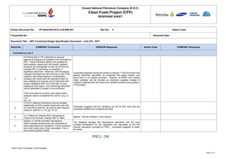
  • 1. Kuwait National Petroleum Company (K.S.C) Clean Fuels Project (CFP) RESPONSE SHEET Action Code: A-Accepted, N-Not accepted Page 1 of 1 Vendor Document No: VP-2025JV8J10121-216-B06-001 Rev No.: 4 Status Code- Transmittal No: Received Date: Document Title : APC Functional Design Specification Document – Unit 216 - DHT Serial No. COMPANY Comments VENDOR Response Action Code COMPANY Response Comment on rev.3 1. For Plants like U-116, inferential is required against all analyzers of qualities to be controlled by APC. These inferential needs to be updated by both analyzer values and LAB results. Analyzer locations are downstream to drier far off from all possible MV’s contributing to possibility of significant dead time. Moreover, with throughput changes this dead time will continue to vary. FDS needs to take these aspects in consideration. Analyzer like Cloud point are typically known for less reliability and requires use of inferential with proper validations both from LAB data, its own reading & other logics. Just mentioning inferential will be attempted in phase-2 is not sufficient. This is true also for all other units where direct analyzer value is considered for control. (e.g.: U- 115, Pg. 19) Honeywell explained during the review of revision 1 FDS document that getting inferential calculation for properties like gasoil sulphur and cloud point is not always accurate. However, as KNPC has insisted these variables will be included as inferential variables instead of analyzer measurement and have to be carefully studied during phase 2 of the project 2. CV16-21 (Bearing Vibrations) may be handled additionally at DCS complex loops with over-ride on Feed flow cutoff etc. as quick & safe measure. (Same is valid for U-115, pg. 14-15) Honeywell suggests that the vibrations are left at APC level and are constraint variables for increasing the feed. 3. 3.2.7 Maximum Reactor Bed 5 temperature: Typos in the formula: Change "Ma" to "Max" Agreed. Will be modified in next revision 4. Section 3.2 (Profit controller calculations) When average temperatures are calculated all temp tags should be considered .If temp indication turns bad simply drop it from calculation. This is the current practice in MAB. The weighted average bed temperature calculation and the input average temperature for the calculation are calculated as per the licensor calculation provided by PSCJ. Honeywell suggests to retain the same. PSCJ : OK
  • 2. Vendor Document Review Cover Sheet Kuwait National Petroleum Company (K.S.C.) Clean Fuels Project (CFP) Kuwait KNPC Contract No. CFP/EPC/0054-MAB1, Purchaser Job No. JI-2025 Mina Abdullah Refinery Purchase Order No. : 2025JV8J10121 Purchase Order Description : ADVANCE PROCESS CONTROL SYSTEM (PHASE - I) Vendor Name : HONEYWELL KUWAIT KSC Company Document Number : VP-2025JV8J10121-216-B06-001 Rev : 05 Vendor Document Number : VP-2025JV8J10121-216-B06-001 Rev : 05 Document Description / Title : APC FUNCTIONAL DESIGN SPECIFICATION DOCUMENT - UNIT-216 DIESEL HYDROTREATING UNIT Equipment Tag Numbers : PURCHASER APPROVAL STATUS Status Approval Code Code Description  A APPROVED WITHOUT COMMENT - WORK MAY PROCEED  B APPROVED WITH MINOR COMMENTS– WORK MAY PROCEED -REVISE AND RESUBMIT  C REVISE AND RESUBMIT – WORK MAY PROCEED SUBJECT TO INCORPORATION OF COMMENTS INDICATED  D APPROVAL NOT REQUIRED. INFORMATION ONLY. WORK MAY PROCEED  F AS-BUILT / ACCEPTED AS FINAL  R REJECTED - REVISE AND RESUBMIT. WORK MAY NOT PROCEED  V VOID (DOCUMENT HAS BEEN CANCELLED / DELETED) Purchaser’s review of this document does not relieve Vendor of the responsibility for correctness under the Purchase Order. Permission to proceed does not constitute acceptance of design, detail and calculations, test methods or materials developed or selected by the Vendor and does not relieve the Vendor from full compliance with the Purchase Order or any other obligations, nor detract from any of the Purchaser’s rights. Reviewing Engineer’s Full Name (IN BLOCK LETTERS), Sign and Date Name: Sign: Disp.: Date: 04.12.2017 sairaja S44279 S Khasnobis C&I 1 11.12.17
  • 3.
  • 4. Kuwait National Petroleum Company (K.S.C) Clean Fuels Project 2020 KNPC Contract No. CFP/EPC/0054-MAB1 PSCJ Job No. JI-2025 APC FDS Unit 216 – DIESEL HYDROTREATING UNIT VP-2025JV8J10121-216-B06-001 REV. 04, 26-NOV-2017 Page 2 of 21 Record Of Revisions Revision Page/Section Description 0 All Initial Release issued for comments 1 All Revised post FDS review meeting comments 2 All Revised post Rev. 1 comments 3 2/3 Revised post KNPC comments 4 All Revised post Rev. 3 comments List Of Holds Page/Section Description
  • 5. Kuwait National Petroleum Company (K.S.C) Clean Fuels Project 2020 KNPC Contract No. CFP/EPC/0054-MAB1 PSCJ Job No. JI-2025 APC FDS Unit 216 – DIESEL HYDROTREATING UNIT VP-2025JV8J10121-216-B06-001 REV. 04, 26-NOV-2017 Page 3 of 21 Table of Contents 1.0 INTRODUCTION.............................................................................................7 1.1 Scope ...........................................................................................................................7 1.2 References...................................................................................................................7 2.0 PROCESS OVERVIEW...................................................................................9 2.1 Process overview........................................................................................................9 2.2 Existing Controls Analysis ......................................................................................13 2.3 Operating Targets and Constraints.........................................................................14 3.0 RMPCT APPLICATIONS ..............................................................................15 3.1 Diesel Hydro Treater (U216).....................................................................................15 3.1.1 Objectives ......................................................................................................15 3.1.2 Strategies.......................................................................................................15 3.1.3 Profit Controller functional design..................................................................16 3.2 Profit Controller Calculations..................................................................................18 3.2.1 Waited Average Bed temperature 1 to 3 .......................................................18 3.2.2 Weighted Average Bed temperature 4 ..........................................................19 3.2.3 Maximum Reactor Bed 1 temperature...........................................................19 3.2.4 Maximum Reactor Bed 2 temperature...........................................................20 3.2.5 Maximum Reactor Bed 3 temperature...........................................................20 3.2.6 Maximum Reactor Bed 4 temperature...........................................................20 3.2.7 Maximum Reactor Bed 5 temperature...........................................................20 3.2.8 H2/HC ratio calculation ..................................................................................20 3.3 Inferential ...................................................................................................................21
  • 6. Kuwait National Petroleum Company (K.S.C) Clean Fuels Project 2020 KNPC Contract No. CFP/EPC/0054-MAB1 PSCJ Job No. JI-2025 APC FDS Unit 216 – DIESEL HYDROTREATING UNIT VP-2025JV8J10121-216-B06-001 REV. 04, 26-NOV-2017 Page 4 of 21 Figures No table of figures entries found.
  • 7. Kuwait National Petroleum Company (K.S.C) Clean Fuels Project 2020 KNPC Contract No. CFP/EPC/0054-MAB1 PSCJ Job No. JI-2025 APC FDS Unit 216 – DIESEL HYDROTREATING UNIT VP-2025JV8J10121-216-B06-001 REV. 04, 26-NOV-2017 Page 5 of 21 Tables Table 2-1 DHT Operating Targets and Constraints...............................................................14 Table 3-1 U216 DHT Profit Controller – Controlled variables (CV).....................................17 Table 3-2 U216 DHT Profit Controller – Manipulated variables (MV) .................................18 Table 3-3 DHT Profit Controller Profit Controller – Disturbance variables (DV)................18
  • 8. Kuwait National Petroleum Company (K.S.C) Clean Fuels Project 2020 KNPC Contract No. CFP/EPC/0054-MAB1 PSCJ Job No. JI-2025 APC FDS Unit 216 – DIESEL HYDROTREATING UNIT VP-2025JV8J10121-216-B06-001 REV. 04, 26-NOV-2017 Page 6 of 21 Abbreviations Symbol Detailed description APC Advanced Process Control DCS Distributed Control System PFS Process Flow Scheme PEFS Process Engineering Flow Scheme TAC Traditional Advanced Control
  • 9. Kuwait National Petroleum Company (K.S.C) Clean Fuels Project 2020 KNPC Contract No. CFP/EPC/0054-MAB1 PSCJ Job No. JI-2025 APC FDS Unit 216 – DIESEL HYDROTREATING UNIT VP-2025JV8J10121-216-B06-001 REV. 04, 26-NOV-2017 Page 7 of 21 1.0 INTRODUCTION Honeywell has been engaged by PSCJ for carrying out the Phase 1 activities of Advanced Process Control System implementation for the MAB refinery as a part of Kuwait National Petroleum Corporation (KNPC) Clean Fuels Project 2020 in Kuwait. As a part of phase 1 activity Honeywell has developed the APC Functional Design Specification (FDS) document. The following FDS documents are develop • Unit – 111 Crude Distillation Unit APC FDS • Unit – 114 Hydrocracker Unit APC FDS • Unit – 127 Continuous Cracker Reformer Unit APC FDS • Unit – 213 Vacuum Rerun Unit APC FDS • Unit – 214 Hydrocracker Unit APC FDS • Unit – 112 Atmospheric Residue Desulpharisation Unit APC FDS • Unit – 115 Kero Hydrotreater Unit APC FDS • Unit – 116 Diesel Hydrotreater Unit APC FDS • Unit – 117 Naptha Hydrotreater Unit APC FDS • Unit – 111 Crude Distillation Unit APC FDS • Unit – 212 Atmospheric Residue Desulpharisation Unit APC FDS • Unit – 216 Diesel Hydrotreater Unit APC FDS • System architecture and Interface FDS This document gives the Functional Design Specification document for Unit-112 Atmospheric Residue Desulphurisation Unit. This is based on the review of reference documents provided by the Contractor and Honeywell’s experience in implementing Advanced Process Control applications in such units. 1.1 Scope Scope of this document includes ‘Advanced Process Control” functional design on the following sections: • Describe the basic process of the unit • Summarize the DCS level control strategies for the unit as described in the PFS, PEFS and Control Narrative document • Specify the control strategies of APC for the unit • Specify the basic APC design for the unit summarizing the Controlled Variables (CV), Manipulated Variables (MV) and Disturbance Variables (DV) • Specify the inferential control variables used in the APC and possible inputs to the inferential • Specify the calculations used in the APC system and the inputs used in the calculations 1.2 References • Process Description - P6002MAB-216-10-4-B004 Rev E
  • 10. Kuwait National Petroleum Company (K.S.C) Clean Fuels Project 2020 KNPC Contract No. CFP/EPC/0054-MAB1 PSCJ Job No. JI-2025 APC FDS Unit 216 – DIESEL HYDROTREATING UNIT VP-2025JV8J10121-216-B06-001 REV. 04, 26-NOV-2017 Page 8 of 21 • Process Flow Scheme – P6002MAB-216-08-4-I101~107; I111~I113; I115; I201~I207; I211~I213; I215; I301~307; 311~313; 315; I401~I407; I411~I413; I415 Rev E • Process Engineering Flow Scheme – P6012MAB-216-08-4-J101~108; J110~J121; J123; J124~J128; J130~J143; J150~J153; J160~J166; J170~J195 Rev S2 • Process Control Narrative - P6012MAB.216-08R.26 Rev A4 • Project Specification – Advanced Process Control - P6000CFP.000.10.71.023 Rev D • Advanced Process Control Manual by Vendor - P6002MAB-216-10-4-B007 Rev E • Minutes of Meeting – FDS review Meeting – 19-21/12/16
  • 11. Kuwait National Petroleum Company (K.S.C) Clean Fuels Project 2020 KNPC Contract No. CFP/EPC/0054-MAB1 PSCJ Job No. JI-2025 APC FDS Unit 216 – DIESEL HYDROTREATING UNIT VP-2025JV8J10121-216-B06-001 REV. 04, 26-NOV-2017 Page 9 of 21 2.0 PROCESS OVERVIEW 2.1 Process overview The unit has a capacity of 73,000 BPSD and will be designed to process a blend of straight run (SR) gas oil from the Crude Distillation Units CDU-11 and CDU-111, the Delayed Coker Unit (DCU 20) and the Atmospheric Residue DeSulphurization Unit (ARDS-12 and ARDS-112/212). The hydrotreated diesel will meet the following criteria: • Meet low sulphur diesel product specifications of maximum 7 ppmwt sulphur. • Meet Cold Filter Plug Point (CFPP) specification of maximum 23 °F during summer operation and maximum –4 ° F during winter operation, however the unit will only be designed for a delta cloud point improvement of 10.8 ° F by means of catalytic dewaxing. The remainder will have to be achieved by cloud point depressant additives. • Achieve a (first) catalyst cycle length of 30 months • Meet poly aromatics specification of 5% max. All gas oil blend components entering the unit are collected in the Feed Collection Vessel (V- 216-107). The cold gas oil from storage is on flow control reset by the level control on the Feed Collection Vessel to provide a trim level control. The gas oil from the Feed Collection Vessel is boosted up to the Feed Surge Vessel (V-216-108) operating pressure by the Feed Collection Vessel Pump (P-216-101 A/B). The combined feed is passed through the Feed Filter (F-216- 101 A/B) to remove any foreign particulate matter, preheated in the Feed/Drier Bottoms Heat Exchanger (E-216-101 A/B) and is routed to the Feed Surge Vessel (V-216-108). The pre-heat is controlled by the temperature controller on the feed to the Feed Surge Vessel by manipulating the flow through the exchanger and the by-pass in the drier bottoms. The preheated gas oil feed is boosted up to reactor pressure by the Feed Charge Pump (P-216-102 A/B) and enters the reactor system under flow control. The gas oil feed is mixed with Treat Gas, which is rich in Hydrogen, and enters the Feed/Effluent Heat Exchanger (E-216-102 A-D), where the feed temperature is raised by exchanging heat with the reactor effluent. The Reactor Charge Heater (H-216-101), designed for firing of fuel gas only, is a forced / induced draft heater with air preheat which increases the inlet temperature to the level required for the reactions in the DHT Reactor (V-216-101) to commence. The heater can also operate on natural draft. The DHT Reactor consists of five (5) catalyst beds with a gas and liquid quench between beds 1-2 and liquid quenches between beds 2-3, beds 3-4 and beds 4-5 (the latter is normally no flow). The 1st bed is used for olefin saturation, desulphurization and denitrogenation reactions; the 2nd and 3rd bed are used for desulphurization and denitrogenation reactions. The 4th bed is used for dewaxing purposes. The 5th bed is a hydro-dearomatisation bed, to ensure the density and poly aromatics specs are met. The gas and liquid quenches are used to limit the temperature rise over the desulphurization beds. The gas quench is taken from the Recycle Gas Compressor under flow control and is a fixed value for each operating case. The liquid quench to beds 2, 3, 4 and 5 is liquid from the Hot High Pressure Separator (V-216-109) that is routed to the reactor by Quench Oil Pump (P-216-103 A/B), after cooling in Quench Oil Cooler (F.FAN-216-101 A/B) under temperature control. Depending on the unit operating mode the liquid quench to bed 4 (under temperature control) is used to switch the dewaxing catalyst ‘on’
  • 12. Kuwait National Petroleum Company (K.S.C) Clean Fuels Project 2020 KNPC Contract No. CFP/EPC/0054-MAB1 PSCJ Job No. JI-2025 APC FDS Unit 216 – DIESEL HYDROTREATING UNIT VP-2025JV8J10121-216-B06-001 REV. 04, 26-NOV-2017 Page 10 of 21 (winter mode) or ‘off’ (summer mode). The liquid quench to bed 5 is normally no flow and is installed in case extra conversion of poly aromatics is required. The cooled reactor effluent from Feed/Effluent Heat Exchanger (E-216-102 A-D) is fed into the Hot High Pressure Separator (V-216-109). The operating temperature of the Hot High Pressure Separator is controlled at 446 ° F by using the shell side by-pass valve around the Feed/Effluent Heat Exchangers. Part of the liquid from the Hot High Pressure Separator is sent back to DHT Reactor as quench oil using the Quench Oil Pump (P-216-103 A/B). The net liquid from Hot High Pressure Separator (V-216-109) is sent to the Product Stripper (V-216-102) where the H2S and gases are stripped from the gas oil. Vapours from the Hot High Pressure Separator are mixed with wash water from the Cold Low Pressure Separator (V-216-111) in the Hot High Pressure Separator Vapour / Wash Water Mixer (MX-216-101). The wash water injection is necessary to prevent corrosion by NH4HS and NH4Cl in the air cooler tubes. The mixture is then combined with wash oil (under flow control) from the Cold Low Pressure Separator (V-216-111) to absorb the heavy ends of the recycle gas and some H2S. The mixture is then cooled in the Reactor Effluent Air Cooler (F.FAN-216-102A-D). The three-phase mixture leaving the Reactor Effluent Air Cooler enters the Cold High Pressure Separator. The water from the Cold High Pressure Separator is fed to the sour water compartment in the Cold Low Pressure Separator (V-216-111) where light material is flashed off from the aqueous phase. Off gas from the Cold High Pressure Separator is then cooled in the CHPS off gas Trim Cooler (E-216-103) from where it is routed to the amine section. The Cold High Pressure Separator Hydrocarbon liquid leaves the separator under level control to the Cold Low Pressure Separator and subsequent work up section. Hydrocarbons from the Hot High Pressure Separator (V-216-109) are mixed with hydrocarbons from the Cold Low Pressure Separator (V-216-111) and are stripped, with intermediate pressure steam in the Product Stripper (V-216-102), at a steam rate of 3%wt on feed. The Stripper bottoms product is sent under level control to the Vacuum Drier (V-216-103). Overhead vapours from the Product Stripper are mixed with process wash water supplied by the Make- Up Wash Water Pump (P-216-107 A/B). This make-up wash water is injected before Product Stripper Overhead Condenser (F.FAN-216-103 A/B). The condensed stripper overheads leaving the Product Stripper Overhead Condenser (F.FAN-216-103 A/B) are sent to the Cold Low Pressure Separator (V-216-111) and are separated in a gas phase, a hydrocarbon phase and a water phase. The Wash Oil Pump (P-216-104) pumps part of the condensed hydrocarbons upstream of the Reactor Effluent Air Cooler (F.FAN-216-102A-D). The remaining hydrocarbons are recycled to the Product Stripper by the Stripper Recycle Pump (P-216-105 A/B). In case of upsets in the Vacuum Drier (V-216-103) it is possible to send out wild slops to battery limit. Under normal operating conditions this line is normally no flow. The water from the boot of the Cold Low Pressure Separator (V-216-111), consists of condensed stripping steam and make-up wash water, is routed as wash water to the Hot High Pressure Separator Vapour/ Wash Water Mixer (MX-216-101). The off-gas from the Cold Low Pressure Separator is sent to the MP off-gas header for further treatment. Water from the boot of the Cold High Pressure Separator (V-216-110) is fed to a separate sour water compartment of the Cold Low Pressure Separator and sent to battery limit for treatment together with excess water from the wash water compartment. The stripper bottoms is fed to the Vacuum Drier (V-216-103). In the Vacuum Drier the flash point and water spec are set. The overheads of the Vacuum Drier are cooled in the Drier Overhead Precondenser (F.FAN-216-104A-D) and Drier Overhead Trim Cooler (E-216-104 A/B), which condenses the bulk of the water and hydrocarbons. The condensed liquids are
  • 13. Kuwait National Petroleum Company (K.S.C) Clean Fuels Project 2020 KNPC Contract No. CFP/EPC/0054-MAB1 PSCJ Job No. JI-2025 APC FDS Unit 216 – DIESEL HYDROTREATING UNIT VP-2025JV8J10121-216-B06-001 REV. 04, 26-NOV-2017 Page 11 of 21 sent under gravity flow to the Drier Overhead Separator (V-216-118) where water and liquid hydrocarbons are separated. Water is routed by means of the Drier Sour Water Pump (P-216- 110 A/B) and combined with the sour water leaving the CLPS to battery limit for treatment. Hydrocarbons are routed by the Drier Recycle Pump (P-216-109 A/B) as much as possible to the Vacuum Drier to act as reflux, or to battery limit as slops together with hydrocarbons pumped by LRP Recycle Pump. The amount of slops to be rundown to battery limit is dictated by the flash point spec on the drier bottoms. Prior to entering the Vacuum Drier the reflux passes through the Drier Recycle Filter F-216-106 A/B to remove any foreign particulate matter which may plug the gravity distributor in the Vacuum Drier. The off-gas from the Drier Overhead Trim Cooler is routed to the Liquid Ring Pump (ME-216-103-P1 A/B) where water is used as liquid ring seal fluid. The compressed vapour-liquid mixture from the Liquid Ring Pump is discharged into the LRP Separator (ME-216-103-V1). The seal liquid (water) for Liquid Ring Pump is taken from the LRP Separator water boot and passed through the Seal Liquid Cooler (ME-216-103- E1) before entering the Liquid Ring Pump. Off-gas from the LRP Separator is sent to the Waste Gas Seal Vessel (V-216-112). This vessel prevents possible back flow of air/hydrocarbons to the vacuum system when the liquid ring pump fails. From there off-gas is sent via the Waste Gas KO Vessel (D-216-104) and Waste Gas Flame Arrestor (FA-216-101 A/B) to the Reactor Charge Heater (H-216-101). Alternatively the off-gas can be routed to atmosphere at safe location via Waste Gas to Atmosphere Flame Arrestor (FA-216-102 A/B) or to the flare when the oxygen concentration in the off-gas and flare header pressure is sufficiently low to allow this. A small water flow is routed/circulated over the Waste Gas Seal Vessel. The drier bottoms (finished diesel product) is pumped by Diesel Product Pump (P-216-108 A/B) through the Feed/Drier Bottoms Heat Exchanger (E-216-101 A/B) and Diesel Product Air Cooler (F.FAN-216-105A-F) followed by the Diesel Product Trim Cooler (E-216-105) to battery limit. The Diesel product flow control is reset by the level controller at the bottom of the Vacuum Drier. Lubricity additive is added by means of Lubricity Injection Package (ME-216-104) to the finished Diesel product to increase the lubricating properties of the diesel. A cloud point depressant additive is also added to bring the diesel product within specification for cold flow properties. Cold Low Pressure Separator off-gas is cooled in the CLPS Offgas Cooler (E-216-107) to approximately 122 ° F. Subsequently it is routed to the LP Amine Absorber KO Vessel (D-216- 101) to remove liquids. The gas is then routed to the bottom of LP Amine Absorber (D-216-105) where it combines with flashed gases from the rich amine from HP Amine Absorber (V-216- 104). In the LP Amine Absorber (V-216-105) the gas is counter currently contacted with a 45 wt% MDEA solution. The treated gas, with an H2S concentration of no greater than 100 ppm vol, is then routed to Gas Handling in the Hydrogen Unit on flow control or to the refinery fuel gas system on backpressure control. Lean MDEA from the Amine Regenerator is pumped through the Amine Lean/Rich Heat Exchanger, the Lean Amine Cooler and Lean Amine Trim Cooler (F.FAN-216-106, E-216-108 A-C and E-216-106 respectively) under flow control to the LP Amine Absorber. Rich amine leaving the LP Absorber is sent under level control to the Amine Regenerator (V- 216-106) with the control valve situated downstream of the Amine Lean/Rich Heat Exchanger (E-216-108 A-C) to minimise flashing in the heat exchanger. The Lean Amine leaving the Amine
  • 14. Kuwait National Petroleum Company (K.S.C) Clean Fuels Project 2020 KNPC Contract No. CFP/EPC/0054-MAB1 PSCJ Job No. JI-2025 APC FDS Unit 216 – DIESEL HYDROTREATING UNIT VP-2025JV8J10121-216-B06-001 REV. 04, 26-NOV-2017 Page 12 of 21 Regenerator is recycled via the Lean/Rich Heat Exchanger, the Lean Amine Cooler and the Lean Amine Trim Cooler back to the HP and LP Absorbers. The H2S rich overheads of the Amine Regenerator are cooled in the Regenerator Overhead Condenser (F.FAN-216-107). The liquid/vapour stream is separated in the Regenerator Reflux Vessel (V-216-114). The condensed liquid is sent as reflux back to the Amine Regenerator column by the Regenerator Reflux Pump (P-216-116 A/B). If ammonia is present in the feed gases to the absorbers it will be absorbed in the aqueous amine solution. The ammonia will then be released from the rich solvent in the regenerator and it will partly end up in the H2S rich acid gas. The ammonia will react with H2S to form ammonium hydrosulphide (NH4HS), which is corrosive in the presence of water. Bleeding of reflux water to the existing Sour Water Stripper Unit will be required to avoid accumulation of ammonium hydrosulphide. To control the water content of the solvent, make-up water is added to the reflux loop to maintain the water balance.The acid gas leaving the Regenerator Reflux Vessel is routed to the Sulphur Recovery Unit. If required this stream can also be routed to the acid gas flare. Suspended solids are considered to be a major cause of foaming in absorbers and regenerators. A slipstream of the circulating lean solvent (10% of the total solvent circulation) is passed through the Amine Mechanical Filter (F-216-102 A/B) to control the suspended solids concentration in the solvent. After mechanical filtration, half of the filtered stream (5% of the total solvent circulation) is passed through an Activated Carbon Filter (F-216-103) to remove surface-active contaminants plus Carbon After Filter (F-216-104) to remove carbon fines. A constant pressure drop (approximately 29 psi) across the three filters is maintained by means of a pressure differential control valve that is located in the main solvent line to assure constant flow in the whole system. A flow controller downstream the Amine Mechanical Filter (F-216-102 A/B) controls the 10% of the total rate through this filter. Subsequently, a secondary slipstream diverts 5% of the total solvent circulation to the carbon filter. A constant pressure drop (approximately 14.5 psi) is maintained across the Activated Carbon Filter (F-216-103) and Carbon After Filter (F-216-104) by means of a pressure differential control valve that is located in the secondary slipstream to assure constant flow in the secondary slipstream. A flow controller downstream F-216-103 and F-216-104 controls the 5% of the total rate through these filters. The Amine unit is equipped with a closed drain system to collect the solvent from the maintenance and operational drains of each piece of equipment. The drain system contains an Amine Drain Vessel (V-216-113), which is situated below ground level. This vessel is designed to separate skimmed and entrained hydrocarbons from the solvent. During routine operations the Amine Drain Vessel (V-216-113) also receives and accumulates the contents of the filters before filter change out. In normal operation the oil free solvent is filtered in the Storage Return Filter (F-216-105) before being recycled back to the Regenerator column feed inlet by pump P- 216-120 A/S under flow control. The solvent is kept under a fuel gas blanket to prevent the ingress of oxygen. Separated oil is pumped out from the vessel to the oil slops system by pump P-216-121. The Amine Drain Vessel (V-216-113) is designed to receive and transfer fresh amine as makeup to the amine system. The Amine Solvent Storage Tank (TK-216-102) is sized for the storage of a whole unit inventory during maintenance or inspection. If the unit has to be emptied, solvent has to be regenerated prior to routing it to the Amine Solvent Storage Tank to avoid vaporization of H2S. A line downstream of the Lean Amine Trim Cooler (E-216-106) shall be provided to transfer the inventory after stripping it out.
  • 15. Kuwait National Petroleum Company (K.S.C) Clean Fuels Project 2020 KNPC Contract No. CFP/EPC/0054-MAB1 PSCJ Job No. JI-2025 APC FDS Unit 216 – DIESEL HYDROTREATING UNIT VP-2025JV8J10121-216-B06-001 REV. 04, 26-NOV-2017 Page 13 of 21 Initially, solvent comes directly from the unit through a dedicated line located downstream E- 216-106. Subsequently, the remaining solvent can be drained into this vessel and pumped to the Solvent Storage Tank (TK-216-102) using Drain Solvent Pump (P-216-120 A/S). A fuel gas blanketing system has been provided to prevent ingress of oxygen. An Amine storage pump P- 216-118 and flow controller have been provided to regulate and transfer the amine back to the Amine Regenerator sump. 2.2 Existing Controls Analysis The following DCS level controls are available for the unit. Unit feed collection drum level control Feed collection drum, V-216-107, level LC1078 is controlled by cascading to FC1155 (combined hot rundown flow) or FC1120 (cold diesel from storage). HS-1043 allows selection of the control signal to the slave controllers FC-1120 (cold SR Diesel from storage at normal operation) or FC-1155 (NNF, used for cold start up). The DCS level control would be sufficient to take control the collection drum level. Pre-heat temperature control Pre-heat temperature TC1013 is a split range controller and is maintained by sending outputs to valves TV-1013A (through exchanger E-216-101 A/B) and TV-1013B (exchanger bypass ). This pre-heat temperature will be sufficient to control the feed temperature to furnace Reactor Charge Heater Control Heater (H-216-101) outlet temperature TC1068 is controlled fuel gas flow FC1054 (which manipulates fuel gas pressure PC1141B) and air flow FC1056 (which is reset by air/fuel ratio manual adjuster HC-1047). This control uses low selection FY1060F and high selection FY1060G so that when increasing fuel demand air increases and when decreasing fuel demand fuel gas flow decreases The furnace control is provided in DCS and expected to work well, however, effectiveness of furnace control will be looked again during phase 2 of the project (after site implementation) and if necessary a dedicated profit controller for furnace control may be implemented to achieve both control and optimization. Stripper Column Steam Control Stripper column steam is adjusted by feed forward control FFC1035 which manipulates steam flow based on feed forward input from feed flow FC1025. This ratio control at DCS level will be manipulated by MVPC Vacuum Drier Level Vacuum drier level is controlled by diesel product rundown flow FC1042. This level control will be at DCS level only
  • 16. Kuwait National Petroleum Company (K.S.C) Clean Fuels Project 2020 KNPC Contract No. CFP/EPC/0054-MAB1 PSCJ Job No. JI-2025 APC FDS Unit 216 – DIESEL HYDROTREATING UNIT VP-2025JV8J10121-216-B06-001 REV. 04, 26-NOV-2017 Page 14 of 21 2.3 Operating Targets and Constraints The operating targets include defined operating targets for the unit (e.g. due to equipment limit, product specification, etc.), as well as indirect operating targets inferred from historical plant data (e.g. reactor bed temperatures, etc.). Since there is no history, only operating targets as outlined in the specifications manual are taken here. The targets and specifications pertaining to this unit are listed below Table 2-1 DHT Operating Targets and Constraints1 Description Operating Target Low Limit High Limit Recycle compressor Max axial vibration 0.381 mm Recycle compressor Max horizontal vibration 53 ㎛ Recycle compressor Max axial vibration 53 ㎛ Recycle compressor turbine Max axial vibration 0.381 mm Recycle compressor turbine Max horizontal vibration 53 ㎛ Recycle compressor turbine Max axial vibration 53 ㎛ Reactor Bed 1 Maximum temperature 380 ⁰C (716 ⁰F) Reactor Bed 2 Maximum temperature 380 ⁰C (716 ⁰F) Reactor Bed 3 Maximum temperature 380 ⁰C (716 ⁰F) Reactor Bed 4 Maximum temperature 380 ⁰C (716 ⁰F) Reactor Bed 5 Maximum temperature (calculated) 380 ⁰C (716 ⁰F) Diesel product sulphur 7 ppmw Diesel product Cloud point March- November (Transition) : 0 ⁰C (32 ⁰F) April – October (Summer) : 4 ⁰C (39.2 ⁰F) 1 Constraints limits given in Table 2.1 are based on the design data. Actual constraints limit, especially the operation targets and bounds, may vary from design data. It will be updated in phase 2, after seeing the actual plant operation and constraints
  • 17. Kuwait National Petroleum Company (K.S.C) Clean Fuels Project 2020 KNPC Contract No. CFP/EPC/0054-MAB1 PSCJ Job No. JI-2025 APC FDS Unit 216 – DIESEL HYDROTREATING UNIT VP-2025JV8J10121-216-B06-001 REV. 04, 26-NOV-2017 Page 15 of 21 Description Operating Target Low Limit High Limit December – Feb (Winter) : -7 ⁰C (19.4 ⁰F) Diesel product flash point 66⁰C (150.8 ⁰F) Equipment constraints may be persistent (e.g. compressor vibration) or temporary (e.g. bed temperatures). It is important that the advanced control design incorporate variables that allow these constraints to be respected. It is also important to understand the status of the constraints and when/if they will be removed. This information can be used to determine the best schedule for plant testing. It is desirable to develop process models that represent the unit as closely as possible. 3.0 RMPCT APPLICATIONS 3.1 Diesel Hydro Treater (U216) 3.1.1 Objectives Objectives for APC implementation in Diesel Hydro treater are: • Maintain Sulphur in the treated product below and near the maximum limit (7 ppm) • Maintain Cloud point in the treated product below and near the minimum limit for Summer and Winter specifications • Maintain the poly aromatics in the treated product below and near the maximum limit (5%)) • Maintain the flash point in the treated product above and near the minimum limit • Maximise catalyst cycle length 3.1.2 Strategies A single Profit controller across the DHT unit will be used to achieve the objectives. To control the sulphur in the product it is essential to maintain consistent WABT (Weighted Average Bed Temperature). As the hydro-desulphurisation reactions occurs in the top three beds, the WABT across bed 1 to 3 will be controlled. Reactor inlet temperature will be used to control WABT The Cloud point in the product will be maintained by controlling the WABT across bed 4 where de-waxing reactions taking place. The bed temperature control will be used for controlling the WABT Poly aromatics content is controlled using the bed 5 temperature control. Also the H2/HC ratio will be used as an handle Flash in the finished product will be controlled by manipulating the steam/product ratio in the product stripper
  • 18. Kuwait National Petroleum Company (K.S.C) Clean Fuels Project 2020 KNPC Contract No. CFP/EPC/0054-MAB1 PSCJ Job No. JI-2025 APC FDS Unit 216 – DIESEL HYDROTREATING UNIT VP-2025JV8J10121-216-B06-001 REV. 04, 26-NOV-2017 Page 16 of 21 The following are constraints will be considered when maximising the capacity of the unit • Recycle gas compressor turbine speed / steam to governor valve opening • Make-up gas hydrogen valve opening 3.1.3 Profit Controller functional design The following tables give the proposed CVs, MVs and DVs for Diesel Hydrotreater Profit Control application. CV Tag Description Comments 1. 216GO_SUL Diesel product Sulphur This CV is expected to be controlled by manipulating reactor inlet temperature. 2. 216GO_CLOUD Diesel product Cloud point This CV is expected to be controlled by manipulating reactor bed 4 temperature. 3. 216GO_FLASH Diesel product flash point This CV is expected to be controlled by manipulating stripper steam to product ratio 4. 216WABT13.PV Weighted average bed temperature from bed 1 to 3 This CV is expected to be controlled by manipulating reactor I/L temperature 5. 216WABT4.PV Weighted average bed temperature from bed 4 This CV is expected to be controlled by bed 4 temperature 6. 216BED1_TMAX. PV Reactor Bed 1 Maximum temperature (calculated) This CV is calculated from maximum of I/L and O/L bed 1 temperatures. This CV is expected to be controlled by manipulated bed 1 temperature 7. 216BED2_TMAX. PV Reactor Bed 2 Maximum temperature (calculated) This CV is calculated from maximum of I/L and O/L bed 2 temperatures. This CV is expected to be controlled by manipulated bed 2 temperature 8. 216BED3_TMAX. PV Reactor Bed 3 Maximum temperature (calculated) This CV is calculated from maximum of I/L and O/L bed 3 temperatures. This CV is expected to be controlled by manipulated bed 3 temperature 9. 216BED4_TMAX. PV Reactor Bed 4 Maximum temperature (calculated) This CV is calculated from maximum of I/L and O/L bed 4 temperatures. This CV is expected to be controlled by manipulated bed 4 temperature 10. 216BED5_TMAX. PV Reactor Bed 5 Maximum temperature (calculated) This CV is calculated from maximum of I/L and O/L bed 5 temperatures. This CV is expected to be controlled by manipulated bed 5 temperature 11. 216CA101.PV Reactor H2/HC ratio This CV is calculated from treated recycle gas and feed flow to reactor This CV is expected to be controlled by manipulating Cold High Pressure separator 12. 216CA102.PV H2 purity in recycle gas This CV is expected to be controlled by manipulating bleed flow
  • 19. Kuwait National Petroleum Company (K.S.C) Clean Fuels Project 2020 KNPC Contract No. CFP/EPC/0054-MAB1 PSCJ Job No. JI-2025 APC FDS Unit 216 – DIESEL HYDROTREATING UNIT VP-2025JV8J10121-216-B06-001 REV. 04, 26-NOV-2017 Page 17 of 21 CV Tag Description Comments 13. 216AI1025.PV H2S in recycle gas This CV is expected to be controlled by manipulating bleed flow 14. 216SI1713B.PV Recycle gas compressor turbine speed This is a constraint CV This CV is expected to be controlled by manipulating feed flow 15. 216PC1076.OP Cold high pressure separator pressure This is a constraint CV This CV is expected to be controlled by manipulating feed flow 16. C-216- 101_MAX_VZI.PV C-216-101 Max axial vibration This is a constraint CV for maximising the feed 17. C-216- 101_MAX_VXI.PV C-216-101 Max Journal bearing vibration - X This is a constraint CV for maximising the feed 18. C-216- 101_MAX_VYI.PV C-216-101 Max Journal bearing vibration - Y This is a constraint CV for maximising the feed 19. C-216-101- T_MAX_VZI.PV C-216-101-T Max axial vibration This is a constraint CV for maximising the feed 20. C-216-101- T_MAX_VXI.PV C-216-101-T Max Journal bearing vibration - X This is a constraint CV for maximising the feed 21. C-216-101- T_MAX_VYI.PV C-216-101-T Max Journal bearing vibration - Y This is a constraint CV for maximising the feed Table 3-1 U216 DHT Profit Controller – Controlled variables (CV) MV Tag Description Comments 1. 216FC1007.SP Reactor Hydrocarbon flow This MV will be used for relieving recycle compressor turbine and make-up hydrogen valve constraints 2. 216SC1714B.SP Recycle gas compressor speed This MV will be used for controlling the H2/HC ratio 3. 216TC1068.SP Reactor I/L temperature control This MV will be used for controlling bed 1 to 3 WABT, product sulphur CVs 4. 216TC1079.SP Reactor Bed 4 temperature control This MV will be used for controlling product cloud point CV and maximum bed 4 temperature constraint 5. 216TC1076.SP Reactor Bed 2 liquid quench control This MV will be used for controlling maximum bed 2 temperature constraint 6. 216TC1239.SP Reactor Bed 3 liquid quench control This MV will be used for controlling maximum bed 3 temperature constraint
  • 20. Kuwait National Petroleum Company (K.S.C) Clean Fuels Project 2020 KNPC Contract No. CFP/EPC/0054-MAB1 PSCJ Job No. JI-2025 APC FDS Unit 216 – DIESEL HYDROTREATING UNIT VP-2025JV8J10121-216-B06-001 REV. 04, 26-NOV-2017 Page 18 of 21 MV Tag Description Comments 7. 216TC1082.SP Reactor Bed 5 liquid quench control This MV will be used for controlling maximum bed 5 temperature constraint 8. 216HC1235.OP Bleed valve on recycle line This MV will be used for controlling the H2S content in recycle gas 9. 216PC1085.SP Product stripper pressure This MV is minimized 10. 216FFC1035.SP Product stripper bottom steam to product ratio This MV will be used for controlling product flash point CV Table 3-2 U216 DHT Profit Controller – Manipulated variables (MV) DV Tag Description Comments 1. 216FC1016.SP Reactor bed 1 gas quench flow 2. 216TOTCOLDFD Total cold feed to feed collection vessel This DV is calculated by summing the cold feeds 216FC1120 and 216FC1155 3. 216FEED_TOT_S Calculated total sulphur in feed Table 3-3 DHT Profit Controller Profit Controller – Disturbance variables (DV) 3.2 Profit Controller Calculations The calculations used in the APC application are given below 3.2.1 Waited Average Bed temperature 1 to 3 The weighted average bed temperature from bed 1 to 3 is calculated as follows 21613. WABTbed 1 WABTbed 2 WABTbed 3 / 3 Where, WABTbed 1 = Weighted average bed 1 temperature WABTbed 2 = Weighted average bed 2 temperature WABTbed 3 = Weighted average bed 3 temperature 1 wtfract_DCU x 1/5 x Tin, bed 1 4/5 x Tout, bed 1 1 - wtfrac DCU x 1/3 x Tin, bed 1 2/3 x Tout, bed 1 /012340 567 209:1603. 209:1703. 2169:1007. ∗ 869/859 Where Wtfract_DCU = weight fraction of coker material in combined DHT feed
  • 21. Kuwait National Petroleum Company (K.S.C) Clean Fuels Project 2020 KNPC Contract No. CFP/EPC/0054-MAB1 PSCJ Job No. JI-2025 APC FDS Unit 216 – DIESEL HYDROTREATING UNIT VP-2025JV8J10121-216-B06-001 REV. 04, 26-NOV-2017 Page 19 of 21 Tin = Bed 1 I/L temperature (Average of TI1073 A~J) Tout = Bed 1 O/L temperature (Average of TI1074 A~J) 2 1/3 x Tin, bed 2 2/3 x Tout, bed 2 Where Tin = Bed 2 I/L temperature (Average of TI1076 A~F) Tout = Bed 2 O/L temperature (Average of TI1077 A~J) 3 1/3 x Tin, bed 3 2/3 x Tout, bed 3 Where Tin = Bed 3 I/L temperature (Average of TI1239 A~J) Tout = Bed 3 O/L temperature (Average of TI1255 A~J) Note: • When Average temperatures are calculated the maximum and minimum indication of the lot is not included and the average is calculated from remaining indications • If temperature indication turns BAD last good value is used in calculation 3.2.2 Weighted Average Bed temperature 4 The weighted average bed temperature from bed 1 to 3 is calculated as follows 2164. Tin, bed 4 Tout, bed 4 / 2 Where, Tin Bed 4 I/L temperature Average of TI1079 A~J Tout Bed 4 O/L temperature Average of TI1080 A~J Note: • When Average temperatures are calculated the maximum and minimum indication of the lot is not included and the average is calculated from remaining indications • If temperature indication turns BAD last good value is used in calculation 3.2.3 Maximum Reactor Bed 1 temperature This calculated from the maximum of reactor I/L and O/L temperatures 216H51_IJ. I3K 216:1073 ~L, 216:1074~L Where, 216TI1073A~J = Bed1 I/L temperatures 216TI1074A~J = Bed2 O/L temperatures
  • 22. Kuwait National Petroleum Company (K.S.C) Clean Fuels Project 2020 KNPC Contract No. CFP/EPC/0054-MAB1 PSCJ Job No. JI-2025 APC FDS Unit 216 – DIESEL HYDROTREATING UNIT VP-2025JV8J10121-216-B06-001 REV. 04, 26-NOV-2017 Page 20 of 21 3.2.4 Maximum Reactor Bed 2 temperature This calculated from the maximum of reactor I/L and O/L temperatures 216H52_IJ. I3K 216:1076 ~L, 216:1077~L Where, 216TI1076A~J = Bed1 I/L temperatures 216TI1077A~J = Bed2 O/L temperatures 3.2.5 Maximum Reactor Bed 3 temperature This calculated from the maximum of reactor I/L and O/L temperatures 216H53_IJ. I3K 216:1239 ~L, 216:1255~L Where, 216TI1239A~J = Bed1 I/L temperatures 216TI1255A~J = Bed2 O/L temperatures 3.2.6 Maximum Reactor Bed 4 temperature This calculated from the maximum of reactor I/L and O/L temperatures 216H54_IJ. I3K 216:1079 ~L, 216:1080~L Where, 216TI1079A~J = Bed1 I/L temperatures 216TI1080A~J = Bed2 O/L temperatures 3.2.7 Maximum Reactor Bed 5 temperature This calculated from the maximum of reactor I/L and O/L temperatures 216H55_IJ. I3K 216:1082 ~L, 216:1220~9 Where, 216TI1082A~J = Bed1 I/L temperatures 216TI1220A~F = Bed2 O/L temperatures 3.2.8 H2/HC ratio calculation This calculated from the H2 in treated recycle gas and feed flow 2166101. 9J1129. ∗ M2 N2O0P ∗ 1.699 9:1007. ∗ 0.23 Where, 216CA101.PV = H2/HC ratio FX1129.PV = compensated recycle flow (with FI1129, TI1129 and PI1220 as inputs) FI1007.PV = feed rate to the unit H2 Purity = 216CA102.PV (which is a linear function of molecular weight of recycle gas)
  • 23. Kuwait National Petroleum Company (K.S.C) Clean Fuels Project 2020 KNPC Contract No. CFP/EPC/0054-MAB1 PSCJ Job No. JI-2025 APC FDS Unit 216 – DIESEL HYDROTREATING UNIT VP-2025JV8J10121-216-B06-001 REV. 04, 26-NOV-2017 Page 21 of 21 3.3 Inferential The inferential calculations are designed to overcome one of the following reasons while implementing MVPC controllers. • Measurement unavailability or unreliable measurement • Low frequency of measurement (Sampling delay in case of analyzers) • Long dead time and/or dynamics Depending on the data availability, one of the various modelling methods are chosen for inferential. When enough good data, covering entire gamut of operation, is available then statistical regression methods are chosen. When less data is available, mix of analytical – empirical methods are chosen. When there is no data availability, complete analytical method based on first principal technique are chosen. In case of first principle method based inferential calculations, it is important to calibrate the model to consider the measurement errors. All the inferential in unit 216 are to be developed using statistical regression methods. Since there are no data available at this point of time, detailed model and calculations will be done in phase 2. For the implementation of APC in this unit, following inferential are to be developed. • 216GO_SUL – Gasoil product sulphur • 216GO_CLOUD – Gasoil product cloud point • 216GO_FLASH – Gasoil flash point outlet of product stripper • 216CA102.PV – H2 purity in recycle gas is inferred using recycle molecular weight analyzer input (216AI1007) For Product sulphur and pour point qualities, inferentials are considered as CVs. Retaining these inferentials instead of direct analyzer measurement has to be decided based on the accuracy of inferential models during the next phase of the project.