
Recommended
More Related Content
What's hot
What's hot (20)
Similar to Power system earthing.pptx
Similar to Power system earthing.pptx (20)
Recently uploaded
Recently uploaded (20)
Power system earthing.pptx
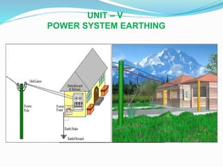
- 1. UNIT – V POWER SYSTEM EARTHING
- 2. POWER SYSTEM EARTHING Power system earthing: Objectives, definitions, Tolerable limits of body currents, Soil resistivity, Earth resistance, Tolerable Step and touch voltages, Neutral earthing, Ungrounded and effectively grounded system, Resistance, Reactance, Arc suppression coil earthing and grounding transformers. Arcing grounds, protection against arcing grounds.
- 3. EARTHING &GROUNDING Earthing and grounding are similar terms. Still, these are having many differences. The main difference between earthing and grounding is that the earthing refers that the circuit is physically connected to the ground with Zero Volt Potential. But, grounding refers that the circuit is not physically connected to ground, but still has zero potential. One other important difference between earthing and grounding is that in grounding, the current-carrying part is connected to the ground. But, in earthing the non-current carrying parts are connected to the ground.
- 4. What is Earthing? Earthing is the process of protecting against the unwarranted spikes and bouts of electricity which may cause damage to appliances as well as life. Thus, we need to understand the concept of electric potential. Earthing means the connection of non-current carrying parts of the equipment to the earth. During the occurrence of any fault in the system, the potential of the non-current part of the equipment raises. And, if anyone touches the body of the equipment, then they may get shocked. This earthing discharges the leakage of the current to the earth. In this way, we may avoid electric shock. It also protects our home appliances from lightning strokes. To achieve the earthing, we need to connect the parts of the installation to the earth by using the earth conductor or electrode. It is being placed in the soil at some distance below the ground level.
- 5. What is Grounding? It is similar to the earthing, for doing insulation of electrical devices against accidental currents. The main live wire is connected to the power supply to connect the appliance, but the other portion of the wire is led under the earth. In the grounding process, the current-carrying part is directly connected to the ground. In this way, grounding provides the return path for the leakage current and as a result, it protects the power system equipment from damage. When the fault occurs in the equipment, the current in all the three phases of the equipment becomes unbalance. The grounding provides great safety to the equipment and improves service reliability.
- 8. The objective of earthing are: 1.To allow sufficient current to flow safely for proper operation of protective devices. 2.To limit over voltages between neutral and ground and between line and ground. 3.To suppress dangerous high potential gradients.
- 9. Earthing can be divided into two ways 1.Neutral earthing 2.Equipment earthing. Neutral earthing deals with earthing of system neutral to ensure safety of personnel and protection against lighting. Equipment earthing deals with earthing of non- current carrying parts of equipment to ensure safety of personnel and protection against lighting.
- 10. Earthing can be done by electrically connecting the respective parts in the installation to some system of electrical conductors or electrodes placed near the soil or below the ground level. The earthing mat or electrode under the ground level have flat iron riser through which all the non-current- carrying metallic parts of the equipment are connected.
- 11. When the fault occurs the fault current from the equipment flows through the earthing system to the earth and thereby protect the equipment from the fault current. At the time of the fault, the earth mat conductors rise to the voltage which is equal to the resistance of the earth mat multiplied by a ground fault.
- 12. The contacting assembly is called earthing. The metallic conductors connecting the parts of the installation with the earthing are called electrical connection. The earthing and the earthing connection together called the earthing system
- 13. DEFINITIONS: EARTH ELECTRODE: A rod , pipe, plate or an array of conductors, embedded in earth horizontally or vertically. In distribution system the earth electrode consists of a rod about 1m long , driven vertically into ground. For substations an elaborate earthing system known as earth grid or earth mat is used. EARTH CURRENT: The current dissipated by earth electrode into the ground.
- 14. RESISTANCE OF EARTH ELECTRODE: The resistance offered by the earth electrode to the flow of current into the ground. The resistance is not the ohmic resistance of the electrode but represents the resistance of the mass of earth surrounding the earth electrode. Numerically it is equal to the ratio of potential of earth electrode with respect to remote point, to the current dissipated by it.
- 15. STEP POTENTIAL: The potential difference shunted by a human body between two accessible points on the ground separated by the distance of one pace assumed to be equal to 1m. TOUCH POTENTIAL: The potential difference between a point on the ground and a point on an object likely to carry fault current (e.g Frame of equipment) and which can be touched by a person.
- 16. Step and touch voltages
- 18. MESH POTENTIAL: The maximum potential within a mesh of the grid. TRANSFERRED POTENTIAL: A special case of touch potential where a potential is transferred into or out of the substation.
- 19. TOLERABLE LIMITS OF BODY CURRENTS: The effect of electric current passing through vital organs of the body depends on 1.Magnitude of current 2.Duration of current 3.Frequency of current. The most dangerous consequences is a heart condition known as ventricular fibrillation which results in stoppage of blood circulation.
- 20. (a)Effect of magnitude of current : The threshold of perception is a current of 1mA. Current in the range of 1-6 mA are known as “Let to go current” because these currents, though unpleasant, do not impair the ability of a person, holding an energised object, to release it. Currents in the range 9-25 mA may be painful and impair the ability to release energised object. Still higher current makes breathing difficult.
- 21. However , if the current is less than about 60 mA, the effect are not permanent and disappear when current is interrupted. Currents higher than 60 mA ,the effects are not permanent and disappear when current is interrupted. Currents higher than 60 mA may lead to ventricular fibrillation, injury and death.
- 22. (b)Effect of duration of current : The magnitude of 50Hz tolerable current is related to duration. According to tests reported by Dalziel, 99.5% of persons of 50Kg weight can safely withstand the current given by equation. IB = 0.116/√t ------- 1 where IB is RMS value of body current in amperes and t is the time in seconds. If the weight of body is 70Kgs. IB = 0.157 /√t ------- 2 are valid for 0.03<t<3 sec.
- 23. (c)Effect of frequency: The tolerable currents mentioned above for 50-60 Hz. It has been found that human body can tolerance about 5times higher direct hit current. At high frequencies (3000-10kHz) still higher currents can be tolerated.
- 24. SOIL RESISTIVITY: The resistivity of soil depends on the following factors SOIL TYPE: The type of soil governs the resistivity to large extent. Some typical values are Sea water 2.5 Ω -m, Tap water 20 Ω -m, Clay 50 Ω -m, Sand 2000 Ω -m, dry concrete 10000 Ω -m, rock 10000 Ω -m.
- 25. MOISTURE CONTENT: Electrical conduction in soil is electrolytic. Soil resistivity decreases with increase in moisture content as shown in Fig 1. However when the moisture is more than 20% the change in resistivity is negligible. The amount of water which a soil can absorb depends on soil type, grain size and compactness.
- 27. TEMPERATURE: When temperature is more than zero degrees , its effect on soil resistivity is negligible. At zero degrees , water in the soil starts freezing and resistivity increases. SALT CONTENT: The composition and amount of soluble salts also affect resistivity considerably as shown in Fig2.
- 28. MAGNITUDE OF CURRENT: If the value of current being dissipated by the soil is high, it may cause significant drying of soil and increase in its resistivity. The soil resistivity at a particular location also changes with depth. Generally the lower layers of soil have greater moisture content and lower resistivity. However , if the lower layer contains hard , rocky soil resistivity may increase with depth.
- 31. NEUTRAL EARTHING or GROUNDING The process of connecting neutral point of 3-phase system to earth directly or through some circuit element (e.g resistance, reactance) is called neutral earthing . The neutral earthing doesn’t have any influence on the operation of a 3-phase system under balanced steady state conditions. However, the voltage and currents during ground fault conditions are greatly effects. The neutral grounding is an important aspect of power system design because the performance of the system regarding short circuits, stability, protection, etc., is greatly affected by the condition of the neutral.
- 32. Neutral grounding provides protection to personnel and equipment. It is because during earth fault, the current path is completed through the earth neutral and the protective devices(eg fuses) operate to isolate the faulty conductor from the rest of the system this is illustrated in the figure below
- 33. A three phase system can be operated in two possible ways With ungrounded neutral With a grounded neutral
- 34. Advantages of neutral grounding 1.Voltages of the healthy phases do not exceed line-to- ground voltages. i.e they remain nearly constant. 2The high voltages (Surge )due to arcing grounds are eliminated. 3.The over voltages due to lightning discharged to earth. 4.The Protective relays can be used to provide protection against earth faults. 5.It provides greater safety to personnel and equipment. 6.It provides improved service reliability 7.Operating and maintenance expenditure are reduced
- 35. Isolated Neutral or Ungrounded System In an ungrounded neutral system, the neutral is not connected to the grounded. In other words, the neutral is isolated from the ground. Therefore, this system is also known the isolated neutral system or free neutral system shown in the figure below. The main feature of ungrounded neutral is its ability to clear ground fault without interruption.
- 37. Fig shows ungrounded neutral system. The line conductors have capacitance b/n one another and to ground. The former are delta connected while the later are star connected. The delta connected capacitances are little effect on the grounding characteristics of the system(i.e these capacitances do not effect the earth circuit) and therefore can be neglected , and the circuit then reduces to the one shown in fig below.
- 39. Circuit behavior under normal conditions: The behavior of ungrounded neutral system under normal conditions (i.e. under steady state and balanced conditions). The line is assumed to be perfectly transposed so that each conductor has the same capacitance to ground. Therefore, CR=CY=CB=C (say). Since the phase voltages VRN,VYN and VBN have the same magnitude (of course, displaced 120° from one another), the capacitive currents IR, Iy and IB will have the same value i.e. where Vph = Phase voltage (i.e. line-to-neutral voltage) xc = Capacitive reactance of the line to ground.
- 41. The capacitive currents IR, Iy and IB lead their respective phase voltages VRN,VYN and VBN by 90° as shown in the phasor diagram in Fig. (ii). The three capacitive currents are equal in magnitude and are displaced 120° from each other. Therefore, their phasor sum is zero. As a result, no current flows to ground and the potential of neutral is the same as the ground potential. Therefore, ungrounded neutral system poses no problems under normal conditions. However, as we shall see, currents and voltages are greatly influenced during fault conditions.
- 42. Circuit behaviour under single line to ground-fault: Let us discuss the behavior of ungrounded neutral system when single line to ground fault occurs. Suppose line to ground fault occurs in line B at some point F. The circuit then becomes as shown in Fig. 2 (i). The capacitive currents IR and Iy flow through the lines R and Y respectively.
- 43. The voltages driving IR and Iy are VBR and VBY respectively. Note that VBR and VBY are the line voltages [See Fig. 2 (ii)]. The paths of IR and Iy are essentially capacitive. Therefore, IR leads VBR by 90° and Iy leads VBY by 90° as shown in Fig. 2 (ii). The capacitive fault current Ic in line B is the phasor sum of IR and Iy .
- 45. Fault current in phase B
- 46. Capacitive fault current in phase B :
- 47. Therefore, when single line to ground fault occurs on an ungrounded neutral system, the following effects are produced in the system: In the event of ground fault, the voltages across healthy phases become equal to line to line values and arcing grounds may occur. This may result in insulation breakdown. The capacitive current in the two healthy phases increase to √3 times the normal value. The capacitive fault current (IC) becomes 3 times the normal per phase capacitive current.
- 48. The ground fault current is limited to capacitive ground fault current, the use of ground fault relaying is difficult and unreliable. Radio interference may be appreciable during faults or when the neutral is displaced.
- 51. Due to arcing ground, the system capacity is charged and discharged in a cyclic order. This sets up high-frequency oscillations on the whole system and the phase voltage of healthy conductors may rise to 5 to 6 times its normal value. The overvoltages in healthy conductors may damage the insulation in the line.
- 53. METHODS OF NEUTRAL GROUNDING The methods commonly used for grounding the system neutral are 1.Solid grounding (or effective grounding) 2.Resistance Grounding 3.Reactance Grounding 4.Peterson-coil grounding (or resonant groundings) The selection of the type of grounding depends on the size of the unit, system voltage and protection scheme to be used.
- 54. 1.Solid grounding A power system is said to be effectively grounded or solidly grounded when the neutral of a generator, power transformer or grounding transformer are directly connected to the ground through a conductor of negligible resistance and reactance. A part of a system is said to be solidly grounded when the positive-sequence impedance of the system is greater or equal to the zero sequence resistance, and positive sequence reactance is three times greater than or equal to the zero sequence reactance.
- 56. For the solidly neutral grounded system, it is necessary that the ground fault current should not exceed 80% of the three-phase fault. It is usually used for keeping the fault current within safe limits.
- 57. The main features of effectively grounded neutral system are 1.Ground fault currents are high, its maximum value may sometimes exceed even 3phase short circuit current. 2.In the event of SLG fault, the maximum voltage of healthy phases doesn’t exceed 80% of line to line voltage. 3.Arcing grounds can not occurs because the short circuit current eliminates the influence of capacitive current. 4.Since the ground fault current is high, danger to personnel 5.Ground fault relaying is simple and satisfactory. 6.Because of high fault currents, the interference due to electromagnetic induction with neighboring communication circuits may high.
- 58. 2. Resistance grounding In this type of neutral grounding, the neutral of the system is connected to ground through one or more resistance. Resistance grounding limits the fault currents. It protects the system from transient over voltages. Resistance grounding decreases the arcing grounding risk and permits ground-fault protection. The value of resistance used in the neutral grounding system should neither be very high nor be very low shown in the figure below.
- 60. A very low resistance makes the system to the solidity grounded, whereas a very high resistance makes the system ungrounded. The value of resistance is chosen such that the ground- fault current is limited, but still sufficient ground current flows permit the operation of ground faults protections.
- 61. The main features of resistance grounded neutral system are 1.The ground fault current is low but higher than the capacitive ground fault current. 2.Ground fault relaying is simple and satisfactory. 3.The power dissipation in the grounding resistance may improve system stability because this power dissipation reduces the accelerating power.
- 62. 3.Reactance Grounding As per IEEE definition reactance grounding means grounding through impedance, the principle element of which is reactance. This grounding is used when the zero sequence reactance of system is so low as to cause excessive ground fault current. In reactance grounded system, a reactance is inserted between the neutral and ground to limit the fault current as shown in the figure below. Let X1,X2,X0 be the +ve,-ve and zero sequence reactance of a system and V be the voltage per phase.
- 64. If X0 is negligible as compared to X1 X1=X2 Ground fault current = 3V/(X1+X2+X0) [X0 is negligible, X1=X2] = 3V/2X1 =1.5 times 3phase s.c current If X0=X1, X1=X2 Ground fault current = 3V/(X1+X2+X0) = 3V/3X1 =V/X1
- 65. If X1=X2=X0 and a reactance Xe is connected b/n neutral and earth Ground fault current =3V/(X1+X2+X3+3Xe) = V/X1+Xe If Xe is increased , the ground fault current decreases.If Xe is very small , the system behaves as an effectively grounded system. Xe is very high , the system behaves as an isolated grounded system.
- 66. The main features of reactance grounded neutral system are 1.The ground fault current is reduced but is much higher than capacitive ground fault current. 2.Voltages across healthy phases are b/n 0.8 t0 1 per unit of line voltage. 3.Arcing grounds are avoided 4. Transient ground fault are converted to controlled current faults. 5.Ground fault relaying is simple and satisfactory.
- 70. Arc suppression coil or Resonant or Peterson coil Grounding It was invented by W.Peterson 1916 and is therefore also known as peterson coil grounding. Generally the capacitive currents are responsible for producing arcing grounds. These capacitive currents flow because capacitance exists between each line and earth. If inductance L of appropriate value is connected in parallel with the capacitance of the system, the fault current If flowing through L (lagging) will be in phase opposition to the capacitive current Ic of the system. If L is so adjusted that IL = IC Then the resultant current in the fault will be zero. This condition is known as “ Resonant grounding”
- 71. Circuit construction An arc suppression coil(Peterson coil) is an non-cored coil connected between the neutral and earth as shown in following Figure. The reactor is provided with tappings to change the reactance of the coil. By adjusting the tappings on the coil , the coil can be tuned with the capacitance of the system i.e resonant grounding can be achieved.
- 73. The resultant of ICR and ICY is IC. From the phasor diagram
- 74. For balanced conditions If IC is equal to IL there will be no current through the ground, and there will be no tendency of the arcing grounds to occur. With the help of Peterson coil neutral grounding, arc resistance is reduced to such a small value that it is usually self-extinguishing. Therefore, Peterson coil is also known as a ground fault neutralizer or arc suppression coil. Peterson coil is rated for a short time of about 5 minutes, or it is designed to carry its rated current continuously. It reduces the transient fault which occur due to lightning and also minimized the single line-to-ground voltage drops.
- 77. The value of the inductance in the Peterson coil needs to match the value of the line capacitance which may vary as and when modifications in the transmission lines are carried out. Hence, the Peterson coil comes with a provision to vary the inductance.
- 78. ADVANTAGES The peterson coil is completely effective in preventing any damage by arcing grounding It has the advantage of ungrounded neutral system.
- 81. Grounding Transformer Sometimes the neutral of the power transformer is not available for grounding(e.g a delta-delta transformer) In such situation a special small size star-delta is solely used for grounding. This transformer is known as grounding transformer and it is a step down transformer. The star connected primaries are connected to the system and its neutral is grounded.
- 82. •The secondary's are generally are delta and do not supply any load but provide a closed path for triple harmonic currents to circulate. •Under normal balanced condition the current in a grounding transformer is only its own exciting current. •However a large current may flow in it in the event of single line to ground fault.
- 83. • However it should be of sufficient rating to withstand the effect of line-to-ground faults. Transformer with zig-zag conditions are also used as grounding transformers.
- 87. •This is a core type transformer with three limbs. Every phase winding in zigzag connection is divided into two equal halves. •One half of which is wound on one limb and other half is wound on another limb of the core of transformer.
- 92. A 230V, Three phase,50Hz,200km long transmission line has a capacitance to earth of 0.02microF/km/ph. Calculate the inductance and Kva rating of peterson coil used for earthing the above system.
- 93. Calculate the reactance of peterson coil suitable for a 33kV,Three phase, transmission line having a capacitance to earth of each conductor as 4.5micro F. Assume supply frequency as 50Hz.
- 94. Ex)A 50HZ OH line has line to earth capacitance of 1 micro farad.It is decided to use an earth fault neutraliser. Determine the reactance to neutralise the capacitance of (i) 100% of length of line (ii) 90% of length of line(iii) 80% of length of line. Sol)
- 95. https://circuitglobe.com/neutral-grounding.html https://www.eeeguide.com/neutral-grounding/ https://www.eeeguide.com/ungrounded-neutral- system/