Application of Residue Theorem to evaluate real integrations.pptx
Solar Thermal Engineeirng chap 4.pdf
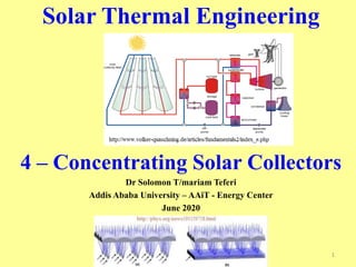
1. Solar Thermal Engineering
4 – Concentrating Solar Collectors
Dr Solomon T/mariam Teferi
Addis Ababa University – AAiT - Energy Center
June 2020
1
2. For applications such as air conditioning, central power
generation, and numerous industrial heat requirements,
flat plate collectors generally cannot provide carrier fluids
at temperatures sufficiently elevated to be effective.
In this case, alternatively, more complex and expensive
concentrating collectors can be used.
These are devices that optically focus incident solar energy
onto a small receiving area. As a result of this concentration,
the intensity of the solar energy is magnified, and the
temperatures that can be achieved at the receiver (target) can
approach several hundred or even several thousand degrees
Celsius.
The concentrators must move to track the sun if they are to
perform effectively
However, diffused sky radiation cannot be focused onto the
absorber 2
3. 4.1 TYPE OF CONCENTRATING SOLAR
COLLECTORS
1. Cylindrical trough
2. Parabolic trough system
3. Parabolic dish system
4. Power tower system
5. Fresnel lens for solar concentrator 3
4. Possible Concentrating Collector Configurations
4
(a) tubular absorbers with diffuse back reflector;
(b) tubular absorbers with specular cusp reflectors
(c) plane receiver with plane reflectors
(d) parabolic concentrator
(e) Fresnel reflector
(f) array of heliostats with central receiver.
6. Parabolic trough Solar Collectors
line focus collectors
The troughs concentrate sunlight onto a receiver tube
that is positioned along the focal line of the trough.
Temperatures at the receiver can reach 400°C and
produce steam for generating electricity
6
7. Parabolic Dish (Paraboloid ) Solar
Collectors – Point focus
A parabolic dish collector is similar in appearance
to a large satellite dish, but has mirror-like reflectors
and an absorber at the focal point.
uses a dual axis sun tracker
uses a computer to track the sun and concentrate the
sun's rays onto a receiver located at the focal point in
front of the dish.
In some systems, a heat engine, such as a Stirling
engine, is linked to the receiver to generate electricity.
Parabolic dish systems can reach 1000°C at the
receiver
7
8. Solar Power tower system
http://www.thermosolglass.com/solar/
An array of sun tracking flat mirrors called heliostats
concentrates irradiation from the sun onto a receiver, atop a
central tower.
This receiver contains a heat‐transfer fluid (water/molten salts) that upon
absorption of highly concentrated thermal energy gets converted to steam
which drives the turbine to generate electricity.
8
9. The components of power tower system
Heliostats
A Heliostat is a device that reflects its incident direct solar radiation onto
a receiver.
• Its components include a reflective surface, usually in the form of flat mirrors, a
supporting structure and a motorized system to track the movement of the sun. The
heliostat design must ensure that radiation is delivered to the receiver at the desired
flux density at minimum cost.
Receiver
The enormous amount of energy thus received, produces temperatures of
550°C to 1500°C.
• The receiver then transfers this heat to a heat-transfer fluid that may either be
water/steam, liquid sodium, or molten nitrate salt (sodium nitrate/potassium nitrate).
Tower
The tower acts as a pillar on which the receiver rests. The height of
the tower should be such that it rises above the heliostats level to
avoid, or at least reduce, shades and blockings.
9
10. Fresnel lens for solar concentrator
http://www.ntkj.co.jp/
Solar concentrator fresnel lenses have originally been
developed for concentrating photovoltaic application.
The solar concentrator fresnel lenses are designed its plano side
to face the sun (parallel light source), and the fresnel surface to
face photovoltaic cells (focus).
These lenses are also used as a solar energy concentrator for
solar furnaces.
10
11. Highlights the Key Features of the Three Solar Technologies
http://www.geocities.com/dieret/re/Solar/solar.html
11
Parabolic Trough Dish/Engine Power Tower
Size 30-320 MW 5-25 kW 10-200 MW
Operating
Temperature (ºC)
390 750 565
Annual Capacity
Factor
23-50 % 25 % 20-77 %
Peak Efficiency 20%(d) 29.4%(d) 23%(p)
Net Annual
Efficiency
11(d)-16% 12-25%(p) 7(d)-20%
Commercial Status
Commercially Scale-
up Prototype
Demonstration
Available
Demonstration
Technology
Development Risk
Low High Medium
Storage Available Limited Battery Yes
Hybrid Designs Yes Yes Yes
Cost USD/W 2.7 - 4.0 1.3 - 12.6 2.5 - 4.4
(p) = predicted; (d) = demonstrated;
12. 4.2 CONCENTRATION RATIO
The most common definition of concentration
ratio is an area concentration ratio, the ratio of
the area of aperture (Ap or Aa) to the area of the
receiver (Ar) .
The area concentration ratio is simply called
concentration ratio
This ratio has an upper limit that depends on
whether the concentration is a three dimensional
(circular or point) concentrator such as a paraboloid
or a two-dimensional (linear) concentrator such as
a cylindrical parabolic concentrator. 12
13. Schematic of sun at Ts at distance R from a
concentrator with aperture area A and receiver area
Rabl (1976a).
Consider the circular concentrator with aperture area
Aa and receiver area Ar viewing the sun of radius r at
distance R, as shown in the figure.
The half-angle subtended by the sun is θs. 13
14. If the concentrator is perfect, the radiation from the sun
on the aperture (and thus also on the receiver) is the
fraction of the radiation emitted by the sun which is
intercepted by the aperture.
Although the sun is not a blackbody, for purposes of an
approximate analysis it can be assumed to be a
blackbody at Ts.
A perfect receiver (i.e., blackbody) radiates energy
equal to ArTr
4 , and a fraction of this, Er-s, reaches the
sun.
14
15. When Tr and Ts are the same, the second law of
thermodynamics requires that Qs→r be equal to Qr→s.
So from Equations 2 and 3.
and since the maximum value of Er-s is unity, the
maximum concentration ratio for circular
concentrators is
A similar development for linear concentrators leads to
15
16. Non-imaging and Imaging Concentrators
Non-imaging concentrators as the name implies, do not
produce clearly defined images of the sun on the
absorber but rather distribute radiation from all parts of
the solar disk onto all parts of the absorber. The
concentration ratios of linear non-imaging collectors are
in the low range and are generally below 10.
Imaging concentrators, in contrast, are analogous to
camera lenses in that they form images (usually of very
low quality by ordinary optical standards) on the
absorber.
16
17. 4.3 THERMAL PERFORMANCE
OF
CONCENTRATING COLLECTORS
Calculation of the performance of concentrating collectors
follows the same general outlines as for flat-plate
collectors.
However, the methods for calculating thermal losses from
receivers are not as easily summarized as in the case of flat-
plate collectors.
The shapes and designs are widely variable, the
temperatures are higher, the edge effects are more
significant, conduction terms may be quite high, and the
problems may be compounded by non-uniformity of
radiation flux on receivers which can result in substantial
temperature gradients across the energy absorbing surfaces.
17
18. Let us consider an uncovered cylindrical absorbing tube used
as a receiver with a linear concentrator.
Assume that there are no temperature gradients around the
receiver tube.
The loss and loss coefficient considering convection and
radiation from the surface and conduction through the support
structure are
The linearized radiation coefficient can be calculated from
18
19. If a single value of UL is not acceptable due to large temperature gradients
in the flow direction, the collector can be considered as divided into
segments each with constant UL.
For estimation of convection heat transfer coefficient, hw, refer section 3.15
of the text book.
Estimation of conductive losses must be based on knowledge of the
construction details or on measurements on a particular collector.
Linear concentrators may be fitted with cylindrical absorbers surrounded by
transparent tubular covers.
For a collector of length L the heat transfer from the receiver at Tr to the
inside of the cover at Tci through the cover to Tco and then to the
surroundings at Ta and Tsky is given by
The cover thermal conductivity is kc and keff is an effective conductivity for convection between the receiver
and the cover
19
23. From equation (9)
Since 137.8 is not approximalety equal to 99.5 (the difference is +38.3), our
initial guess of the outside cover temperature was too low. A second guess of the
outside cover temperature of 295 K has an error of −27.8 W.
Linear interpolation to find the temperature where the error is near
zero yields a cover temperature of 292.9 K.
With this new cover temperature the loss calculated from Equations (9) and (11)
are virtually identical and equal to 136.7 W.
The loss coefficient (based on receiver area) is found from the definition given
by Equation (7) as
A collector that has a significant temperature change in the flow direction should
be divided into a number of small sections.
23
24. The overall heat transfer coefficient (based on the outside receiver tube
diameter) between the surroundings and the fluid is
• Where, Di and Do are the inside and outside tube diameters, hfi is the heat transfer
coefficient inside the tube, and k is the thermal conductivity of the tube.
The useful energy gain per unit of collector length qu’, expressed in
terms of local receiver temperature Tr and the absorbed solar radiation
per unit of aperture area S, is
Aa is the unshaded area of the concentrator aperture and Ar is the area of
the receiver (πDoL for the cylindrical absorber).
In terms of the energy transfer to the fluid at local fluid temperature Tf,
24
25. If Tr is eliminated from the Equations
where the collector efficiency factor F’ is given as
Hence
In a manner analogous to that for a flat-plate
collector, the collector flow factor F is given as
26. The differences between covered and uncovered
receivers are in the calculations of S and U.
If a receiver of this type serves as a boiler, F’ is
given by Equation (16), but FR is then identically
equal to F’ as there is no temperature gradient in
the flow direction.
If a part of the receiver serves as a boiler and
other parts as fluid heaters, the two or three
segments of the receiver must be treated
separately.
30. 30
Concentrating Collectors Reflectivity for Mirror Surfaces
Material r
Silver 0.93-0.95
Back silvered low iron glass 0.88
Back aluminiumised glass 0.76-0.80
Plated silver 0.96
Aluminium sheet 0.82
Aluminiumised PTFE 0.77
Silvered PTFE 0.86
31. 4.4 OPTICAL PERFORMANCE
CONCENTRATING COLLECTORS
Concentrating collectors have optical properties that vary
substantially with the geometry of the device.
The following equation for the absorbed energy (S) can be applied
to all concentrators though the ways in which they are applied vary
with configuration.
γ, τ and α are function of the angle of incidence of radiation on the
aperture.
The intercept factor γ is defined as the fraction of the reflected
radiation that is incident on the absorbing surface of the receiver.
Kγτα is an incidence angle modifier to be used to account for deviations
from the normal of the angle of incidence of the radiation on the aperture.
31
32. 4.5 PARABOLIC TROUGH SOLAR COLLECTORS
Linear Imaging Concentrators
The Parabola (http://www.powerfromthesun.net/)
A parabola is the locus of a point that
moves so that its distances from a fixed
line and a fixed point are equal.
• The fixed line is called the directrix and the
fixed point F is the focus.
• Note that the length FR equals the length RD.
• The line perpendicular to the directrix and
passing through the focus F is called the axis
of the parabola.
• The parabola intersects its axis at a
point V called the vertex, which is exactly
midway between the focus and the directrix.
Temperature in the range of 100 to 500oC
32
33. The equation of the parabola, in terms of
the coordinate system is
y2 = 4fx (14)
The aperture is a and the focal length (the
distance from the focal point to the vertex)
is f.
The radiation beam shown in the figure is
incident on the reflector at point B at the
rim where the mirror radius is a
maximum at rr. The angle φr is the rim
angle, described by AFB, and is given by
For any point of the parabolic reflector the
local mirror radius is
33
34. An incident beam of solar radiation is a cone with an angular
width of 0.53 (i.e., a half-angle θs of 0.267o or 16’).
For simplification, it is assumed that the concentrator is
symmetrical and that the beam radiation is normal to the
aperture.
The width of the solar image in the focal plane increases
with increasing rim angle. 34
35. The minimum sizes of flat, circular, and semicircular receivers
centered at the focal point to intercept all of the reflected
radiation are shown in the figure below.
It is clear from this diagram that the angle of incidence of
radiation on the surface of any of these receiver shapes is
variable.
35
36. For specular parabolic reflectors of perfect shape
and alignment, the size of the receiver to intercept
all of the solar image can be calculated.
The diameter D of a cylindrical receiver is given as
For a flat receiver in the focal plane of the parabola
(the y-z plane through F), the width W is given as
36
37. Images Formed by Perfect Linear
Concentrators
Let images formed on planes perpendicular to the
axis of the parabola be considered;
Perfectly oriented cylindrical parabolic reflectors
The radiation incident on a differential element of area
of a reflector can be thought of as a cone having an apex
angle of (0.53o) 32’, or a half-angle of 0.255o(16’).
The reflected radiation from the element will be a
similar cone and will have the same apex angle if the
reflector is perfect. The intersection of this cone with
the receiver surface determines the image size and
shape for that element, and the total image is the sum
of the images for all of the elements of the reflector. 37
38. Consider a flat receiver perpendicular to the axis of a
perfect parabola at its focal point, with beam radiation
normal to the aperture.
The intersection of the focal plane and a cone of
reflected radiation from an element is an ellipse, with
minor axis of 2r sin 16 and major
axis of y1 − y2, where y1= r sin 16’ / cos(φ − 16’ ) and
y2 = r sin 16 / cos(φ + 16’ ).
The local concentration ratio Cl = I (y)/Ib,ap is the ratio
of intensity at any position y in the image to the
intensity on the aperture of the concentrator.
38
41. Images from Imperfect Linear Concentrators
The distributions shown in Figures 7.10.1 to
7.10.3 are for perfect parabolic cylinders.
If a reflector has small, two-dimensional surface
slope errors that are normally distributed, the
images in the focal plane created by these
reflectors for perfect alignment will be as shown
in Figure 7.11.1. Distributions for reflectors with
rim angles of 30o and 75o are shown for various
values of the standard deviation of the normally
distributed slope errors.
Imperfect reflectors will, as is intuitively obvious,
produce larger images than the theoretical. 41
42. A second method of accounting for imperfections in the
shape of a parabola is to consider the reflected beam as
having an angular width of (0.53 + δ) degrees, where δ is a
dispersion angle, as shown in Figure 7.11.2.
42
45. 4.6 OPTICAL CHARACTERISTICS OF
NONIMAGING CONCENTRATORS
It is possible to construct concentrating collectors
that can function seasonally or annually with
minimum requirements for tracking.
Example of such concentration collector are
compound parabolic concentrators.
• Joint the rim point of one parabola with the focal point
of second parabola. And repeat this for by joining the
rim of the second parabola with the focal point of the
first parabola.
•The angle b/n these two lines is the acceptance angle.
Angle b/n one of these lines and the axis of the CPC is
half acceptance angle
•Remove the extra parts of the parabolas
In Such concentrators, if the reflector is perfect, any
radiation entering the aperture at angles between ± θ
will be reflected to a receiver at the base of the
concentrator by specularly reflecting parabolic reflectors. 45
46. 46
CPCs can collect diffuse radiation with a proportion of
1/C (C of 1.5 will pick up 2/3 of diffuse radiation)
48. Concentration ratio
An ideal CPC is one which has parabolas with no errors.
• Thus an ideal CPC with an acceptance half-angle of 23.5o will have Ci =
2.51, and one with an acceptance half-angle of 11.75o will have Ci = 4.91.
The figure below shows the fraction of radiation incident on the
aperture at angle θ which reaches the absorber as a function of θ.
48
49. For the ideal CPC, the fraction is unity out
to θc and zero beyond. For a real CPC with
surface errors, some radiation incident at
angles less than θc does not reach the
absorber, and some at angles greater than
θc does reach it.
At the upper end points of the parabolas in
a CPC, the surfaces are parallel to the
central plane of symmetry of the
concentrator.
The upper ends of the reflectors thus
contribute little to the radiation reaching the
absorber, and the CPC can be truncated to
reduce its height from h to h’ with a resulting
saving in reflector area but little sacrifice in
performance.
A truncated CPC is shown in the figure. The
dashed plot in Figure 7.6.2 shows the spread
49
50. Limited truncation
affects the acceptance angle very little
but it does change the height-to-aperture ratio, the
concentration ratio, and the average number of reflections
undergone by radiation before it reaches the absorber surface.
The effects of truncation are shown for otherwise ideal
CPCs in the following figures of the values can be
calculated using equation 16 to equation 23.
50
55. Where ART is the reflector area per unit depth of a truncated
CPC (if φT = 2θc, then ART = AR), ni is the average number of
reflections, and the other variables are shown in the figure
below
55
59. 4.7 PARABOLOIDAL CONCENTRATORS
In the previous sections methods were outlined
for calculation of absorbed radiation for
collectors with linear parabolic concentrators.
A similar analysis can be done for collectors with
three-dimensional parabolic reflectors, that is,
concentrators that are surfaces of revolution.
Rabl (1976a, 1985) summarizes important optical
aspects of these collectors.
the rim angle φr and mirror radius r are analogous
to those for the linear concentrator. 59
60. 4.7 CENTRAL RECEIVER COLLECTOR
a large number of heliostats are reflecting beam
radiation onto a central receiver.
The result is a Fresnel-type concentrator, a parabolic
reflector broken up into small segments
Several additional optical phenomena must be
taken into account.
Shading and blocking can occur (shading of incident
beam radiation from a heliostat by another heliostat
and blocking of reflected radiation from a heliostat
by another which prevents that radiation from
reaching the receiver). 60
61. As a result of these considerations, the heliostats are spaced
apart, and only a fraction of the ground area ψ is covered by
mirrors. A ψ of about 0.3 to 0.5 has been suggested as a
practical value.
The maximum concentration ratio for a three-dimensional
concentrator system with radiation incident at an angle θi on
the plane of the heliostat array (θi = θz for a horizontal array),
a rim angle of φr , and a dispersion angle of δ, if all reflected
beam radiation is to be intercepted by a spherical receiver, is
61