Recommended
PPTX
Chapter 11 1-3-Intermolecular Forces.pptx
PPT
PPT
PPT
PPTX
PPT
intermolecular_forces.ppt
PPT
intermolecular_forces.ppt
PPT
PPTX
2.-LESSON-2-INTERMOLECULAR-FORCE-OF-ATTRACTION.pptx
PPTX
Intermolecular and Intramolecular...pptx
PPTX
Intermolecular and Intramolecular...pptx
PPTX
Intermolecular Forces and Liquids and Solids.pptx
PPT
ap ch 11 intermolecular forces.ppt
PPT
intermolecular forces.ppt
PPT
ap ch 11 intermolecular forces.ppt
PPT
ap ch 11 intermolecular forces.ppt
PPT
PDF
Intermolecular forces module
PDF
Lecture 2-3. intermolecular forzes.pptx.pdf
PPT
Chapter 11 liquids and intermolecular forces Powerpoint
PDF
PHYSICAL-SCIENCE-Q3-Week-3_v2.pdf moreno
PPTX
Tang 09 intermolecular forces and solubility
PPT
Intermolecular_Forces_Liquids_and_Solids-Autosaved.ppt
PPTX
PPTX
PHYSICALSCIENCE Intermolecular-Forces.ppt.pptx
PPTX
Chapter 11 PowerPoint Lecture on Intermolecular Forces of Attraction.pptx
PDF
Interaction of Molecules in 3D Space: Determining Binding and Dissociation Co...
PPTX
Powerpoint for chapter 11.pptx
PPTX
Chapter3-power-points-Kotz1.pptx.........
PPT
CHEM12_C11_L3_LO (1).ppt.....................
More Related Content
PPTX
Chapter 11 1-3-Intermolecular Forces.pptx
PPT
PPT
PPT
PPTX
PPT
intermolecular_forces.ppt
PPT
intermolecular_forces.ppt
PPT
Similar to Zumdahl10e_PPT_Ch10.pptx.........................
PPTX
2.-LESSON-2-INTERMOLECULAR-FORCE-OF-ATTRACTION.pptx
PPTX
Intermolecular and Intramolecular...pptx
PPTX
Intermolecular and Intramolecular...pptx
PPTX
Intermolecular Forces and Liquids and Solids.pptx
PPT
ap ch 11 intermolecular forces.ppt
PPT
intermolecular forces.ppt
PPT
ap ch 11 intermolecular forces.ppt
PPT
ap ch 11 intermolecular forces.ppt
PPT
PDF
Intermolecular forces module
PDF
Lecture 2-3. intermolecular forzes.pptx.pdf
PPT
Chapter 11 liquids and intermolecular forces Powerpoint
PDF
PHYSICAL-SCIENCE-Q3-Week-3_v2.pdf moreno
PPTX
Tang 09 intermolecular forces and solubility
PPT
Intermolecular_Forces_Liquids_and_Solids-Autosaved.ppt
PPTX
PPTX
PHYSICALSCIENCE Intermolecular-Forces.ppt.pptx
PPTX
Chapter 11 PowerPoint Lecture on Intermolecular Forces of Attraction.pptx
PDF
Interaction of Molecules in 3D Space: Determining Binding and Dissociation Co...
PPTX
Powerpoint for chapter 11.pptx
More from KevWatts
PPTX
Chapter3-power-points-Kotz1.pptx.........
PPT
CHEM12_C11_L3_LO (1).ppt.....................
PPT
chapter_12_stoichiometry_-_powerpoint.ppt
PPTX
Atomic Structure Lesson Part 3.pptx.....
PPT
beerlambert-140929110335-phpapp02.ppt....
PPTX
Copy of Periodic Trends PowerPoint.pptx.
PPTX
Unit 3 lecture notes.pptx......................
PPTX
U6L6.pptx...............................
PPTX
U6L5.pptx.................................
PPT
gas_laws_part_1.ppt........................
PPTX
solutions.pptx............................
PPT
9221397.ppt..............................
PPT
Honors Chemistry ch 5.ppt/////////////////////
PPT
Honors Chemistry ch 5.ppt............................
PPTX
Section A3 - Bonding.pptx...................
PPT
iGCSE Chemistry Section 1 Lesson 1.ppt..
PPTX
U5L1P2.pptx......................................
PPTX
U5L1P1.pptx........................................
PPTX
Zumdahl10e_PPT_Ch11.pptx................
PPT
C8_U4_L4_TransitionMetalNomenclature.ppt
Recently uploaded
PPTX
Chapter 1: Introduction to Strategic Management.pptx
PDF
PPT Daftar Bahan Kelas Bedah Kitab Matius Khotbah di Bukit
PDF
Pratishta Educational Society., Courses & Opportunities
PPTX
GRADE 8 - QUARTER 4 TYPES AND PARTS OF LETTER.pptx
PPTX
A brief introduction to Minor vegetable crops.pptx
PPTX
Guidelines for reporting social networks and personal networks data
PDF
Types of Foot & Foot Modifications in Birds
PDF
How "Raiders of the Lost Ark" and "Ordinary People" Employ Non-Verbal Acting
PDF
PHARMACOLOGY 1 ( BP 404 T) Unit 1 (Cology 1)
PDF
Chapter 05 Drugs Acting on the Central Nervous System: Anti-Depressant Drugs
PDF
Tetracycline Class of Antibiotics: SAR, MOA and Uses
PDF
AI Is a Tool, Not a Voice: Radio, Trust, and the Human Factor
PDF
Orlando by Virginia Woolf: The Granite and The Rainbow
PPTX
Lesson_1 Acceleration.pptx_Science 8-4th quarter
PPTX
How to Track & Manage My Time Section in Odoo 18 Time Off
PDF
Judgement Regarding Land Acquisition Act not Applicable to Encroachers.pdf
PPTX
ENGLISH-7-Quarter-4-Week-3 Matatag .pptx
PDF
Chapter 05 Drugs Acting on the Central Nervous System: Anticonvulsant (Antiep...
PPTX
How to Track Employee Skill Growth with Skills Evolution Report in Odoo 18
PPTX
Math 8 Quarter 4 Week 4-SECONDARY DATA.pptx
Zumdahl10e_PPT_Ch10.pptx......................... 1. 2. Chapter 10
Table of Contents
Copyright ©2017 Cengage Learning. All Rights Reserved.
Table of Contents
(10.1) Intermolecular forces
(10.2) The liquid state
(10.3) An introduction to structures and types
of solids
(10.4) Structure and bonding in metals
(10.5) Carbon and silicon: Network atomic
solids
3. Chapter 10
Table of Contents
Copyright ©2017 Cengage Learning. All Rights Reserved.
Table of Contents Continued
(10.6) Molecular solids
(10.7) Ionic solids
(10.8) Vapor pressure and changes of state
(10.9) Phase diagrams
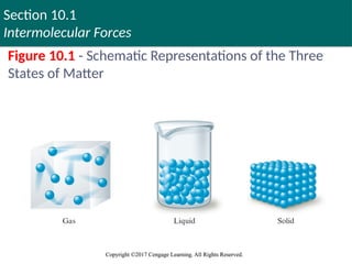
4. 5. Section 10.1
Intermolecular Forces
Copyright ©2017 Cengage Learning. All Rights Reserved.
Copyright ©2017 Cengage Learning. All Rights Reserved.
Intramolecular and Intermolecular Bonding
Intramolecular bonding - Occurs within molecules
Condensed states of matter - Liquids and solids
Forces involved
Covalent bonding
Ionic bonding
Intermolecular bonding: Occurs between molecules
Copyright © Cengage Learning. All rights reserved 5
6. Section 10.1
Intermolecular Forces
Copyright ©2017 Cengage Learning. All Rights Reserved.
Copyright ©2017 Cengage Learning. All Rights Reserved.
Changes in States
When a substance changes from solid to liquid to
gas, the molecules remain intact
Caused by the changes in the forces among the
molecules and not within the molecules
When energy is added to ice, the motion of the
molecules increases
Results in greater movement and disorder characteristic of
liquid water
7. Section 10.1
Intermolecular Forces
Copyright ©2017 Cengage Learning. All Rights Reserved.
Copyright ©2017 Cengage Learning. All Rights Reserved.
Changes in States (Continued)
When more energy is added to water, gaseous state is
eventually reached
Intermolecular distance increases, and intermolecular
interaction decreases
More energy is required to overcome the covalent
bonds and decompose the water molecules into their
component atoms
8. Section 10.1
Intermolecular Forces
Copyright ©2017 Cengage Learning. All Rights Reserved.
Copyright ©2017 Cengage Learning. All Rights Reserved.
Dipole–Dipole Forces
Forces that act between polar molecules
Dipole–dipole attraction: Electrostatic attraction
between molecules with dipole moments
Molecules orient themselves in a way that the positive
and negative ends are close to each other
In a condensed state, dipoles find the best
compromise between attraction and repulsion
9. Section 10.1
Intermolecular Forces
Copyright ©2017 Cengage Learning. All Rights Reserved.
Copyright ©2017 Cengage Learning. All Rights Reserved.
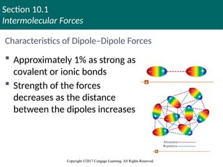
Characteristics of Dipole–Dipole Forces
Approximately 1% as strong as
covalent or ionic bonds
Strength of the forces
decreases as the distance
between the dipoles increases
10. Section 10.1
Intermolecular Forces
Copyright ©2017 Cengage Learning. All Rights Reserved.
Copyright ©2017 Cengage Learning. All Rights Reserved.
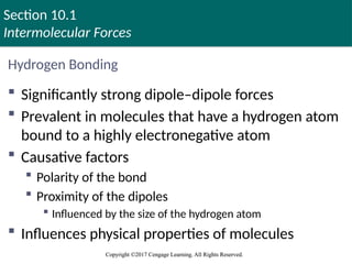
Hydrogen Bonding
Significantly strong dipole–dipole forces
Prevalent in molecules that have a hydrogen atom
bound to a highly electronegative atom
Causative factors
Polarity of the bond
Proximity of the dipoles
Influenced by the size of the hydrogen atom
Influences physical properties of molecules
11. Section 10.1
Intermolecular Forces
Copyright ©2017 Cengage Learning. All Rights Reserved.
Copyright ©2017 Cengage Learning. All Rights Reserved.
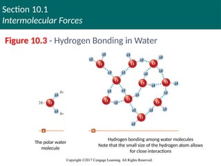
Figure 10.3 - Hydrogen Bonding in Water
The polar water
molecule
Hydrogen bonding among water molecules
Note that the small size of the hydrogen atom allows
for close interactions
12. Section 10.1
Intermolecular Forces
Copyright ©2017 Cengage Learning. All Rights Reserved.
Copyright ©2017 Cengage Learning. All Rights Reserved.
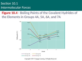
Figure 10.4 - Boiling Points of the Covalent Hydrides of
the Elements in Groups 4A, 5A, 6A, and 7A
13. Section 10.1
Intermolecular Forces
Copyright ©2017 Cengage Learning. All Rights Reserved.
Copyright ©2017 Cengage Learning. All Rights Reserved.
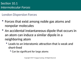
London Dispersion Forces
Forces that exist among noble gas atoms and
nonpolar molecules
An accidental instantaneous dipole that occurs in
an atom can induce a similar dipole in a
neighboring atom
Leads to an interatomic attraction that is weak and
short-lived
Can be significant for large atoms
14. Section 10.1
Intermolecular Forces
Copyright ©2017 Cengage Learning. All Rights Reserved.
Copyright ©2017 Cengage Learning. All Rights Reserved.
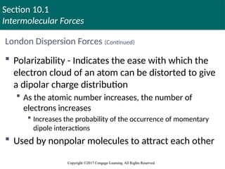
London Dispersion Forces (Continued)
Polarizability - Indicates the ease with which the
electron cloud of an atom can be distorted to give
a dipolar charge distribution
As the atomic number increases, the number of
electrons increases
Increases the probability of the occurrence of momentary
dipole interactions
Used by nonpolar molecules to attract each other
15. Section 10.1
Intermolecular Forces
Copyright ©2017 Cengage Learning. All Rights Reserved.
Copyright ©2017 Cengage Learning. All Rights Reserved.
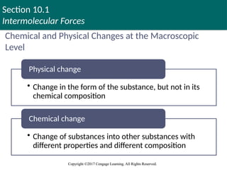
Chemical and Physical Changes at the Macroscopic
Level
• Change in the form of the substance, but not in its
chemical composition
Physical change
• Change of substances into other substances with
different properties and different composition
Chemical change
16. Section 10.1
Intermolecular Forces
Copyright ©2017 Cengage Learning. All Rights Reserved.
Copyright ©2017 Cengage Learning. All Rights Reserved.
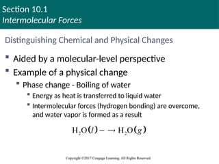
Distinguishing Chemical and Physical Changes
Aided by a molecular-level perspective
Example of a physical change
Phase change - Boiling of water
Energy as heat is transferred to liquid water
Intermolecular forces (hydrogen bonding) are overcome,
and water vapor is formed as a result
2 2
H O H O
l g
17. Section 10.1
Intermolecular Forces
Copyright ©2017 Cengage Learning. All Rights Reserved.
Copyright ©2017 Cengage Learning. All Rights Reserved.
Distinguishing Chemical and Physical Changes (continued)
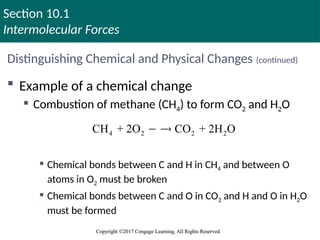
Example of a chemical change
Combustion of methane (CH4) to form CO2 and H2O
Chemical bonds between C and H in CH4 and between O
atoms in O2 must be broken
Chemical bonds between C and O in CO2 and H and O in H2O
must be formed
4 2 2 2
CH + 2O CO + 2H O
18. Section 10.1
Intermolecular Forces
Copyright ©2017 Cengage Learning. All Rights Reserved.
Copyright ©2017 Cengage Learning. All Rights Reserved.
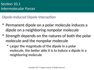
Dipole-Induced Dipole Interaction
Permanent dipole on a polar molecule induces a
dipole on a neighboring nonpolar molecule
Strength depends on the natures of both the polar
molecule and the nonpolar molecule
Larger the magnitude of the dipole in a polar
molecule, the better able it is to induce a dipole in a
neighboring molecule
19. Section 10.1
Intermolecular Forces
Copyright ©2017 Cengage Learning. All Rights Reserved.
Copyright ©2017 Cengage Learning. All Rights Reserved.
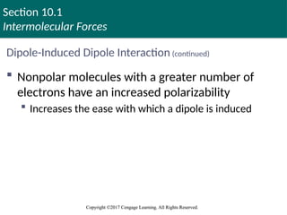
Dipole-Induced Dipole Interaction (continued)
Nonpolar molecules with a greater number of
electrons have an increased polarizability
Increases the ease with which a dipole is induced
20. Section 10.1
Intermolecular Forces
Copyright ©2017 Cengage Learning. All Rights Reserved.
Copyright ©2017 Cengage Learning. All Rights Reserved.
Critical Thinking
You have learned the difference between
intermolecular forces and intramolecular bonds
What if intermolecular forces were stronger than
intramolecular bonds?
What differences could you observe in the world?
21. Section 10.1
Intermolecular Forces
Copyright ©2017 Cengage Learning. All Rights Reserved.
Copyright ©2017 Cengage Learning. All Rights Reserved.
Join In (1)
Which one of the following is the strongest
intermolecular force experienced by noble gases?
a. London dispersion forces
b. Dipole–dipole attraction
c. Hydrogen bonding
d. Ion–ion interactions
22. Section 10.1
Intermolecular Forces
Copyright ©2017 Cengage Learning. All Rights Reserved.
Copyright ©2017 Cengage Learning. All Rights Reserved.
Join In (2)
Methane (CH4) is a gas, but carbon tetrachloride
(CCl4) is a liquid at room conditions
Which of the following statements explains this
phenomenon?
a. CCl4 is a polar molecule and CH4 is not
b. CCl4 and CH4 have different geometries and shapes
c. CH4 exhibits hydrogen bonding and CCl4 does not
d. Cl is more electronegative than H
e. None of these statements is correct
23. Section 10.1
Intermolecular Forces
Copyright ©2017 Cengage Learning. All Rights Reserved.
Copyright ©2017 Cengage Learning. All Rights Reserved.
Join In (3)
Which of the following species exhibits the
strongest intermolecular forces?
a. CH4
b. H2O
c. N2
d. CO
e. He
24. Section 10.1
Intermolecular Forces
Copyright ©2017 Cengage Learning. All Rights Reserved.
Copyright ©2017 Cengage Learning. All Rights Reserved.
Join In (4)
What type(s) of intermolecular forces is (are)
exhibited by methane (CH4)?
a. Hydrogen bonding and London dispersion forces
b. Hydrogen bonding
c. Dipole–dipole and London dispersion forces
d. London dispersion forces
25. Section 10.1
Intermolecular Forces
Copyright ©2017 Cengage Learning. All Rights Reserved.
Copyright ©2017 Cengage Learning. All Rights Reserved.
Join In (5)
When a water molecule forms a hydrogen bond
with another water molecule, which atoms are
involved in the interaction?
a. A hydrogen atom from one water molecule and a
hydrogen atom from the other water molecule
b. An oxygen atom from one water molecule and an
oxygen atom from the other water molecule
26. Section 10.1
Intermolecular Forces
Copyright ©2017 Cengage Learning. All Rights Reserved.
Copyright ©2017 Cengage Learning. All Rights Reserved.
Join In (5) (continued)
c. A hydrogen atom from one water molecule and an
oxygen atom from the other water molecule
d. Two hydrogen atoms from one water molecule and
one hydrogen atom from the other water molecule
e. A hydrogen atom and an oxygen atom from the same
water molecule
27. Section 10.1
Intermolecular Forces
Copyright ©2017 Cengage Learning. All Rights Reserved.
Copyright ©2017 Cengage Learning. All Rights Reserved.
Join In (6)
Which of the following has the highest boiling
point?
a. H2O
b. HF
c. NH3
d. N2
e. Na2S
28. Section 10.1
Intermolecular Forces
Copyright ©2017 Cengage Learning. All Rights Reserved.
Copyright ©2017 Cengage Learning. All Rights Reserved.
Join In (7)
Which intermolecular force below is the
strongest?
a. Dipole–dipole forces
b. London dispersion forces
c. Hydrogen bonding
29. Section 10.1
Intermolecular Forces
Copyright ©2017 Cengage Learning. All Rights Reserved.
Copyright ©2017 Cengage Learning. All Rights Reserved.
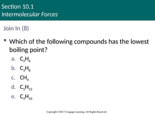
Join In (8)
Which of the following compounds has the lowest
boiling point?
a. C2H6
b. C3H8
c. CH4
d. C5H12
e. C4H10
30. Section 10.1
Intermolecular Forces
Copyright ©2017 Cengage Learning. All Rights Reserved.
Copyright ©2017 Cengage Learning. All Rights Reserved.
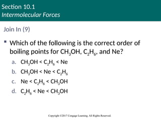
Join In (9)
Which of the following is the correct order of
boiling points for CH3OH, C2H6, and Ne?
a. CH3OH < C2H6 < Ne
b. CH3OH < Ne < C2H6
c. Ne < C2H6 < CH3OH
d. C2H6 < Ne < CH3OH
31. Section 10.2
The Liquid State
Copyright ©2017 Cengage Learning. All Rights Reserved.
Liquids
Possess low compressibility, lack rigidity, and have
high density compared with gases
Surface tension: Resistance of a liquid to an
increase in its surface area
Liquids with large intermolecular forces tend to have
high surface tensions
Copyright © Cengage Learning. All rights reserved 31
32. Section 10.2
The Liquid State
Copyright ©2017 Cengage Learning. All Rights Reserved.
Liquids (Continued)
Polar liquids exhibit capillary action
Capillary action: Spontaneous rising of a liquid in a
narrow tube
Cohesive forces - Intermolecular forces among the
molecules of the liquid
Adhesive forces - Forces between the liquid molecules and
the walls of the container
Copyright © Cengage Learning. All rights reserved 32
33. Section 10.2
The Liquid State
Copyright ©2017 Cengage Learning. All Rights Reserved.
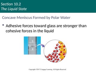
Concave Meniscus Formed by Polar Water
Adhesive forces toward glass are stronger than
cohesive forces in the liquid
Copyright © Cengage Learning. All rights reserved 33
34. Section 10.2
The Liquid State
Copyright ©2017 Cengage Learning. All Rights Reserved.
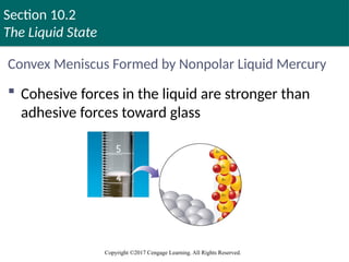
Convex Meniscus Formed by Nonpolar Liquid Mercury
Cohesive forces in the liquid are stronger than
adhesive forces toward glass
Copyright © Cengage Learning. All rights reserved 34
35. Section 10.2
The Liquid State
Copyright ©2017 Cengage Learning. All Rights Reserved.
Viscosity
Measure of a liquid’s resistance to flow
Liquids with large intermolecular forces and
complex molecules tend to be highly viscous
Example - Glycerol and grease
Copyright © Cengage Learning. All rights reserved 35
36. Section 10.2
The Liquid State
Copyright ©2017 Cengage Learning. All Rights Reserved.
Structural Model for Liquids
Have strong intermolecular forces and significant
molecular motions
Contain a large number of regions
Arrangement of the components are similar to those
that are present in solids, but with more disorder
Holes are present in a few regions
Regions are subject to rapid fluctuations
37. Section 10.2
The Liquid State
Copyright ©2017 Cengage Learning. All Rights Reserved.
Join In (10)
Consider two liquids, A and B
Liquid A exhibits stronger intermolecular forces than
liquid B
Which of the following statements is true?
a. The surface tension and viscosity of liquid A are greater
than those of liquid B
b. The surface tension of liquid A is greater than that of liquid
B; the viscosity of liquid B is greater than that of liquid A
38. Section 10.2
The Liquid State
Copyright ©2017 Cengage Learning. All Rights Reserved.
Join In (10) (continued)
c. The surface tension of liquid B is greater than that of liquid
A; the viscosity of liquid A is greater than that of liquid B
d. The surface tension and viscosity of liquid B are greater
than those of liquid A
39. Section 10.3
An Introduction to Structures and Types of Solids
Copyright ©2017 Cengage Learning. All Rights Reserved.
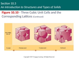
Classification of Solids
Amorphous solids: Have considerable disorder in
their structures
Crystalline solids: Characterized by highly regular
arrangement of components
Positions of components are represented by lattices
Lattice: Three-dimensional system of points designating
positions of components that make up the substance
Unit cell: Smallest repeating unit of a lattice
Copyright © Cengage Learning. All rights reserved 39
40. Section 10.3
An Introduction to Structures and Types of Solids
Copyright ©2017 Cengage Learning. All Rights Reserved.
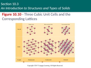
Figure 10.10 - Three Cubic Unit Cells and the
Corresponding Lattices
Copyright © Cengage Learning. All rights reserved 40
41. Section 10.3
An Introduction to Structures and Types of Solids
Copyright ©2017 Cengage Learning. All Rights Reserved.
Figure 10.10 - Three Cubic Unit Cells and the
Corresponding Lattices (Continued)
Copyright © Cengage Learning. All rights reserved 41
42. Section 10.3
An Introduction to Structures and Types of Solids
Copyright ©2017 Cengage Learning. All Rights Reserved.
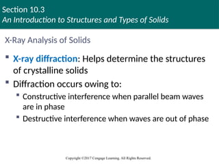
X-Ray Analysis of Solids
X-ray diffraction: Helps determine the structures
of crystalline solids
Diffraction occurs owing to:
Constructive interference when parallel beam waves
are in phase
Destructive interference when waves are out of phase
43. Section 10.3
An Introduction to Structures and Types of Solids
Copyright ©2017 Cengage Learning. All Rights Reserved.
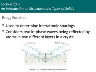
Bragg Equation
Used to determine interatomic spacings
Considers two in-phase waves being reflected by
atoms in two different layers in a crystal
44. Section 10.3
An Introduction to Structures and Types of Solids
Copyright ©2017 Cengage Learning. All Rights Reserved.
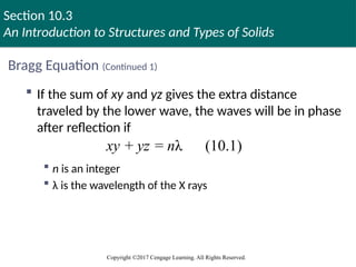
Bragg Equation (Continued 1)
If the sum of xy and yz gives the extra distance
traveled by the lower wave, the waves will be in phase
after reflection if
n is an integer
λ is the wavelength of the X rays
+ = λ (10.1)
xy yz n
45. Section 10.3
An Introduction to Structures and Types of Solids
Copyright ©2017 Cengage Learning. All Rights Reserved.
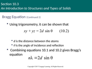
Bragg Equation (Continued 2)
Using trigonometry, it can be shown that
d is the distance between the atoms
θ is the angle of incidence and reflection
Combining equations 10.1 and 10.2 gives Bragg’s
equation
+ = 2 sin θ (10.2)
xy yz d
λ 2 sin θ
n d
46. Section 10.3
An Introduction to Structures and Types of Solids
Copyright ©2017 Cengage Learning. All Rights Reserved.
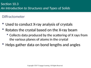
Diffractometer
Used to conduct X-ray analysis of crystals
Rotates the crystal based on the X-ray beam
Collects data produced by the scattering of X rays from
the various planes of atoms in the crystal
Helps gather data on bond lengths and angles
47. Section 10.3
An Introduction to Structures and Types of Solids
Copyright ©2017 Cengage Learning. All Rights Reserved.
Interactive Example 10.1 - Using the Bragg Equation
X rays of wavelength 1.54 Å were used to analyze
an aluminum crystal
A reflection was produced at θ = 19.3 degrees
Assuming n = 1, calculate the distance d between the
planes of atoms producing this reflection
48. Section 10.3
An Introduction to Structures and Types of Solids
Copyright ©2017 Cengage Learning. All Rights Reserved.
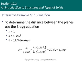
Interactive Example 10.1 - Solution
To determine the distance between the planes,
use the Bragg equation
n = 1
λ = 1.54 Å
θ = 19.3 degrees
1 1.54 Å
λ
= = = 2.33Å = 233pm
2 sin 2 0.3305
n
d
θ
49. Section 10.3
An Introduction to Structures and Types of Solids
Copyright ©2017 Cengage Learning. All Rights Reserved.
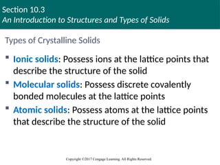
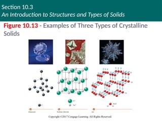
Types of Crystalline Solids
Ionic solids: Possess ions at the lattice points that
describe the structure of the solid
Molecular solids: Possess discrete covalently
bonded molecules at the lattice points
Atomic solids: Possess atoms at the lattice points
that describe the structure of the solid
Copyright © Cengage Learning. All rights reserved 49
50. Section 10.3
An Introduction to Structures and Types of Solids
Copyright ©2017 Cengage Learning. All Rights Reserved.
Figure 10.13 - Examples of Three Types of Crystalline
Solids
Copyright © Cengage Learning. All rights reserved 50
51. Section 10.3
An Introduction to Structures and Types of Solids
Copyright ©2017 Cengage Learning. All Rights Reserved.
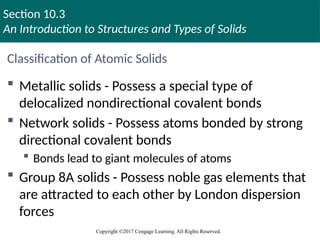
Classification of Atomic Solids
Metallic solids - Possess a special type of
delocalized nondirectional covalent bonds
Network solids - Possess atoms bonded by strong
directional covalent bonds
Bonds lead to giant molecules of atoms
Group 8A solids - Possess noble gas elements that
are attracted to each other by London dispersion
forces
52. Section 10.4
Structure and Bonding in Metals
Copyright ©2017 Cengage Learning. All Rights Reserved.
Closest Packing Model
Closest packing arrangement
Characterized by layers of uniform hard spheres that
efficiently use available space
Each sphere is surrounded by six others
Types of arrangement
The aba arrangement
The abc arrangement
Copyright © Cengage Learning. All rights reserved 52
53. Section 10.4
Structure and Bonding in Metals
Copyright ©2017 Cengage Learning. All Rights Reserved.
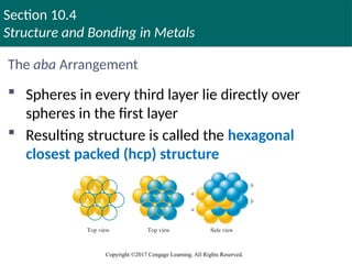
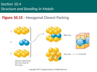
The aba Arrangement
Spheres in every third layer lie directly over
spheres in the first layer
Resulting structure is called the hexagonal
closest packed (hcp) structure
54. Section 10.4
Structure and Bonding in Metals
Copyright ©2017 Cengage Learning. All Rights Reserved.
Figure 10.15 - Hexagonal Closest Packing
55. Section 10.4
Structure and Bonding in Metals
Copyright ©2017 Cengage Learning. All Rights Reserved.
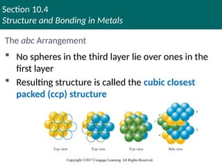
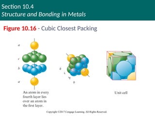
The abc Arrangement
No spheres in the third layer lie over ones in the
first layer
Resulting structure is called the cubic closest
packed (ccp) structure
56. Section 10.4
Structure and Bonding in Metals
Copyright ©2017 Cengage Learning. All Rights Reserved.
Figure 10.16 - Cubic Closest Packing
57. Section 10.4
Structure and Bonding in Metals
Copyright ©2017 Cengage Learning. All Rights Reserved.
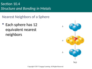
Nearest Neighbors of a Sphere
Each sphere has 12
equivalent nearest
neighbors
Copyright © Cengage Learning. All rights reserved 57
58. Section 10.4
Structure and Bonding in Metals
Copyright ©2017 Cengage Learning. All Rights Reserved.
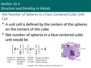
Net Number of Spheres in a Face-Centered Cubic Unit
Cell
A unit cell is defined by the centers of the spheres
on the corners of the cube
Net number of spheres in a face-centered cubic
unit would be
1 1
8× + 6× = 4
8 2
Number of
corners in a
cube
Number of
spheres that
lie inside a
unit cell
Number
of faces
in a cube
Number of central
spheres that lie
inside a unit cell
59. Section 10.4
Structure and Bonding in Metals
Copyright ©2017 Cengage Learning. All Rights Reserved.
Interactive Example 10.2 - Calculating the Density of a
Closest Packed Solid
Silver crystallizes in a cubic closest packed
structure
The radius of a silver atom is 144 pm
Calculate the density of solid silver
60. Section 10.4
Structure and Bonding in Metals
Copyright ©2017 Cengage Learning. All Rights Reserved.
Interactive Example 10.2 - Solution
Density is mass per unit volume
We need to know how many silver atoms occupy a
given volume in the crystal
The structure is cubic closest packed, which means the
unit cell is face-centered cubic
We must find the volume of this unit cell for silver and
the net number of atoms it contains
61. Section 10.4
Structure and Bonding in Metals
Copyright ©2017 Cengage Learning. All Rights Reserved.
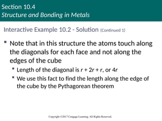
Interactive Example 10.2 - Solution (Continued 1)
Note that in this structure the atoms touch along
the diagonals for each face and not along the
edges of the cube
Length of the diagonal is r + 2r + r, or 4r
We use this fact to find the length along the edge of
the cube by the Pythagorean theorem
62. Section 10.4
Structure and Bonding in Metals
Copyright ©2017 Cengage Learning. All Rights Reserved.
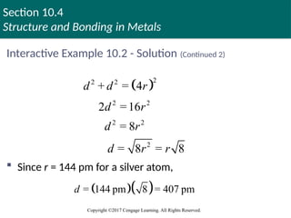
Interactive Example 10.2 - Solution (Continued 2)
2
2 2
2 2
2 2
2
+ = 4
2 =16
= 8
= 8 = 8
d d r
d r
d r
d r r
Since r = 144 pm for a silver atom,
= 144 pm 8 = 407 pm
d
63. Section 10.4
Structure and Bonding in Metals
Copyright ©2017 Cengage Learning. All Rights Reserved.
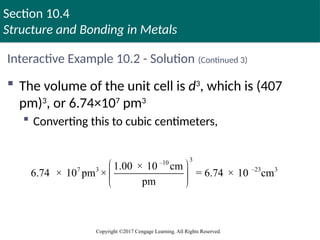
Interactive Example 10.2 - Solution (Continued 3)
The volume of the unit cell is d3
, which is (407
pm)3
, or 6.74×10⁷
pm3
Converting this to cubic centimeters,
3
–10
7 3 –23 3
1.00 × 10 cm
6.74 × 10 pm × = 6.74 × 10 cm
pm
64. Section 10.4
Structure and Bonding in Metals
Copyright ©2017 Cengage Learning. All Rights Reserved.
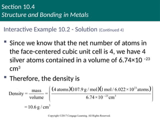
Interactive Example 10.2 - Solution (Continued 4)
Since we know that the net number of atoms in
the face-centered cubic unit cell is 4, we have 4
silver atoms contained in a volume of 6.74×10 –23
cm3
Therefore, the density is
23
–23 3
3
4 atoms 107.9 g / mol 1mol / 6.022×10 atoms
mass
Density = =
volume 6.74×10 cm
=10.6 g / cm
65. Section 10.4
Structure and Bonding in Metals
Copyright ©2017 Cengage Learning. All Rights Reserved.
Bonding Models for Metals
A successful bonding model for metals must
consider:
Malleability
Ductility
Efficient and uniform conduction of heat and
electricity
66. Section 10.4
Structure and Bonding in Metals
Copyright ©2017 Cengage Learning. All Rights Reserved.
Electron Sea Model
Envisions a regular array of metal cations in a sea
of valence electrons
Mobile electrons conduct heat and electricity
Metal ions freely move around as the metal is
hammered into a sheet or drawn into a wire
67. Section 10.4
Structure and Bonding in Metals
Copyright ©2017 Cengage Learning. All Rights Reserved.
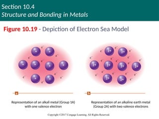
Figure 10.19 - Depiction of Electron Sea Model
Representation of an alkali metal (Group 1A)
with one valence electron
Representation of an alkaline earth metal
(Group 2A) with two valence electrons
68. Section 10.4
Structure and Bonding in Metals
Copyright ©2017 Cengage Learning. All Rights Reserved.
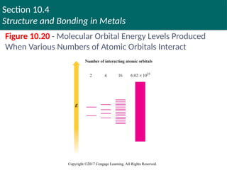
Band Model or Molecular Orbital (MO) Model
Electrons are assumed to travel around the metal
crystal in molecular orbitals formed from the
valence atomic orbitals of the metal atoms
Copyright © Cengage Learning. All rights reserved 68
69. Section 10.4
Structure and Bonding in Metals
Copyright ©2017 Cengage Learning. All Rights Reserved.
Figure 10.20 - Molecular Orbital Energy Levels Produced
When Various Numbers of Atomic Orbitals Interact
70. Section 10.4
Structure and Bonding in Metals
Copyright ©2017 Cengage Learning. All Rights Reserved.
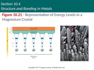
Figure 10.21 - Representation of Energy Levels in a
Magnesium Crystal
71. Section 10.4
Structure and Bonding in Metals
Copyright ©2017 Cengage Learning. All Rights Reserved.
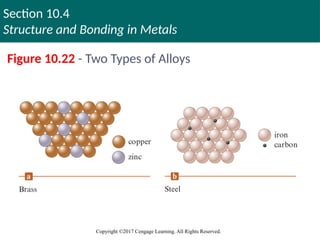
Metal Alloys
Alloy: Substance that contains a mixture of
elements and possesses metallic properties
Substitutional alloy: Some host metal atoms are
replaced by other metal atoms of similar size
Interstitial alloy: Some of the interstices in the closest
packed metal structure are occupied by small atoms
Copyright © Cengage Learning. All rights reserved 71
72. Section 10.4
Structure and Bonding in Metals
Copyright ©2017 Cengage Learning. All Rights Reserved.
Figure 10.22 - Two Types of Alloys
Copyright © Cengage Learning. All rights reserved 72
73. Section 10.4
Structure and Bonding in Metals
Copyright ©2017 Cengage Learning. All Rights Reserved.
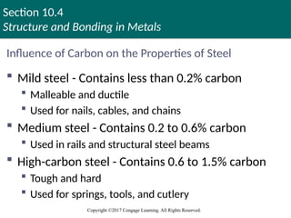
Influence of Carbon on the Properties of Steel
Mild steel - Contains less than 0.2% carbon
Malleable and ductile
Used for nails, cables, and chains
Medium steel - Contains 0.2 to 0.6% carbon
Used in rails and structural steel beams
High-carbon steel - Contains 0.6 to 1.5% carbon
Tough and hard
Used for springs, tools, and cutlery
74. Section 10.5
Carbon and Silicon: Network Atomic Solids
Copyright ©2017 Cengage Learning. All Rights Reserved.
Network Solids
Atomic solids that contain directional covalent
bonds
Form solids that are viewed as giant molecules
Properties
Brittle in nature
Ineffective conductors of heat and electricity
75. Section 10.5
Carbon and Silicon: Network Atomic Solids
Copyright ©2017 Cengage Learning. All Rights Reserved.
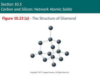
Diamond
Each carbon atom is surrounded by a tetrahedral
arrangement of other carbon atoms to form a
huge molecule
Structure fits the characteristics of the localized
electron model
Covalent bonds result in a stable structure
Formed by the overlap of sp3
hybridized carbon atomic
orbitals
76. Section 10.5
Carbon and Silicon: Network Atomic Solids
Copyright ©2017 Cengage Learning. All Rights Reserved.
Figure 10.23 (a) - The Structure of Diamond
Copyright © Cengage Learning. All rights reserved 76
77. Section 10.5
Carbon and Silicon: Network Atomic Solids
Copyright ©2017 Cengage Learning. All Rights Reserved.
Diamond (Continued)
Structure according to the MO model
A large gap between the filled and empty levels exists
Electron transfer is difficult
Diamond is not expected to be a good electrical conductor
Used in industrial cutting implements
Graphite can be converted to diamond by applying
150,000 atm of pressure at 2800°C
78. Section 10.5
Carbon and Silicon: Network Atomic Solids
Copyright ©2017 Cengage Learning. All Rights Reserved.
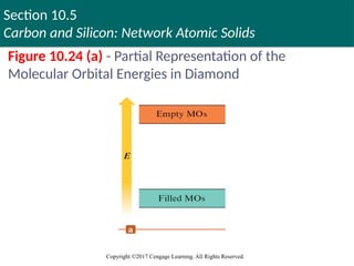
Figure 10.24 (a) - Partial Representation of the
Molecular Orbital Energies in Diamond
Copyright © Cengage Learning. All rights reserved 78
79. Section 10.5
Carbon and Silicon: Network Atomic Solids
Copyright ©2017 Cengage Learning. All Rights Reserved.
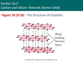
Graphite
Slippery, black, and a conductor of heat and
electricity
Structure is based on layers of carbon atoms
arranged in fused six-membered rings
Each carbon atom in a layer is surrounded by three
other carbon atoms in a trigonal planar arrangement
with 120-degree bond angles
80. Section 10.5
Carbon and Silicon: Network Atomic Solids
Copyright ©2017 Cengage Learning. All Rights Reserved.
Graphite (Continued)
sp2
hybridization is predicted by the localized
electron model
Three sp2
orbitals on each carbon atom form σ bonds
with three other carbon atoms
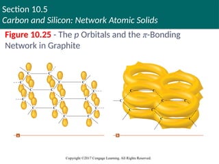
One 2p orbital on each carbon remains unhybridized
and is perpendicular to the plane
Used as a lubricant in locks
Slipperiness is due to the strong bonding within the
layers of carbon atoms rather than between the layers
81. Section 10.5
Carbon and Silicon: Network Atomic Solids
Copyright ©2017 Cengage Learning. All Rights Reserved.
Figure 10.23 (b) - The Structure of Graphite
82. Section 10.5
Carbon and Silicon: Network Atomic Solids
Copyright ©2017 Cengage Learning. All Rights Reserved.
Figure 10.25 - The p Orbitals and the π-Bonding
Network in Graphite
83. Section 10.5
Carbon and Silicon: Network Atomic Solids
Copyright ©2017 Cengage Learning. All Rights Reserved.
Silicon
An important constituent of the compounds that
form the earth’s crust
Stable silicon compounds involve chains with
silicon–oxygen bonds
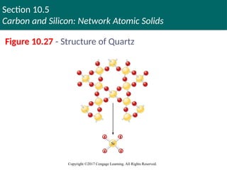
Silica (SiO2): Fundamental silicon–oxygen compound
Structure
Silicon atom satisfies the octet rule by forming single
bonds with four oxygen atoms
84. Section 10.5
Carbon and Silicon: Network Atomic Solids
Copyright ©2017 Cengage Learning. All Rights Reserved.
Figure 10.27 - Structure of Quartz
85. Section 10.5
Carbon and Silicon: Network Atomic Solids
Copyright ©2017 Cengage Learning. All Rights Reserved.
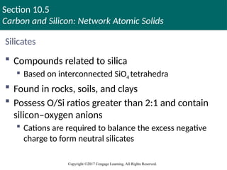
Silicates
Compounds related to silica
Based on interconnected SiO4 tetrahedra
Found in rocks, soils, and clays
Possess O/Si ratios greater than 2:1 and contain
silicon–oxygen anions
Cations are required to balance the excess negative
charge to form neutral silicates
86. Section 10.5
Carbon and Silicon: Network Atomic Solids
Copyright ©2017 Cengage Learning. All Rights Reserved.
Silicates (Continued)
Glass: Amorphous solid that is formed when silica
is heated above 1600°C and cooled rapidly
Homogeneous, noncrystalline frozen solution
Common glass results when substances, such as
Na2CO3, are added to the silica melt and then cooled
Properties vary based on the additives
87. Section 10.5
Carbon and Silicon: Network Atomic Solids
Copyright ©2017 Cengage Learning. All Rights Reserved.
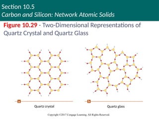
Figure 10.29 - Two-Dimensional Representations of
Quartz Crystal and Quartz Glass
Quartz crystal Quartz glass
88. Section 10.5
Carbon and Silicon: Network Atomic Solids
Copyright ©2017 Cengage Learning. All Rights Reserved.
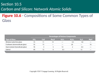
Figure 10.6 - Compositions of Some Common Types of
Glass
89. Section 10.5
Carbon and Silicon: Network Atomic Solids
Copyright ©2017 Cengage Learning. All Rights Reserved.
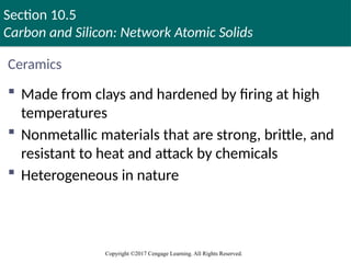
Ceramics
Made from clays and hardened by firing at high
temperatures
Nonmetallic materials that are strong, brittle, and
resistant to heat and attack by chemicals
Heterogeneous in nature
Copyright © Cengage Learning. All rights reserved 89
90. Section 10.5
Carbon and Silicon: Network Atomic Solids
Copyright ©2017 Cengage Learning. All Rights Reserved.
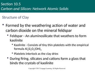
Structure of Clay
Formed by the weathering action of water and
carbon dioxide on the mineral feldspar
Feldspar - An aluminosilicate that weathers to form
kaolinite
Kaolinite - Consists of tiny thin platelets with the empirical
formula Al2Si2O5(OH)4
Platelets interlock as the clay dries
During firing, silicates and cations form a glass that
binds the crystals of kaolinite
Copyright © Cengage Learning. All rights reserved 90
91. Section 10.5
Carbon and Silicon: Network Atomic Solids
Copyright ©2017 Cengage Learning. All Rights Reserved.
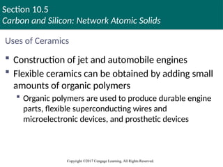
Uses of Ceramics
Construction of jet and automobile engines
Flexible ceramics can be obtained by adding small
amounts of organic polymers
Organic polymers are used to produce durable engine
parts, flexible superconducting wires and
microelectronic devices, and prosthetic devices
92. Section 10.5
Carbon and Silicon: Network Atomic Solids
Copyright ©2017 Cengage Learning. All Rights Reserved.
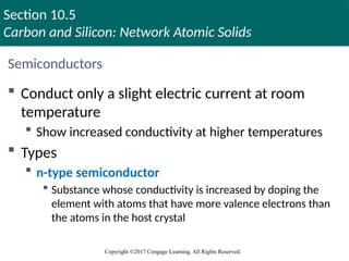
Semiconductors
Conduct only a slight electric current at room
temperature
Show increased conductivity at higher temperatures
Types
n-type semiconductor
Substance whose conductivity is increased by doping the
element with atoms that have more valence electrons than
the atoms in the host crystal
Copyright © Cengage Learning. All rights reserved 92
93. Section 10.5
Carbon and Silicon: Network Atomic Solids
Copyright ©2017 Cengage Learning. All Rights Reserved.
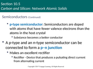
Semiconductors (Continued)
p-type semiconductor: Semiconductors are doped
with atoms that have fewer valence electrons than the
atoms in the host crystal
Substance becomes a better conductor
A p-type and an n-type semiconductor can be
connected to form a p–n junction
Makes an excellent rectifier
Rectifier - Device that produces a pulsating direct current
from alternating current
94. Section 10.5
Carbon and Silicon: Network Atomic Solids
Copyright ©2017 Cengage Learning. All Rights Reserved.
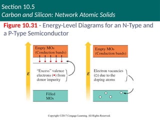
Figure 10.31 - Energy-Level Diagrams for an N-Type and
a P-Type Semiconductor
Copyright © Cengage Learning. All rights reserved 94
95. Section 10.5
Carbon and Silicon: Network Atomic Solids
Copyright ©2017 Cengage Learning. All Rights Reserved.
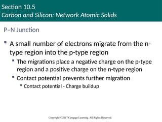
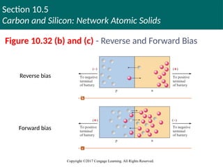
P–N Junction
A small number of electrons migrate from the n-
type region into the p-type region
The migrations place a negative charge on the p-type
region and a positive charge on the n-type region
Contact potential prevents further migration
Contact potential - Charge buildup
96. Section 10.5
Carbon and Silicon: Network Atomic Solids
Copyright ©2017 Cengage Learning. All Rights Reserved.
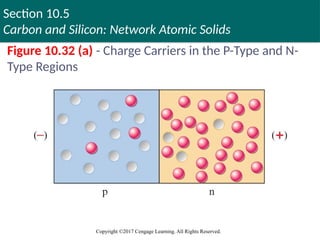
Figure 10.32 (a) - Charge Carriers in the P-Type and N-
Type Regions
97. Section 10.5
Carbon and Silicon: Network Atomic Solids
Copyright ©2017 Cengage Learning. All Rights Reserved.
Figure 10.32 (b) and (c) - Reverse and Forward Bias
Reverse bias
Forward bias
98. Section 10.6
Molecular Solids
Copyright ©2017 Cengage Learning. All Rights Reserved.
Molecular Solids
Characterized by strong covalent bonding within
molecules and weak bonding between molecules
Intermolecular forces depend on the nature of the
molecules
Molecules that do not have a dipole moment possess
London dispersion forces
Molecules with dipole moments have greater
intermolecular forces when hydrogen bonding is
possible
99. Section 10.7
Ionic Solids
Copyright ©2017 Cengage Learning. All Rights Reserved.
Ionic Solids
Stable, high-melting substances held together by
the strong electrostatic forces that exist between
oppositely charged ions
Structure of binary ionic solids can be explained
by closest packing of spheres
Spheres are packed to:
Maximize electrostatic attractions among oppositely charged
ions
Minimize repulsions among ions with like charges
Copyright © Cengage Learning. All rights reserved 99
100. Section 10.7
Ionic Solids
Copyright ©2017 Cengage Learning. All Rights Reserved.
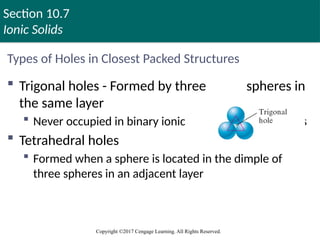
Types of Holes in Closest Packed Structures
Trigonal holes - Formed by three spheres in
the same layer
Never occupied in binary ionic compounds
Tetrahedral holes
Formed when a sphere is located in the dimple of
three spheres in an adjacent layer
101. Section 10.7
Ionic Solids
Copyright ©2017 Cengage Learning. All Rights Reserved.
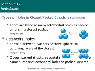
Types of Holes in Closest Packed Structures (Continued)
There are twice as many tetrahedral holes as packed
anions in a closest packed
structure
Octahedral holes
Formed between two sets of three spheres in
adjoining layers of the closest packed
structures
Closest packed structures contain the
same number of octahedral holes as packed spheres
102. Section 10.7
Ionic Solids
Copyright ©2017 Cengage Learning. All Rights Reserved.
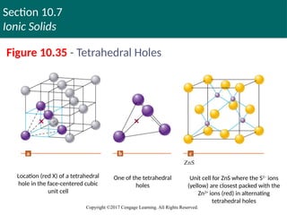
Figure 10.35 - Tetrahedral Holes
Location (red X) of a tetrahedral
hole in the face-centered cubic
unit cell
One of the tetrahedral
holes
Unit cell for ZnS where the S2–
ions
(yellow) are closest packed with the
Zn2+
ions (red) in alternating
tetrahedral holes
103. Section 10.7
Ionic Solids
Copyright ©2017 Cengage Learning. All Rights Reserved.
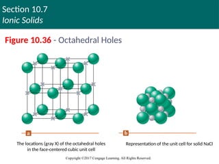
Figure 10.36 - Octahedral Holes
The locations (gray X) of the octahedral holes
in the face-centered cubic unit cell
Representation of the unit cell for solid NaCl
104. Section 10.7
Ionic Solids
Copyright ©2017 Cengage Learning. All Rights Reserved.
Interactive Example 10.3 - Determining the Number of
Ions in a Unit Cell
Determine the net number of Na+
and Cl–
ions in
the sodium chloride unit cell
105. Section 10.7
Ionic Solids
Copyright ©2017 Cengage Learning. All Rights Reserved.
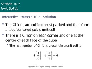
Interactive Example 10.3 - Solution
The Cl–
ions are cubic closest packed and thus form
a face-centered cubic unit cell
There is a Cl–
ion on each corner and one at the
center of each face of the cube
The net number of Cl–
ions present in a unit cell is
1 1
8 + 6 = 4
8 2
106. Section 10.7
Ionic Solids
Copyright ©2017 Cengage Learning. All Rights Reserved.
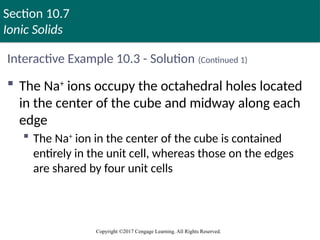
Interactive Example 10.3 - Solution (Continued 1)
The Na+
ions occupy the octahedral holes located
in the center of the cube and midway along each
edge
The Na+
ion in the center of the cube is contained
entirely in the unit cell, whereas those on the edges
are shared by four unit cells
107. Section 10.7
Ionic Solids
Copyright ©2017 Cengage Learning. All Rights Reserved.
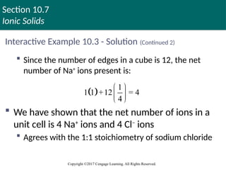
Interactive Example 10.3 - Solution (Continued 2)
Since the number of edges in a cube is 12, the net
number of Na+
ions present is:
We have shown that the net number of ions in a
unit cell is 4 Na+
ions and 4 Cl–
ions
Agrees with the 1:1 stoichiometry of sodium chloride
1
1 1 +12 = 4
4
108. Section 10.7
Ionic Solids
Copyright ©2017 Cengage Learning. All Rights Reserved.
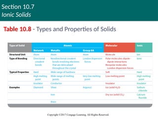
Table 10.8 - Types and Properties of Solids
Copyright © Cengage Learning. All rights reserved 108
109. Section 10.7
Ionic Solids
Copyright ©2017 Cengage Learning. All Rights Reserved.
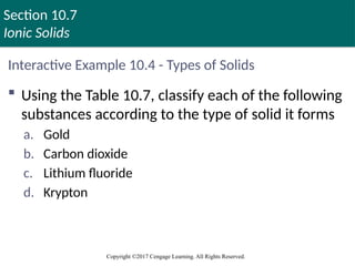
Interactive Example 10.4 - Types of Solids
Using the Table 10.7, classify each of the following
substances according to the type of solid it forms
a. Gold
b. Carbon dioxide
c. Lithium fluoride
d. Krypton
110. Section 10.7
Ionic Solids
Copyright ©2017 Cengage Learning. All Rights Reserved.
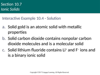
Interactive Example 10.4 - Solution
a. Solid gold is an atomic solid with metallic
properties
b. Solid carbon dioxide contains nonpolar carbon
dioxide molecules and is a molecular solid
c. Solid lithium fluoride contains Li+
and F–
ions and
is a binary ionic solid
111. Section 10.7
Ionic Solids
Copyright ©2017 Cengage Learning. All Rights Reserved.
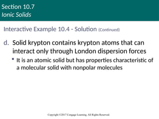
Interactive Example 10.4 - Solution (Continued)
d. Solid krypton contains krypton atoms that can
interact only through London dispersion forces
It is an atomic solid but has properties characteristic of
a molecular solid with nonpolar molecules
112. Section 10.8
Vapor Pressure and Changes of State
Copyright ©2017 Cengage Learning. All Rights Reserved.
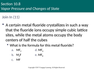
Join In (11)
A certain metal fluoride crystallizes in such a way
that the fluoride ions occupy simple cubic lattice
sites, while the metal atoms occupy the body
centers of half the cubes
What is the formula for this metal fluoride?
a. MF2 d. MF6
b. M2F e. MF8
c. MF
113. Section 10.8
Vapor Pressure and Changes of State
Copyright ©2017 Cengage Learning. All Rights Reserved.
Join In (12)
Which of the following statements is incorrect?
a. Ionic solids generally have high melting points
b. Ionic solids are insulators
c. The binding forces in a molecular solid include
London dispersion forces
d. Molecular solids generally have high melting points
114. Section 10.8
Vapor Pressure and Changes of State
Copyright ©2017 Cengage Learning. All Rights Reserved.
Join In (13)
A certain metal fluoride crystallizes in such a way
that the fluoride ions occupy simple cubic lattice
sites, while the metal ions occupy the body
centers of half the cubes
Which of the following could be the metal ion?
a. The calcium ion d. The vanadium(IV) ion
b. The sodium ion e. Any of these ions
c. The iron(III) ion
115. Section 10.8
Vapor Pressure and Changes of State
Copyright ©2017 Cengage Learning. All Rights Reserved.
Vaporization (Evaporation)
Molecules of a liquid escape the liquid’s surface to
form a gas
Heat of vaporization (ΔHvap ): Energy required to
vaporize 1 mole of a liquid at a pressure of 1 atm
Endothermic in nature
116. Section 10.8
Vapor Pressure and Changes of State
Copyright ©2017 Cengage Learning. All Rights Reserved.
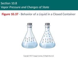
Figure 10.37 - Behavior of a Liquid in a Closed Container
Copyright © Cengage Learning. All rights reserved 116
117. Section 10.8
Vapor Pressure and Changes of State
Copyright ©2017 Cengage Learning. All Rights Reserved.
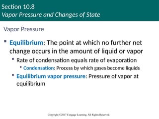
Vapor Pressure
Equilibrium: The point at which no further net
change occurs in the amount of liquid or vapor
Rate of condensation equals rate of evaporation
Condensation: Process by which gases become liquids
Equilibrium vapor pressure: Pressure of vapor at
equilibrium
118. Section 10.8
Vapor Pressure and Changes of State
Copyright ©2017 Cengage Learning. All Rights Reserved.
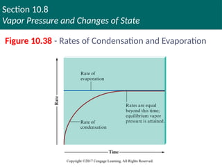
Figure 10.38 - Rates of Condensation and Evaporation
Copyright © Cengage Learning. All rights reserved 118
119. Section 10.8
Vapor Pressure and Changes of State
Copyright ©2017 Cengage Learning. All Rights Reserved.
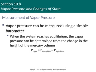
Measurement of Vapor Pressure
Vapor pressure can be measured using a simple
barometer
When the system reaches equilibrium, the vapor
pressure can be determined from the change in the
height of the mercury column
Pvapor = Patmosphere – PHg column
120. Section 10.8
Vapor Pressure and Changes of State
Copyright ©2017 Cengage Learning. All Rights Reserved.
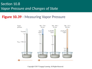
Figure 10.39 - Measuring Vapor Pressure
121. Section 10.8
Vapor Pressure and Changes of State
Copyright ©2017 Cengage Learning. All Rights Reserved.
Critical Thinking
You have seen that the water molecule has a bent
shape and therefore is a polar molecule
This accounts for many of water’s interesting
properties
What if the water molecule was linear?
How would this affect the properties of water, such as its
surface tension, heat of vaporization, and vapor pressure?
How would life be different?
122. Section 10.8
Vapor Pressure and Changes of State
Copyright ©2017 Cengage Learning. All Rights Reserved.
Vapor Pressure and Liquids
Liquids with high vapor pressures are volatile
Evaporation occurs rapidly in an open environment
The size of the intermolecular forces in a liquid
determines its vapor pressure
Substances with large molar masses have relatively
low vapor pressures
123. Section 10.8
Vapor Pressure and Changes of State
Copyright ©2017 Cengage Learning. All Rights Reserved.
Vapor Pressure and Liquids (Continued)
Vapor pressure increases significantly with
temperature
A molecule must have sufficient kinetic energy to
overcome intermolecular forces
124. Section 10.8
Vapor Pressure and Changes of State
Copyright ©2017 Cengage Learning. All Rights Reserved.
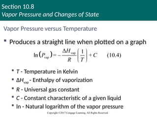
Vapor Pressure versus Temperature
Produces a straight line when plotted on a graph
T - Temperature in Kelvin
ΔHvap - Enthalpy of vaporization
R - Universal gas constant
C - Constant characteristic of a given liquid
ln - Natural logarithm of the vapor pressure
vap
vap
Δ 1
ln = – + (10.4)
H
P C
R T
125. Section 10.8
Vapor Pressure and Changes of State
Copyright ©2017 Cengage Learning. All Rights Reserved.
Vapor Pressure versus Temperature (Continued)
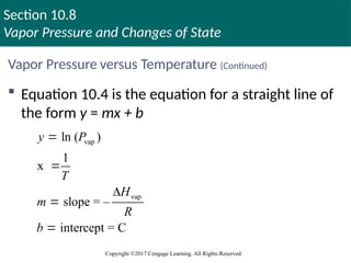
Equation 10.4 is the equation for a straight line of
the form y = mx + b
vap
vap
ln ( )
1
x
slope = –
intercept = C
y P
T
H
m
R
b
126. Section 10.8
Vapor Pressure and Changes of State
Copyright ©2017 Cengage Learning. All Rights Reserved.
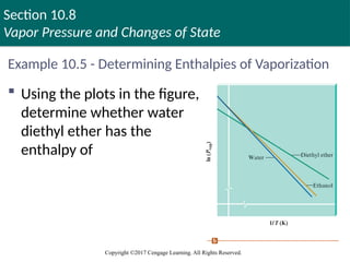
Example 10.5 - Determining Enthalpies of Vaporization
Using the plots in the figure,
determine whether water or
diethyl ether has the larger
enthalpy of vaporization
127. Section 10.8
Vapor Pressure and Changes of State
Copyright ©2017 Cengage Learning. All Rights Reserved.
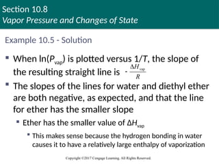
Example 10.5 - Solution
When ln(Pvap) is plotted versus 1/T, the slope of
the resulting straight line is
The slopes of the lines for water and diethyl ether
are both negative, as expected, and that the line
for ether has the smaller slope
Ether has the smaller value of ΔHvap
This makes sense because the hydrogen bonding in water
causes it to have a relatively large enthalpy of vaporization
vap
H
R
128. Section 10.8
Vapor Pressure and Changes of State
Copyright ©2017 Cengage Learning. All Rights Reserved.
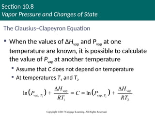
The Clausius–Clapeyron Equation
When the values of ΔHvap and Pvap at one
temperature are known, it is possible to calculate
the value of Pvap at another temperature
Assume that C does not depend on temperature
At temperatures T1 and T2
1 2
vap vap
vap, vap,
1 2
ln + = = ln +
T T
H H
P C P
RT RT
129. Section 10.8
Vapor Pressure and Changes of State
Copyright ©2017 Cengage Learning. All Rights Reserved.
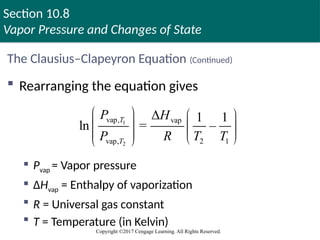
The Clausius–Clapeyron Equation (Continued)
Rearranging the equation gives
Pvap = Vapor pressure
ΔHvap = Enthalpy of vaporization
R = Universal gas constant
T = Temperature (in Kelvin)
1
2
vap, vap
vap, 2 1
Δ 1 1
ln = –
T
T
P H
P R T T
Copyright © Cengage Learning. All rights reserved 129
130. Section 10.8
Vapor Pressure and Changes of State
Copyright ©2017 Cengage Learning. All Rights Reserved.
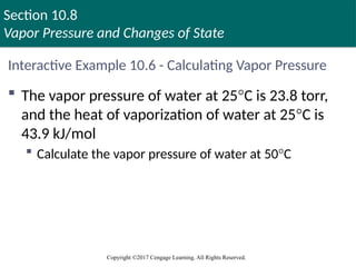
Interactive Example 10.6 - Calculating Vapor Pressure
The vapor pressure of water at 25°C is 23.8 torr,
and the heat of vaporization of water at 25°C is
43.9 kJ/mol
Calculate the vapor pressure of water at 50°C
131. Section 10.8
Vapor Pressure and Changes of State
Copyright ©2017 Cengage Learning. All Rights Reserved.
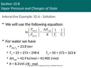
Interactive Example 10.6 - Solution
We will use the following equation:
For water we have
Pvap,T1
= 23.8 torr
T1 = 25 + 273 = 298 K T2 = 50 + 273 = 323 K
ΔHvap = 43.9 kJ/mol = 43,900 J/mol
R = 8.3145 J/K · mol
1
2
vap, vap
vap, 2 1
Δ 1 1
ln = –
T
T
P H
P R T T
132. Section 10.8
Vapor Pressure and Changes of State
Copyright ©2017 Cengage Learning. All Rights Reserved.
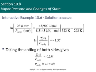
Interactive Example 10.6 - Solution (Continued)
Taking the antilog of both sides gives
2
vap,
23.8 torr 43,900 J/mol 1 1
ln = –
(torr) 8.3145 J/K mol 323 K 298 K
T
P
2
vap,
23.8
ln = 1.37
T
P
2
2
vap,
vap,
23.8
= 0.254
93.7 torr
T
T
P
P
133. Section 10.8
Vapor Pressure and Changes of State
Copyright ©2017 Cengage Learning. All Rights Reserved.
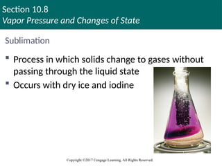
Sublimation
Process in which solids change to gases without
passing through the liquid state
Occurs with dry ice and iodine
134. Section 10.8
Vapor Pressure and Changes of State
Copyright ©2017 Cengage Learning. All Rights Reserved.
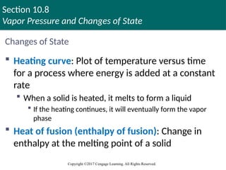
Changes of State
Heating curve: Plot of temperature versus time
for a process where energy is added at a constant
rate
When a solid is heated, it melts to form a liquid
If the heating continues, it will eventually form the vapor
phase
Heat of fusion (enthalpy of fusion): Change in
enthalpy at the melting point of a solid
135. Section 10.8
Vapor Pressure and Changes of State
Copyright ©2017 Cengage Learning. All Rights Reserved.
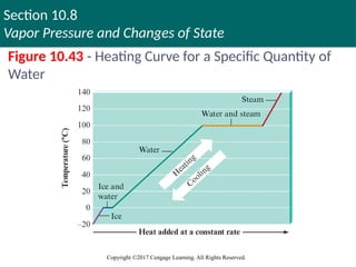
Figure 10.43 - Heating Curve for a Specific Quantity of
Water
136. Section 10.8
Vapor Pressure and Changes of State
Copyright ©2017 Cengage Learning. All Rights Reserved.
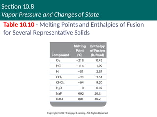
Table 10.10 - Melting Points and Enthalpies of Fusion
for Several Representative Solids
137. Section 10.8
Vapor Pressure and Changes of State
Copyright ©2017 Cengage Learning. All Rights Reserved.
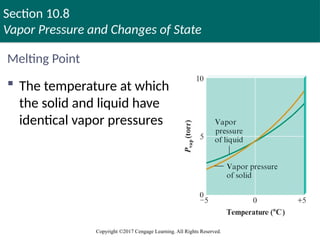
Melting Point
The temperature at which
the solid and liquid have
identical vapor pressures
138. Section 10.8
Vapor Pressure and Changes of State
Copyright ©2017 Cengage Learning. All Rights Reserved.
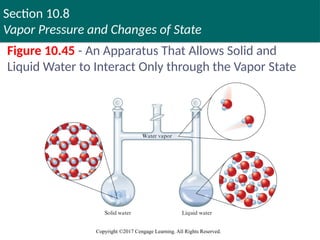
Figure 10.45 - An Apparatus That Allows Solid and
Liquid Water to Interact Only through the Vapor State
139. Section 10.8
Vapor Pressure and Changes of State
Copyright ©2017 Cengage Learning. All Rights Reserved.
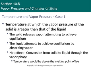
Temperature and Vapor Pressure - Case 1
Temperature at which the vapor pressure of the
solid is greater than that of the liquid
The solid releases vapor, attempting to achieve
equilibrium
The liquid attempts to achieve equilibrium by
absorbing vapor
Net effect - Conversion from solid to liquid through the
vapor phase
Temperature would be above the melting point of ice
140. Section 10.8
Vapor Pressure and Changes of State
Copyright ©2017 Cengage Learning. All Rights Reserved.
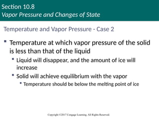
Temperature and Vapor Pressure - Case 2
Temperature at which vapor pressure of the solid
is less than that of the liquid
Liquid will disappear, and the amount of ice will
increase
Solid will achieve equilibrium with the vapor
Temperature should be below the melting point of ice
141. Section 10.8
Vapor Pressure and Changes of State
Copyright ©2017 Cengage Learning. All Rights Reserved.
Temperature and Vapor Pressure - Case 3
Temperature at which the vapor pressures of the
solid and liquid are identical
Coexist in the apparatus at equilibrium with the vapor
Normal melting point: Temperature at which the
vapor pressures of the solid and liquid states are
identical at 1 atmosphere of pressure
Represents the freezing point that enables existence of solid
and liquid states
142. Section 10.8
Vapor Pressure and Changes of State
Copyright ©2017 Cengage Learning. All Rights Reserved.
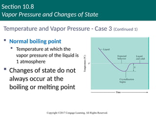
Temperature and Vapor Pressure - Case 3 (Continued 1)
Normal boiling point
Temperature at which the
vapor pressure of the liquid is
1 atmosphere
Changes of state do not
always occur at the
boiling or melting point
143. Section 10.8
Vapor Pressure and Changes of State
Copyright ©2017 Cengage Learning. All Rights Reserved.
Temperature and Vapor Pressure - Case 3 (Continued 2)
Supercooled water remains in the liquid state below
0°C and 1 atm of pressure
Water can be superheated if it is heated rapidly
Vapor pressure in the liquid is greater than atmospheric
pressure
Bubbles formed burst before reaching the surface, resulting
in bumping
144. Section 10.8
Vapor Pressure and Changes of State
Copyright ©2017 Cengage Learning. All Rights Reserved.
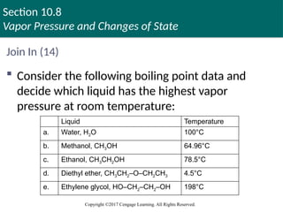
Join In (14)
Consider the following boiling point data and
decide which liquid has the highest vapor
pressure at room temperature:
Liquid Temperature
a. Water, H2O 100°C
b. Methanol, CH3OH 64.96°C
c. Ethanol, CH3CH2OH 78.5°C
d. Diethyl ether, CH3CH2–O–CH2CH3 4.5°C
e. Ethylene glycol, HO–CH2–CH2–OH 198°C
145. Section 10.8
Vapor Pressure and Changes of State
Copyright ©2017 Cengage Learning. All Rights Reserved.
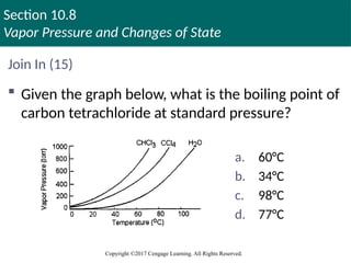
Join In (15)
Given the graph below, what is the boiling point of
carbon tetrachloride at standard pressure?
a. 60°C
b. 34°C
c. 98°C
d. 77°C
146. Section 10.8
Vapor Pressure and Changes of State
Copyright ©2017 Cengage Learning. All Rights Reserved.
Join In (16)
Which of the following would you expect to have
the lowest vapor pressure?
a. CH3OCH3
b. CH3CH2OH
c. CH3CH2CH3
d. CH3CH2CH2CH3
e. H2O
147. Section 10.8
Vapor Pressure and Changes of State
Copyright ©2017 Cengage Learning. All Rights Reserved.
Join In (17)
What is the vapor pressure of water at 70°C?
a. 5.00 atm
b. 1.20 atm
c. 1.00 atm
d. 0.31 atm
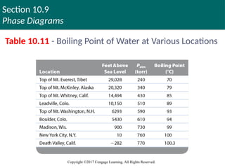
148. Section 10.9
Phase Diagrams
Copyright ©2017 Cengage Learning. All Rights Reserved.
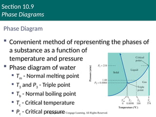
Phase Diagram
Convenient method of representing the phases of
a substance as a function of
temperature and pressure
Phase diagram of water
Tm - Normal melting point
T3 and P3 - Triple point
Tb - Normal boiling point
Tc - Critical temperature
Pc - Critical pressure
Copyright © Cengage Learning. All rights reserved 148
149. Section 10.9
Phase Diagrams
Copyright ©2017 Cengage Learning. All Rights Reserved.
Phase Diagram (Continued)
Triple point: Temperature at which all three
phases exist simultaneously
Critical point: Defined by critical pressure and
temperature
Critical pressure: Pressure required to produce
liquefaction at the critical temperature
Critical temperature: The temperature above which
vapor cannot be liquefied, irrespective of the
pressure applied
Copyright © Cengage Learning. All rights reserved 149
150. Section 10.9
Phase Diagrams
Copyright ©2017 Cengage Learning. All Rights Reserved.
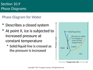
Phase Diagram for Water
Describes a closed system
At point X, ice is subjected to
increased pressure at
constant temperature
Solid/liquid line is crossed as
the pressure is increased
151. Section 10.9
Phase Diagrams
Copyright ©2017 Cengage Learning. All Rights Reserved.
Phase Diagram for Water - Observations
The solid/liquid boundary line has a negative
slope
At the melting point, liquid and solid are in
dynamic equilibrium
When pressure is applied, the volume is reduced
A given mass of ice has more volume at 0°C than the
same mass of water in liquid state
Freezing point of water is less than 0°C when external
pressure is greater than 1 atm
152. Section 10.9
Phase Diagrams
Copyright ©2017 Cengage Learning. All Rights Reserved.
Phase Diagram for Water - Applications
Ice skating
Narrow blades of skates exert a large amount of
pressure
Frictional heat caused when skates moves over ice
contributes to further melting of ice
As the blades pass by, the liquid refreezes
Low density of ice
Causes ice formed on rivers and lakes to float and this
helps prevent water bodies from freezing in the winter
153. 154. Section 10.9
Phase Diagrams
Copyright ©2017 Cengage Learning. All Rights Reserved.
Critical Thinking
Ice is less dense than liquid water, as evidenced by
the fact that ice floats in a glass of water
What if ice was more dense than liquid water?
How would this affect the phase diagram for water?
155. Section 10.9
Phase Diagrams
Copyright ©2017 Cengage Learning. All Rights Reserved.
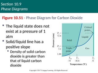
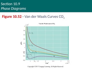
Figure 10.51 - Phase Diagram for Carbon Dioxide
The liquid state does not
exist at a pressure of 1
atm
Solid/liquid line has a
positive slope
Density of solid carbon
dioxide is greater than
that of liquid carbon
dioxide
156. Section 10.9
Phase Diagrams
Copyright ©2017 Cengage Learning. All Rights Reserved.
Phase Diagram for Carbon Dioxide - Applications
Carbon dioxide is used in fire extinguishers
Liquid released from the extinguisher into the
environment at 1 atm immediately changes to a vapor
Dry ice
A convenient refrigerant as it does not undergo the
liquid phase under normal atmospheric conditions
157. Section 10.9
Phase Diagrams
Copyright ©2017 Cengage Learning. All Rights Reserved.
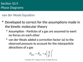
van der Waals Equation
Developed to correct for the assumptions made in
the kinetic molecular theory
Assumption - Particles of a gas are assumed to exert
no forces on each other
van der Waals added a correction factor (a) to the
observed pressure to account for the interparticle
attractions of a gas
2
ideal obs
= +
n
P P a
V
158. Editor's Notes #21 Correct answer
London dispersion forces
Noble gases are nonpolar, so their only intermolecular forces are London dispersion forces
#22 Correct answer
None of these statements is correct
Both molecules are nonpolar (both are tetrahedral)
Since CCl4 has more electrons than CH4, its London forces are stronger; so CCl4 is a liquid, while CH4 is a gas
#23 Correct answer
H2O
Water exhibits hydrogen bonding
Methane (CH4), N2, and He exhibit London dispersion forces
Carbon monoxide (CO) exhibits dipole–dipole attraction
#24 Correct answer
London dispersion forces
Methane is a nonpolar molecule (it has a tetrahedral geometry and shape), so it exhibits London dispersion forces
#26 Correct answer
A hydrogen atom from one water molecule and an oxygen atom from the other water molecule
The hydrogen–oxygen chemical bond is quite polar, leaving the hydrogen with a partial positive charge and the oxygen with a partial negative charge
Thus the hydrogen from one water molecule has an attraction to the oxygen of the other water molecule
#27 Correct answer
Na2S
The highest boiling point should result from an ionic compound with ion–ion forces of attraction
The only ionic compound in these choices is Na2S
#28 Correct answer
Hydrogen bonding
Hydrogen bonds are the strongest owing to the great polarity of the bond and the close approach of the dipoles
#29 Correct answer
CH4
The lowest boiling point should result from the species with the weakest intermolecular forces
Of the species given here, CH4 has the weakest London dispersion forces and is the smallest in size
#30 Correct answer
Ne < C2H6 < CH3OH
The boiling points are determined by size and intermolecular forces
Ne has the lowest boiling point because it is the smallest and has only London dispersion forces
C2H6 is next; it has only London dispersion forces
CH3OH is next; it has hydrogen bonding
#38 Correct answer
The surface tension and viscosity of liquid A are greater than those of liquid B
As the strength of intermolecular forces increases, both surface tension (a measure of a liquid’s resistance to an increase in its surface area) and viscosity (a measure of a liquid’s resistance to flow) generally increase
#112 Correct answer
MF2
Since the fluoride ions occupy simple cubic lattice sites and the metal (M) ions occupy half of the body-centered sites, the formula would be M½F or MF2
#113 Correct answer
Molecular solids generally have high melting points
Molecular solids exhibit London dispersion forces, which indicate that they have low melting points
Ionic solids exhibit ionic forces, which indicate that they have high melting points and have the ability to be insulators
If the ionic compounds are molten, they are conductors
#114 Correct answer
The calcium ion
Each unit cell contains one F– ion
Because the metal ions are in half the unit cells, the metal ion must have a 2+ charge
The only choice with a 2+ charge is the calcium ion
#144 Correct answer
Diethyl ether, CH3CH2–O–CH2CH3
The substance with the lowest boiling point should have the highest vapor pressure at room temperature
#145 Correct answer
77°C
According to the graph, at 760 torr vapor pressure the temperature of CCl4 is 77°C, which is its boiling point
#146 Correct answer
H2O
Water exhibits hydrogen bonding, as does ethanol (choice b)
However, there are two hydrogen atoms on water that can hydrogen-bond to other water molecules
Because the intermolecular forces exhibited by water are greater than the intermolecular forces for the other choices, its vapor pressure would be the lowest
#147 Correct answer
0.31 atm
The normal boiling point of water (i.e., the temperature at which water boils at 1 atm) is 100°C, so the vapor pressure of water at 100°C is 1 atm
Because vapor pressure increases with increasing temperature, the vapor pressure at 70°C must be less than 1 atm
Only one choice (0.31 atm) is less than 1 atm