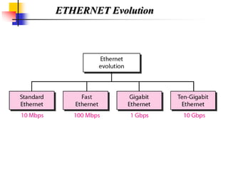
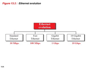
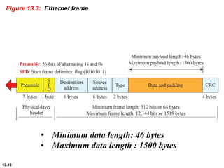
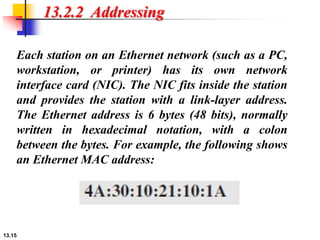
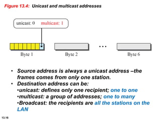
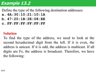
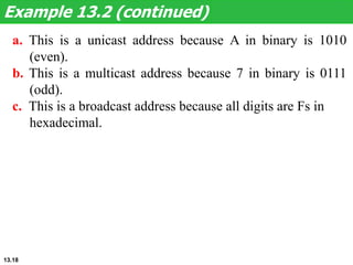
Chapter 13
Wired LANs: Ethernet
Copyright © The McGraw-Hill Companies, Inc. Permission required for reproduction or display.
Chapter 5: Outline
13.1 ETHERNET PROTOCOL
13.2 STANDARD ETHERNET
13.3 FAST ETHERNET
13.4 GIGABIT ETHERNET
13.5 10 GIGABIT ETHERNET
13.3
13-1 ETHERNET PROTOCOL
The data-link layer and the physical
layer are the territory of the local and
wide area networks. This means that
when we discuss these two layers, we
are talking about networks that are
using them.
13.4
13.13.1 IEEE Project 802
In 1985, the Computer Society of the IEEE started a
project, called Project 802, to set standards to enable
intercommunication among equipment from a
variety of manufacturers. Project 802 does not seek
to replace any part of the OSI model or TCP/IP
protocol suite. Instead, it is a way of specifying
functions of the physical layer and the data-link
layer of major LAN protocols. The relationship of
the 802 Standard to the TCP/IP protocol suite is
shown in Figure 13.13.
13.13.1 IEEE Project 802
IEEE divided the Data link layer into two
sublayer:
 upper layer : logical link control (LLC);
flow and error control.
 Lower sublayer : Multiple access (MAC);
media access control.
 Multiple access (MAC) :for resolving
access to the shared media.
 If channel is dedicated ( point to point)
we do not need the (MAC); sublayer.
13.6
Figure 13.1: IEEE standard for LANs
LLC (Logical link control)and MAC (Media Access
Control)
 In IEEE project 802, flow control , error control, and
part of the framing duties are collected into one
sublayer called the logical link control (LLC )
 LLC provides one single data link control for all
IEEE LANs.
 IEEE project 802 has created a sublayerMAC that
defines the specific access method for each LAN. In
contrast to the LLC, MAC contains a number of
distinct modules: each defines the access method
and the framing format specific to the
corresponding LAN protocol
For example:
• CSMA/CD as media access method for Ethernet
LANs.
• Token passing method for Token Ring and Token
ETHERNET Evolution
13.9
Figure 13.2 : Ethernet evolution
13.10
13-2 STANDARD ETHERNET
We refer to the original Ethernet
technology with the data rate of 10 Mbps
as the Standard Ethernet. Although most
implementations have moved to other
technologies in the Ethernet evolution,
there are some features of the Standard
Ethernet that have not changed during
the evolution. We discuss this standard
version first.
13.11
13.2.1 Characteristics
Let us first discuss some characteristics of the Standard
Ethernet.
• Connectionless and unreliable service
• Frame format:
• Frame length:
• Minimum: 64 bytes (512 bits)
• Maximum: 1518 bytes (12,144 bits)
13.12
Frame format
The Ethernet frame contains seven fields:
• Preamble: 7bytes (56 bits); Alternating 0s and 1s,
used for synchronizing
• Start Frame Delimiter (SFD): 10101011 indicates the
start of the frame. Last two bits (11) alerts that the
next field is destination address.
• preamble and SFD are added at the physical layer and
is not formally part of the frame
• Destination Address (DA): Destination address
• Source Address (SA): Source Address
• Type: Define the upper-layer protocol using the MAC
frame. OR define the number of bytes in the data
filed.
• Data: minumum: 46 and maximum : 1500 bytes
• CRC: error detection information:CRC-32
13.13
Figure 13.3: Ethernet frame
• Minimum data length: 46 bytes
• Maximum data length : 1500 bytes
Show how the address 47:20:1B:2E:08:EE is sent out
online.
Solution
The address is sent left to right, byte by byte; for each byte,
it is sent right to left, bit by bit, as shown below:
Example 13.1
13.14
13.15
13.2.2 Addressing
Each station on an Ethernet network (such as a PC,
workstation, or printer) has its own network
interface card (NIC). The NIC fits inside the station
and provides the station with a link-layer address.
The Ethernet address is 6 bytes (48 bits), normally
written in hexadecimal notation, with a colon
between the bytes. For example, the following shows
an Ethernet MAC address:
13.16
Figure 13.4: Unicast and multicast addresses
• Source address is always a unicast address –the
frames comes from only one station.
• Destination address can be:
•unicast: defines only one recipient; one to one
•multicast: a group of addresses; one to many
•Broadcast: the recipients are all the stations on the
LAN
Define the type of the following destination addresses:
a. 4A:30:10:21:10:1A
b. 47:20:1B:2E:08:EE
c. FF:FF:FF:FF:FF:FF
Example 13.2
Solution
To find the type of the address, we need to look at the
second hexadecimal digit from the left. If it is even, the
address is unicast. If it is odd, the address is multicast. If all
digits are Fs, the address is broadcast. Therefore, we have
the following:
13.17
Example 13.2 (continued)
a. This is a unicast address because A in binary is 1010
(even).
b. This is a multicast address because 7 in binary is 0111
(odd).
c. This is a broadcast address because all digits are Fs in
hexadecimal.
13.18

wired Lans ethernet in routing and switching

  • 1.
    Chapter 13 Wired LANs:Ethernet Copyright © The McGraw-Hill Companies, Inc. Permission required for reproduction or display.
  • 2.
    Chapter 5: Outline 13.1ETHERNET PROTOCOL 13.2 STANDARD ETHERNET 13.3 FAST ETHERNET 13.4 GIGABIT ETHERNET 13.5 10 GIGABIT ETHERNET
  • 3.
    13.3 13-1 ETHERNET PROTOCOL Thedata-link layer and the physical layer are the territory of the local and wide area networks. This means that when we discuss these two layers, we are talking about networks that are using them.
  • 4.
    13.4 13.13.1 IEEE Project802 In 1985, the Computer Society of the IEEE started a project, called Project 802, to set standards to enable intercommunication among equipment from a variety of manufacturers. Project 802 does not seek to replace any part of the OSI model or TCP/IP protocol suite. Instead, it is a way of specifying functions of the physical layer and the data-link layer of major LAN protocols. The relationship of the 802 Standard to the TCP/IP protocol suite is shown in Figure 13.13.
  • 5.
    13.13.1 IEEE Project802 IEEE divided the Data link layer into two sublayer:  upper layer : logical link control (LLC); flow and error control.  Lower sublayer : Multiple access (MAC); media access control.  Multiple access (MAC) :for resolving access to the shared media.  If channel is dedicated ( point to point) we do not need the (MAC); sublayer.
  • 6.
    13.6 Figure 13.1: IEEEstandard for LANs
  • 7.
    LLC (Logical linkcontrol)and MAC (Media Access Control)  In IEEE project 802, flow control , error control, and part of the framing duties are collected into one sublayer called the logical link control (LLC )  LLC provides one single data link control for all IEEE LANs.  IEEE project 802 has created a sublayerMAC that defines the specific access method for each LAN. In contrast to the LLC, MAC contains a number of distinct modules: each defines the access method and the framing format specific to the corresponding LAN protocol For example: • CSMA/CD as media access method for Ethernet LANs. • Token passing method for Token Ring and Token
  • 8.
  • 9.
    13.9 Figure 13.2 :Ethernet evolution
  • 10.
    13.10 13-2 STANDARD ETHERNET Werefer to the original Ethernet technology with the data rate of 10 Mbps as the Standard Ethernet. Although most implementations have moved to other technologies in the Ethernet evolution, there are some features of the Standard Ethernet that have not changed during the evolution. We discuss this standard version first.
  • 11.
    13.11 13.2.1 Characteristics Let usfirst discuss some characteristics of the Standard Ethernet. • Connectionless and unreliable service • Frame format: • Frame length: • Minimum: 64 bytes (512 bits) • Maximum: 1518 bytes (12,144 bits)
  • 12.
    13.12 Frame format The Ethernetframe contains seven fields: • Preamble: 7bytes (56 bits); Alternating 0s and 1s, used for synchronizing • Start Frame Delimiter (SFD): 10101011 indicates the start of the frame. Last two bits (11) alerts that the next field is destination address. • preamble and SFD are added at the physical layer and is not formally part of the frame • Destination Address (DA): Destination address • Source Address (SA): Source Address • Type: Define the upper-layer protocol using the MAC frame. OR define the number of bytes in the data filed. • Data: minumum: 46 and maximum : 1500 bytes • CRC: error detection information:CRC-32
  • 13.
    13.13 Figure 13.3: Ethernetframe • Minimum data length: 46 bytes • Maximum data length : 1500 bytes
  • 14.
    Show how theaddress 47:20:1B:2E:08:EE is sent out online. Solution The address is sent left to right, byte by byte; for each byte, it is sent right to left, bit by bit, as shown below: Example 13.1 13.14
  • 15.
    13.15 13.2.2 Addressing Each stationon an Ethernet network (such as a PC, workstation, or printer) has its own network interface card (NIC). The NIC fits inside the station and provides the station with a link-layer address. The Ethernet address is 6 bytes (48 bits), normally written in hexadecimal notation, with a colon between the bytes. For example, the following shows an Ethernet MAC address:
  • 16.
    13.16 Figure 13.4: Unicastand multicast addresses • Source address is always a unicast address –the frames comes from only one station. • Destination address can be: •unicast: defines only one recipient; one to one •multicast: a group of addresses; one to many •Broadcast: the recipients are all the stations on the LAN
  • 17.
    Define the typeof the following destination addresses: a. 4A:30:10:21:10:1A b. 47:20:1B:2E:08:EE c. FF:FF:FF:FF:FF:FF Example 13.2 Solution To find the type of the address, we need to look at the second hexadecimal digit from the left. If it is even, the address is unicast. If it is odd, the address is multicast. If all digits are Fs, the address is broadcast. Therefore, we have the following: 13.17
  • 18.
    Example 13.2 (continued) a.This is a unicast address because A in binary is 1010 (even). b. This is a multicast address because 7 in binary is 0111 (odd). c. This is a broadcast address because all digits are Fs in hexadecimal. 13.18