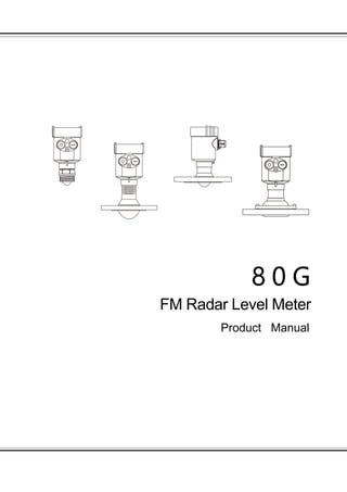
80G FM Radar Level Meter Product Manual

The general principle of the FM continuous wave radar level gauge is that the radar emits electromagnetic waves on the top of the tank, and the electromagnetic waves are received by the radar after being reflected by the medium. The frequency difference δf between the received signal and the transmitted signal is proportional to the distance R from the surface of the medium: R=C (speed)*δf (frequency difference)/2/K (frequency modulation slope). Because the speed of light C and the frequency modulation slope K are known, the frequency difference δf can be estimated to obtain the distance R from the radar installation position to the material surface, and then through the known total height of the tank, subtract the spatial distance from the radar to the material surface (referred to as Empty height) to get the height of the material level.

Recommended
More Related Content
What's hot
Similar to 80G FM Radar Level Meter Product Manual
Similar to 80G FM Radar Level Meter Product Manual (20)
More from Dalian Zero Instrument Technology Co., Ltd China
More from Dalian Zero Instrument Technology Co., Ltd China (20)
Recently uploaded
Recently uploaded (20)
80G FM Radar Level Meter Product Manual
- 1. 8 0 G FM Radar Level Meter Product Manual
- 2. Directory 1、Product Overview.....................................................................1 2、Product Introduction.................................................................3 3、The Installation Requirements..................................................6 4、The Electrical Connection.........................................................12 5、Structure Size........................................................................15 6、Technical Parameters.............................................................18 7、Meter Linearity......................................................................19 8、Product Model Selection.........................................................................21
- 3. 1 80G FM Radar Level Meter Principle: The general principle of the FM continuous wave radar level gauge is that the radar emits electromagnetic waves on the top of the tank, and the electromagnetic waves are received by the radar after being reflected by the medium. The frequency difference δf between the received signal and the transmitted signal is proportional to the distance R from the surface of the medium: R=C (speed)*δf (frequency difference)/2/K (frequency modulation slope). Because the speed of light C and the frequency modulation slope K are known, the frequency difference δf can be estimated to obtain the distance R from the radar installation position to the material surface, and then through the known total height of the tank, subtract the spatial distance from the radar to the material surface (referred to as Empty height) to get the height of the material level.
- 4. 2 Characteristic: 1. Millimeter-wave radar, with a measurement accuracy of up to ±1mm, and a minimum blind area of 0.1m. 2. The smaller antenna size satisfies the measurement of more working conditions. 3. A variety of lens antennas, smaller launch angle, more concentrated energy, stronger echo signal, under the same industrial and mining conditions, compared to Other radar products have higher reliability. 4. With stronger penetrability, it can be used normally even if there is adhesion and condensation. 5. The dynamic signal range is larger, and the measurement of low dielectric constant medium is more stable. 6. A variety of measurement modes, the radar reaction time in the fast measurement mode is less than 1S.
- 5. 3 Product Introducion FMW11S Measuring medium: Liquid Measuring range: 0.1m~10m Process connection: Thread G¾"A / ¾"NPT Flange ≥DN25 Process temperature: -40~100℃ Process pressure: -0.1~1.6 MPa Antenna size:21mm lens antenna Antenna material: PTFE Accuracy: ±5mm Protection level: IP67 Center frequency: 80GHz Launch angle:14° Power source: Two-wire system/DC24V Four-wire system/AC220V Six-wire system/DC12-24V Shell: Aluminum/Plastic/Stainless steel Signal output: Two-wire system/4...20mA/HART protocol Four-wire system/4...20mA/HART protocol Six-wire system/4...20mA/HART protocol FMW11 Measuring medium: Liquid Measuring range: 0.1m~30m Process connection: Thread G½"A /1 ½"NPT Flange ≥DN40 Process temperature: -40~80℃ Process pressure: -0.1~0.3 MPa Antenna size:32mm lens antenna Antenna material: PTFE Accuracy: ±2mm Protection level: IP67 Center frequency: 80GHz Launch angle: 8° Power source: Two-wire system/DC24V Four-wire system/AC220V Six-wire system/DC12-24V Shell: Aluminum/Plastic/Stainless steel Signal output: Two-wire system/4...20mA/HART protocol Four-wire system/4...20mA/HART protocol Six-wire system/4...20mA/HART protocol
- 6. 4 FMW12 Measuring medium: Liquid Measuring range: 0.1m~30m Process connection:Flange ≥DN40 Process temperature: -40~100℃ Process pressure: -0.1~0.3 MPa Antenna size:32mm lens antenna Antenna material: PTFE Accuracy: ±2mm Protection level: IP67 Center frequency: 80GHz Launch angle: 8° Power source: Two-wire system/DC24V Four-wire system/AC220V Six-wire system/DC12-24V Shell: Aluminum/Plastic/Stainless steel Signal output: Two-wire system/4...20mA/HART protocol Four-wire system/4...20mA/HART protocol Six-wire system/4...20mA/HART Protocol FMW13 Measuring medium: Liquid Measuring range: 0.2m~30m/0.3~150m Process connection:Flange ≥DN80 Process temperature: -40~120℃ Process pressure: -0.1~1.0 MPa Antenna size:76mm lens antenna Antenna material: PTFE Accuracy: ±2mm Protection level: IP67 Center frequency: 80GHz Launch angle: 3° Power source: Two-wire system/DC24V Four-wire system/AC220V Six-wire system/DC12-24V Shell: Aluminum/Plastic/Stainless steel Signal output: Two-wire system/4...20mA/HART protocol Four-wire system/4...20mA/HART protocol Six-wire system/4...20mA/HART Protocol
- 7. 5 FMW14 Measuring medium: Liquid Measuring range: 0.1m~30m Process connection:Flange ≥DN50 Process temperature: -40~200℃ Process pressure: -0.1~2.5 MPa Antenna size:44mm lens antenna Antenna material: PTFE Accuracy: ±2mm Protection level: IP67 Center frequency: 80GHz Launch angle: 6° Power source: Two-wire system/DC24V Four-wire system/AC220V Six-wire system/DC12-24V Shell: Aluminum/Plastic/Stainless steel Signal output: Two-wire system/4...20mA/HART protocol Four-wire system/4...20mA/HART protocol Six-wire system/4...20mA/HART protocol FMW15 Measuring medium: Liquid Measuring range: 0.3m~30m Process connection:Flange ≥DN80 Process temperature: -40~200℃ Process pressure: -0.1~2.5 MPa Antenna size:76mm lens antenna Antenna material: PTFE Accuracy: ±2mm Protection level: IP67 Center frequency: 80GHz Launch angle: 3° Power source: Two-wire system/DC24V Four-wire system/AC220V Six-wire system/DC12-24V Shell: Aluminum/Plastic/Stainless steel Signal output: Two-wire system/4...20mA/HART protocol Four-wire system/4...20mA/HART protocol Six-wire system/4...20mA/HART Protocol
- 8. 6 FMW21 Measuring medium: Solid Measuring range: 0.1m~30m/0.3~150m Process connection:Flange ≥DN80 Process temperature: -40~80℃/-40~120℃ Process pressure: -0.1~0.3 MPa Antenna size:76mm lens antenna Antenna material: PTFE Accuracy: ±5mm Protection level: IP67 Center frequency: 80GHz Launch angle: 3° Power source: Two-wire system/DC24V Four-wire system/AC220V Six-wire system/DC12-24V Shell: Aluminum/Plastic/Stainless steel Signal output: Two-wire system/4...20mA/HART protocol Four-wire system/4...20mA/HART protocol Six-wire system/4...20mA/HART protocol FMW Installation requirements: Installation method 1.Threaded installation (applicable to FMW11s, HBRD-FMW11) ≧200mm
- 9. 7 ≧200m 2.Flange installation When using flange mounting, the minimum distance between the meter and the tank wall should be 200mm. Note: ①Datum ②Container center or axis of symmetry 3.Lifting (selected according to specific installation conditions) ≧200mm ≧200mm
- 10. 8 Installation requirements: When installing the instrument, avoid installing it above the material inlet, and try to avoid various objects that affect the signal, such as stirring paddles, etc. Solid measurement Measuring liquid
- 11. 9 Under extremely complex working conditions, the instrument can work normally with the radar installation point as the center and no obstacles in the area with a radius of 20 cm. Schematic diagram of installation and takeover The maximum installation stub height H max depends on the installation stub diameter D and the product launch angle. Long installation and takeover will affect radar performance. FMW11s
- 12. 10 FMW11 FMW12 FMW13
- 13. 11 FMW14 FMW15 FMW21
- 14. 12 Elecitical Connecions Power Supply (4~20) mA(2-wire) The power supply and the output current signal share a two-core shielded cable. See technical data for specific power supply voltage range. (4~20) mA(4/6-wire) The power supply needs to be supplied separately, and the power supply and the current signal use a four-core shielded cable (the current signal and the RS485 interface can be output at the same time, and the output needs to use a six-core shielded cable). Modbus-RS485 The power supply needs to be supplied separately, and the power supply and the digital use a four-core shielded cable (the current signal and the RS485 interface can be output at the same time, and the output needs to use a six-core shielded cable). Connection method 24V two-wire system wiring diagram is as follows:
- 15. 13 Two-wire and two-chamber wiring diagram shown on the side is as follows: Four-wire, two-room wiring diagram: six-wire wiring diagram of the four-wire system is as follows: Supply
- 16. 14 Safety guidance Please observe the requirements of the local electrical installation regulations! Please observe local regulations regarding the health and safety of personnel. All operations on the electrical components of the instrument must be performed by trained professionals. Please check the nameplate of the instrument to ensure that the product specifications meet your requirements. Make sure that the supply voltage is the same as that on the instrument nameplate. Protection level This instrument fully meets the requirements of protection grade IP66/67. Please ensure the waterproof performance of the cable gland. As shown below: How to ensure that the installation meets the requirements of IP67: Make sure the seal head is not damaged. Make sure the cable is not damaged. Make sure that the cable you are using meets the electrical connection specifications. Before entering the electrical interface, bend the cable down to ensure that water does not flow into the housing, see ① Please tighten the cable gland, see ② Please block the unused electrical interface with a blind plug, see ③
- 17. 15 Structure Size: The outer casing size (unit: mm) Aluminum case: Stainless steel case:
- 18. 16 Product Size (unit: mm) FMW11s FMW11
- 19. 17 FMW12 FMW13 FMW14 This date varies with flange size
- 20. 18 FMW15 FMW21 FMW Technical Parameters: Process Connection Flange / material PP, PTFE, stainless steel, stainless steel +PTFE flanging Antenna Material PTFE The outer shell Cast aluminum / stainless steel / plastic ABS The seal between the shell and the shell cover Silicone rubber Casing window Polycarbonate The ground terminal Stainless steel Power supply pressure 2-wire system (single cavity/double cavity) (15-28) V DC
- 21. 19 Power dissipation max 80mA DC24V/ 2W Allowable ripple <100Hz Uss < lV (100~100K) Hz Uss < l0mV 4-wire system (double cavity) (198~242)V AC 110V AC Cable parameter Cable entrance / plug 1 M20×l.5 cable entrance 1 blind plug M20×l.5 Terminal Conductor cross section 2.5mm² Output parameters Output signal (4~20) mA /HART Resolution 1mm Fault signal current output unchanged;20. 5mA;22mA;3.9mA Integration time (0~20)s, adjustable Blind zone 0.1m/0.2m/0.3m Maximum measuring distance 150 m Measurement interval 1 second (depending on parameter settings) Adjustment time about 1 second (depending on parameter settings) Working storage and transportation temperature (-40~80) ℃ Relative humidity ˂ 95% Pressure Max. 2.5MPa Shockproof Vibration frequency (10~150) Hz, Maximum vibration acceleration l0m/s² FMW Meter Linearity: Beam angle The beam angle is the beam angle when the radar wave energy density reaches half of its maximum value (3dB width). Microwaves emit signals outside the beam range and can be reflected by interference objects.
- 22. 20 The larger the antenna size, the smaller the beam Angle alpha, the less the interference echo will be generated. For more accurate measurements, avoid installing any internal devices (such as limit switches, temperature sensors, bases, vacuum rings, heating coils, baffles, etc.) within the signal beam range. Gauge linear Lens antenna diameter Φ21mm Lens antenna Φ32mm Lens antenna Φ44mm Lens antenna Φ78mm Lens antenna Beam angle 14° 8° 6° 3° FMW-11S
- 23. 21 80G FMW Product Model Selection: FMW11S License P Standard (Non-explosion-proof) I Intrinsically safe(Exia IIC T6 Ga) D Intrinsically safe+Flameproof(Exd ia IIC T6 Gb) Process Connection / Material 1 G¾Athread / ¾NPT Flange option / material Specification / Code / Material PP PTFE Stainless steel304 Stainless steel316L DN25 P1 F2 G1 S1 DN40 P2 F2 G2 S2 FMW-21 FMW-11/FMW-12/FWM-13/FWM-14/FMW-15
- 24. 22 DN50 P3 F3 G3 S3 DN65 P4 F4 G4 S4 Antenna Type / Material A 21mm filled lens antenna /PTFE B 21mm filled lens antenna /PEK Sealing / process temperature A FKM/(-40-100℃) B PEK/(-40-150℃) The Electronic Unit 1 (4~20)mA/HART protocol 24VDC 2-wire 2 (4~20)mA/HART protocol 220VAC 4-wire 3 (4~20)mA+RS485/Modbus protocol 12- 24VDC 6-wire Shell material/protection grade A Cast aluminum / Single chamber / IP67 B Cast aluminum / Double chamber / IP67 C Cast aluminum / Double cavity side view / IP67 D Plastic ABS / Single chamber / IP65 E Stainless steel 304 / Single chamber / IP67 Cable Line M M20×l. 5 N ½″ NPT X Special customization Display programming A Programming with display B With display programming / Bluetooth communication C Without FMW11
- 25. 23 License P Standard (Non-explosion-proof) I Intrinsically safe(Exia IIC T6 Ga) D Intrinsically safe+Flameproof(Exd ia IIC T6 Gb) Process Connection / Material 1 G1½A thread 2 Flange≥DN40(Stainless steel+PTFE) X Special customization Flange option / material Specification / Code / Material PP PTFE Stainless steel304+PTFE Stainless steel316L+PTFE DN40 - - G1 S1 DN50 P2 F2 G2 S2 DN65 P3 F3 G3 S3 DN80 P4 F4 G4 S4 DN100 P5 F5 G5 S5 DN125 P6 F6 G6 S6 DN150 P7 F7 G7 S7 Antenna Type / Material A 32mm filled lens antenna /PTFE Sealing / process temperature A FKM/(-40-80℃) B FKM/(-40-100℃) The Electronic Unit 1 (4~20)mA/HART protocol 24VDC 2-wire 2 (4~20)mA/HART protocol 220VAC 4-wire 3 (4~20)mA+RS485/Modbus protocol 12- 24VDC 6-wire Shell material/protection grade A Cast aluminum / Single chamber / IP67
- 26. 24 B Cast aluminum / Double chamber / IP67 C Cast aluminum / Double cavity side view / IP67 D Plastic ABS / Single chamber / IP65 E Stainless steel 304 / Single chamber / IP67 Cable Line M M20×l. 5 N ½″ NPT X Special customization Display programming A Programming with display B With display programming / Bluetooth communication C Without FMW12 License P Standard (Non-explosion-proof) I Intrinsically safe(Exia IIC T6 Ga) D Intrinsically safe+Flameproof(Exd ia IIC T6 Gb) Process Connection / Material 1 G1½A thread/304 2 Flange≥DN40 (Stainless steel + PTFE) X Special customization Flange option / material Specification / Code / Material PP PTFE Stainless steel304+PTFE Stainless steel316L+PTFE DN40 - - G1 S1
- 27. 25 DN50 P2 F2 G2 S2 DN65 P3 F3 G3 S3 DN80 P4 F4 G4 S4 DN100 P5 F5 G5 S5 DN125 P6 F6 G6 S6 DN150 P7 F7 G7 S7 Antenna Type / Material A 32mm filled lens antenna /PTFE Sealing / process temperature A FKM/(-40-100℃) The Electronic Unit 1 (4~20)mA/HART protocol 24VDC 2-wire 2 (4~20)mA/HART protocol 220VAC 4-wire 3 (4~20)mA+RS485/Modbus protocol 12- 24VDC 6-wire Shell material/protection grade A Cast aluminum / Single chamber / IP67 B Cast aluminum / Double chamber / IP67 C Cast aluminum / Double cavity side view / IP67 D Plastic ABS / Single chamber / IP65 E Stainless steel 304 / Single chamber / IP67 Cable Line M M20×l. 5 N ½″ NPT X Special customization Display programming A Programming with display B With display programming / Bluetooth communication C Without
- 28. 26 FMW13 License P Standard (Non-explosion-proof) I Intrinsically safe(Exia IIC T6 Ga) D Intrinsically safe+Flameproof(Exd ia IIC T6 Gb) Process Connection / Material 1 G3.5A Thread 2 Flange≥DN80 (Stainless steel + PTFE) X Special customization Flange option / material Specification / Code / Material PP PTFE Stainless steel304+PTFE Stainless steel316L+PTFE DN80 P4 F4 G4 S4 DN100 P5 F5 G5 S5 DN125 P6 F6 G6 S6 DN150 P7 F7 G7 S7 Antenna Type / Material A 76mm filled lens antenna /PTFE Sealing / process temperature A FKM/(-40-110℃) B EPDM/(-40-110℃) Y Special customization The Electronic Unit 1 (4~20)mA/HART protocol 24VDC 2-wire 2 (4~20)mA/HART protocol 220VAC 4-wire 3 (4~20)mA+RS485/Modbus protocol 12- 24VDC 6-wire Shell material/protection grade A Cast aluminum / Single chamber / IP67 B Cast aluminum / Double chamber / IP67
- 29. 27 C Cast aluminum / Double cavity side view / IP67 D Plastic ABS / Single chamber / IP65 E Stainless steel 304 / Single chamber / IP67 Cable Line M M20×l. 5 N ½″ NPT X Special customization Display programming A Programming with display B With display programming / Bluetooth communication C Without FMW14 License P Standard (Non-explosion-proof) I Intrinsically safe(Exia IIC T6 Ga) D Intrinsically safe+Flameproof(Exd ia IIC T6 Gb) Process Connection / Material 1 Flange≥DN50 (Stainless steel + PTFE) X Special customization Flange option / material Specification / Code / Material PP PTFE Stainless steel304+PTFE Stainless steel316L+PTFE DN50 - - G2 S2 DN65 - - G3 S3 DN80 - - G4 S4 DN100 - - G5 S5 DN125 - - G6 S6 DN150 - - G7 S7
- 30. 28 Antenna Type / Material A 44mm filled lens antenna/PTFE Sealing / process temperature B FKM/(-40-200℃) The Electronic Unit 1 (4~20)mA/HART protocol 24VDC 2-wire 2 (4~20)mA/HART protocol 220VAC 4-wire 3 (4~20)mA+RS485/Modbus protocol 12- 24VDC 6-wire Shell material/protection grade A Cast aluminum / Single chamber / IP67 B Cast aluminum / Double chamber / IP67 C Cast aluminum / Double cavity side view / IP67 D Plastic ABS / Single chamber / IP65 E Stainless steel 304 / Single chamber / IP67 Cable Line M M20×l. 5 N ½″ NPT X Special customization Display programming A Programming with display B With display programming / Bluetooth communication C Without FMW15 License P Standard (Non-explosion-proof) I Intrinsically safe(Exia IIC T6 Ga) D Intrinsically safe+Flameproof(Exd ia IIC T6 Gb) Process Connection / Material
- 31. 29 1 G3.5A Thread 2 Flange≥DN80 (Stainless steel + PTFE) X Special customization Flange option / material Specification / Code / Material PP PTFE Stainless steel304+PTFE Stainless steel316L+PTFE DN80 - - G4 S4 DN100 - - G5 S5 DN125 - - G6 S6 DN150 - - G7 S7 Antenna Type / Material A 76mm filled lens antenna/PTFE Sealing / process temperature B EPDM/(-40-200℃) Y Special customization The Electronic Unit 1 (4~20)mA/HART protocol 24VDC 2-wire 2 (4~20)mA/HART protocol 220VAC 4-wire 3 (4~20)mA+RS485/Modbus protocol 12- 24VDC 6-wire Shell material/protection grade A Cast aluminum / Single chamber / IP67 B Cast aluminum / Double chamber / IP67 C Cast aluminum / Double cavity side view / IP67 D Plastic ABS / Single chamber / IP65 E Stainless steel 304 / Single chamber / IP67 Cable Line M M20×l. 5 N ½″ NPT X Special customization
- 32. 30 Display programming A Programming with display B With display programming / Bluetooth communication C Without FMW21 License P Standard (Non-explosion-proof) I Intrinsically safe(Exia IIC T6 Ga) D Intrinsically safe+Flameproof(Exd ia IIC T6 Gb) Process Connection / Material 1 G3.5A Thread 2 Flange≥DN80 X Special customization Flange option / material Specification / Code / Material PP PTFE Stainless steel304+PTFE Stainless steel316L+PTFE DN80 P4 F4 G4 S4 DN100 P5 F5 G5 S5 DN125 P6 F6 G6 S6 DN150 P7 F7 G7 S7 DN200 P8 F8 G8 S8 Antenna Type / Material A 76mm Lens antenna / With purge port / PE B 76mm Lens antenna / With purge port / PTFE Sealing / process temperature A FKM/(-40-80℃) B FKM/(-40-110℃) C FKM/(-40-200℃)
- 33. 31 Y Special customization he Electronic Unit 1 (4~20)mA/HART protocol 24VDC 2-wire 2 (4~20)mA/HART protocol 220VAC 4-wire 3 (4~20)mA+RS485/Modbus protocol 12- 24VDC 6-wire Shell material/protection grade A Cast aluminum / Single chamber / IP67 B Cast aluminum / Double chamber / IP67 C Cast aluminum / Double cavity side view / IP67 D Plastic ABS / Single chamber / IP65 E Stainless steel 304 / Single chamber / IP67 Cable Line M M20×l. 5 N ½″ NPT X Special customization Display programming A Programming with display B With display programming / Bluetooth communication C Without