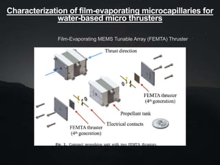
The document discusses water-based film-evaporation microthrusters.
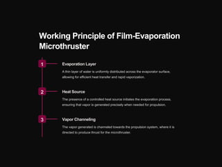
1. They utilize the film evaporation principle to expel water propellant through micro-nozzles using efficient thermal valving, allowing for precise maneuvering of small satellites with low power.
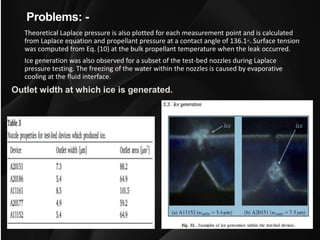
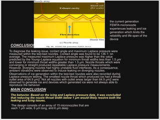
2. Testing showed maximum thrust occurs at nozzle throats less than 1.5 μm wide, but widths below 1 μm are needed to prevent leaking and ice generation issues.
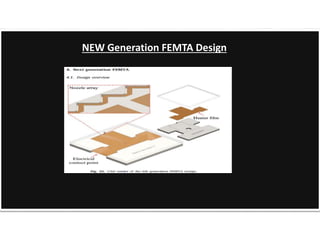
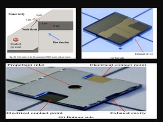
3. An improved design was proposed with an array of 1 μm wide nozzles that is expected to resolve prior reliability problems.
![Water-Based Microthrusters
or
Film-Evaporation Microthruster
Film-evaporation micro thrusters are a type of
propulsion system used in small satellites for precise
maneuvering in space. They utilize the film evaporation
principle to expel a propellant through a micro-nozzle,
allowing for efficient and controlled movement.
The use of water as a propellant offers environmental
and safety advantages, making it an attractive solution
for a wide range of emerging technologies.
by ROHAN SHARMA
[ Aeronautical ]](https://image.slidesharecdn.com/water-based-microthrusters-240222110436-256cf321/85/Water-Based-Micro-thrusters-for-nano-satellite-pptx-1-320.jpg)
![Water-Based Microthrusters
or
Film-Evaporation Microthruster
Film-evaporation micro thrusters are a type of
propulsion system used in small satellites for precise
maneuvering in space. They utilize the film evaporation
principle to expel a propellant through a micro-nozzle,
allowing for efficient and controlled movement.
The use of water as a propellant offers environmental
and safety advantages, making it an attractive solution
for a wide range of emerging technologies.
by ROHAN SHARMA
[ Aeronautical ]](https://image.slidesharecdn.com/water-based-microthrusters-240222110436-256cf321/75/Water-Based-Micro-thrusters-for-nano-satellite-pptx-1-2048.jpg)
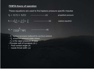
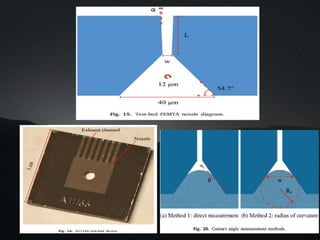
![FEMTA nozzle have shown that the flow is sonic at the exit of the throat. As a result, the
isentropic temperature and pressure at the nozzle throat exit are defined by Eqs. (4) and (5)
where 𝐶𝑝 is the specific heat and 𝑅 is the specific gas constant of water vapor.
DESIGN OF THRUSTER
𝑇𝑒=𝑇𝑖 1 −
𝑅
2𝐶𝑝−𝑅
-------------------------(4)
𝑃𝑒 = 𝑃𝑣 1 −
𝑅
2𝐶𝑝 − 𝑅
𝐶𝑝
𝑅
𝑢𝑒 = [2𝐶𝑝(𝑇𝑖 − 𝑇𝑒)]
1
2
𝑚 = 𝐴𝑒𝑢𝑒
𝑃𝑒
𝑅𝑇𝑒
𝐹 = 𝑚𝑢𝑒 + 𝑃𝑒𝐴𝑒
-------------------------(5)
-------------------------(6)
-------------------------(7)
-------------------------(8)](https://image.slidesharecdn.com/water-based-microthrusters-240222110436-256cf321/85/Water-Based-Micro-thrusters-for-nano-satellite-pptx-16-320.jpg)