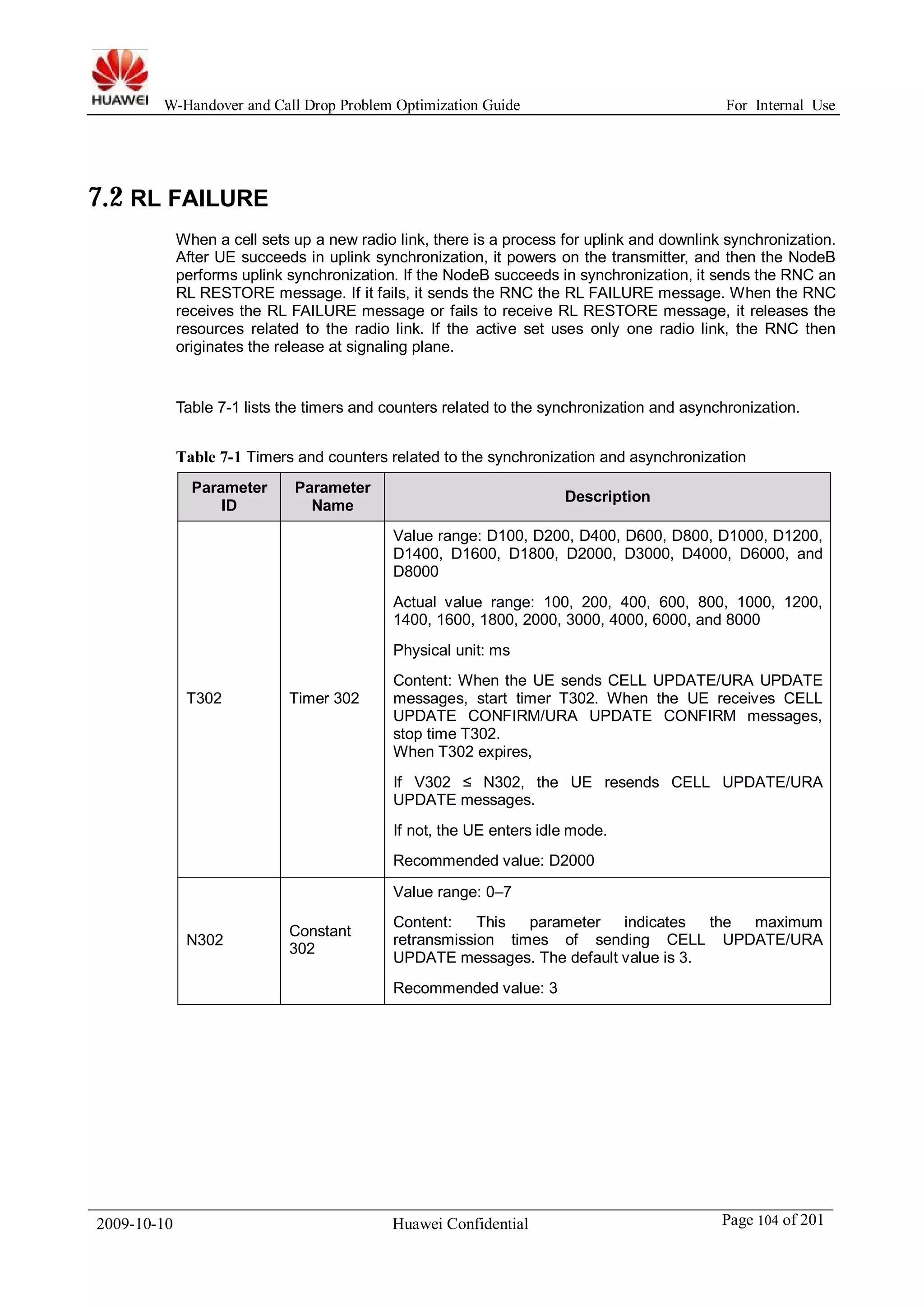
This document provides a guide for optimizing W-CDMA handover and call drop problems. It begins with an introduction and definitions of key performance indexes for handover and call drop. It then provides data analysis flows and optimization flows for different types of handovers including soft, hard, inter-RAT, HSDPA, and HSUPA handovers. It also includes analysis flows for optimizing call drop indexes using CDR and tracing data. The document concludes with frequently asked questions and analysis of common handover and call drop problems, along with appendices providing additional technical details.
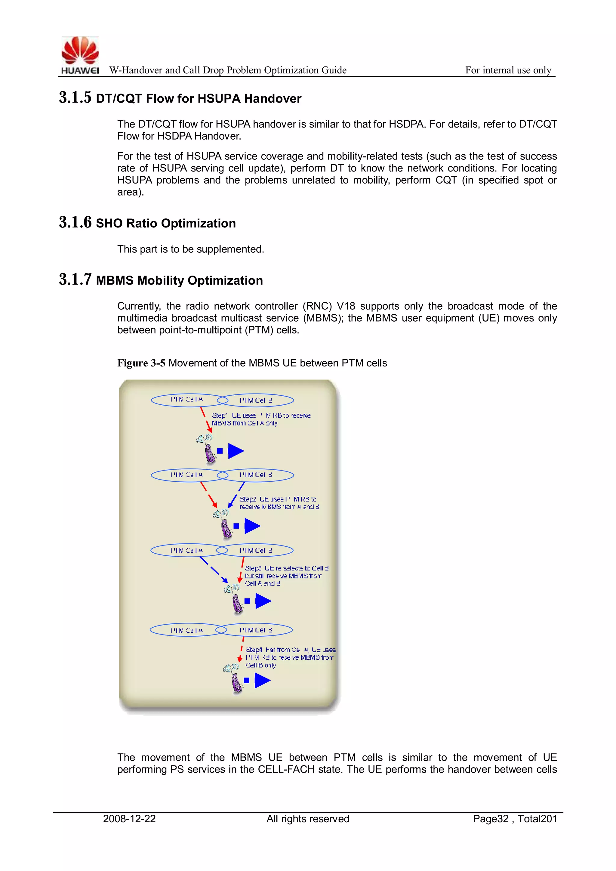
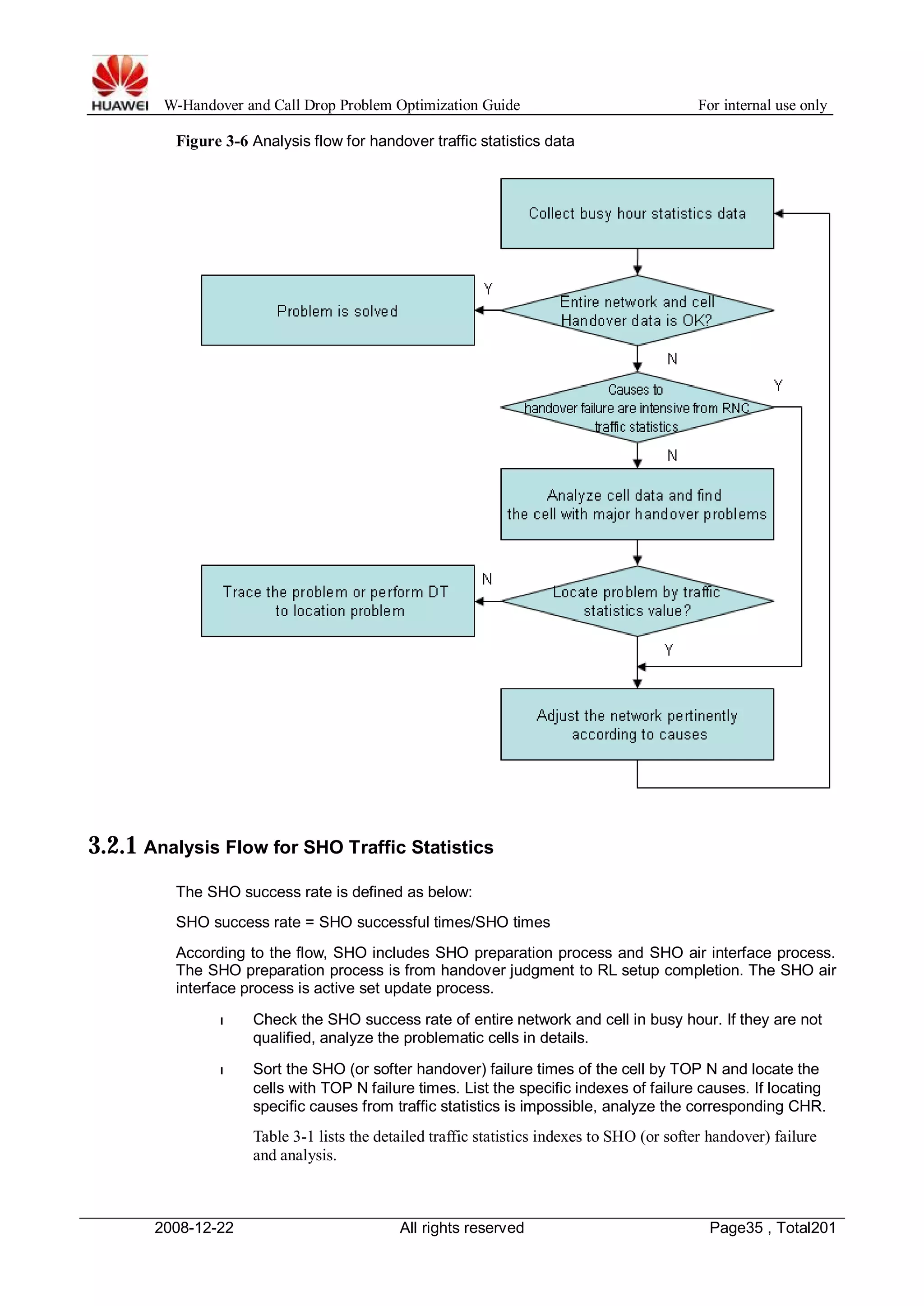
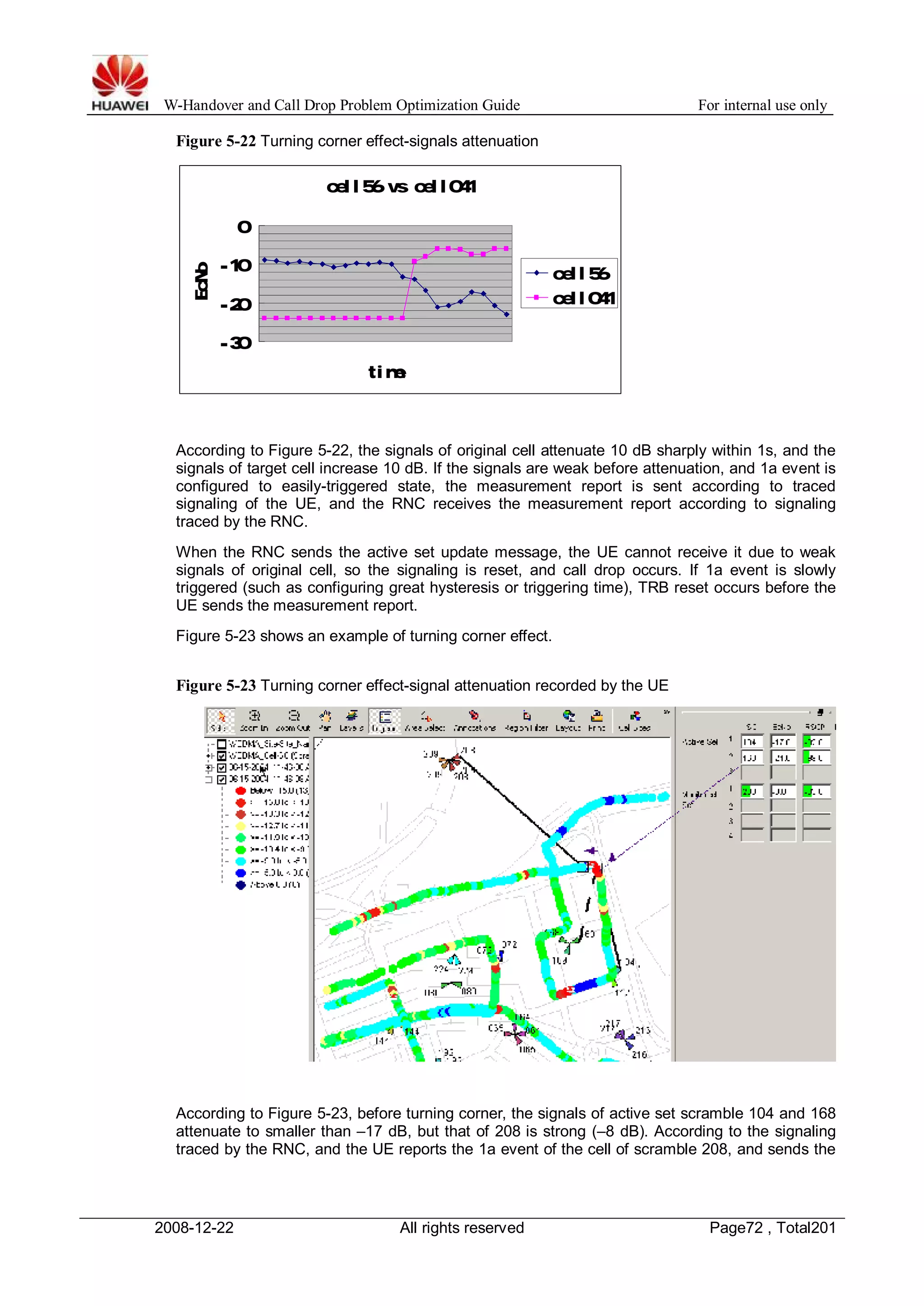
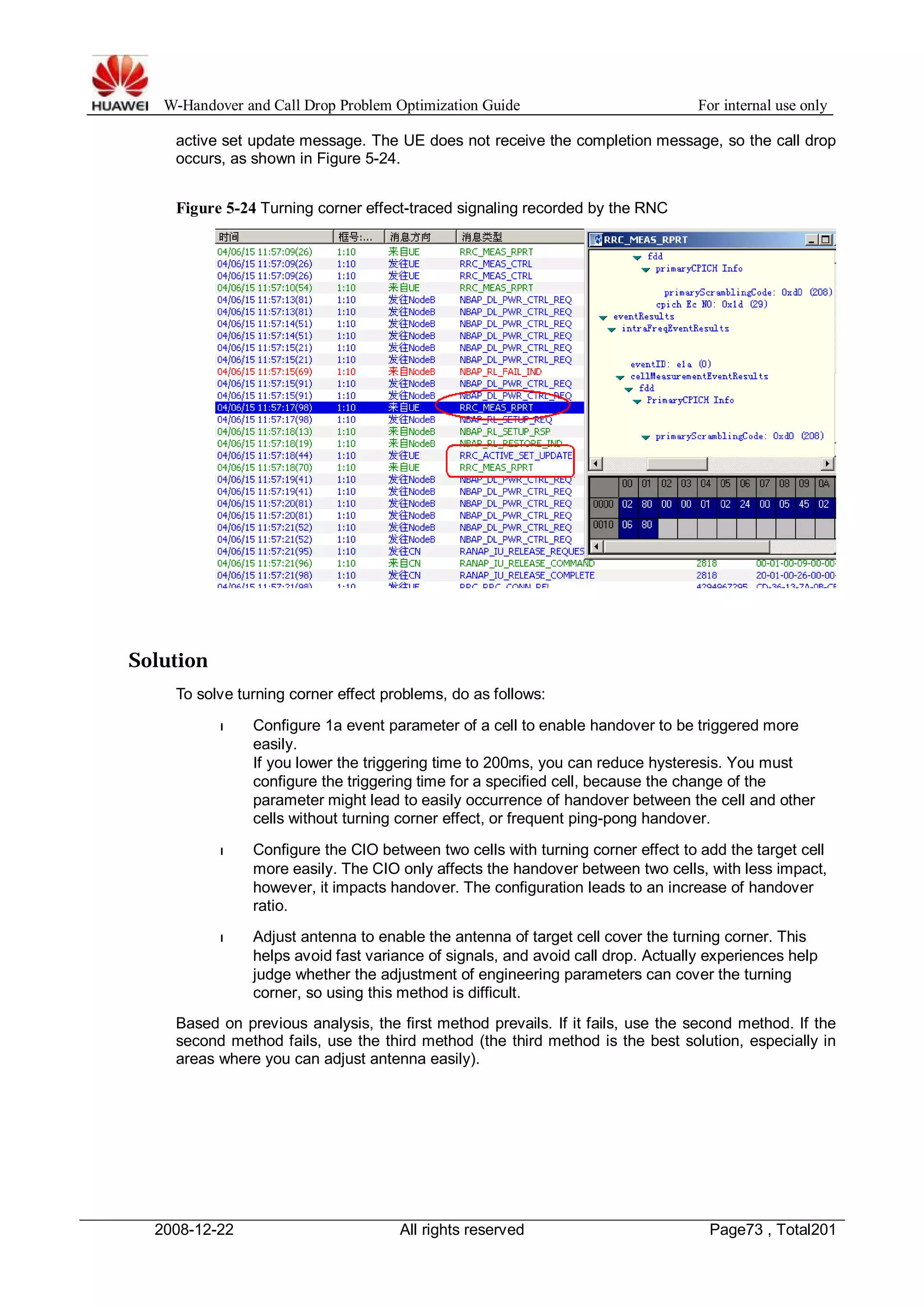
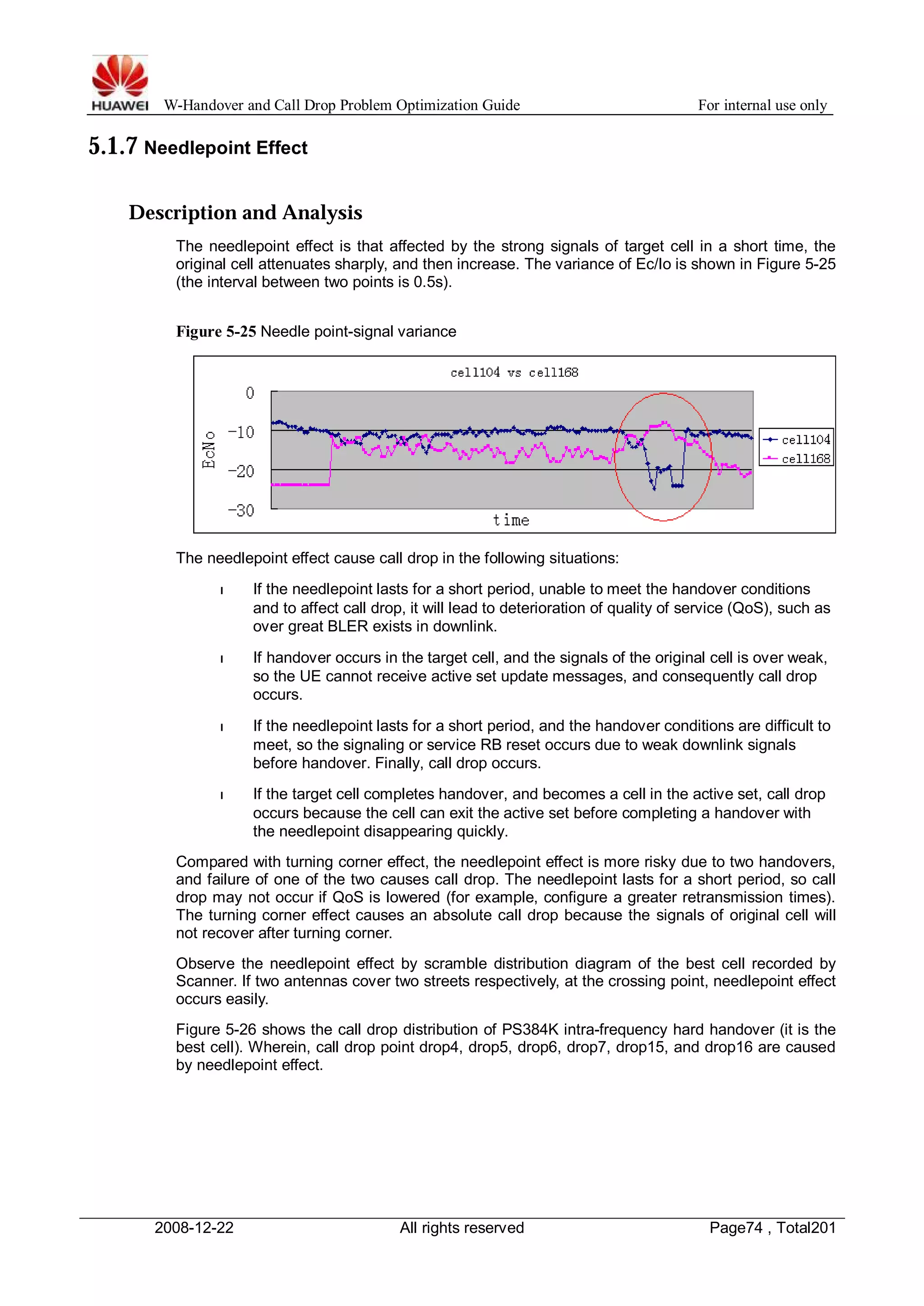
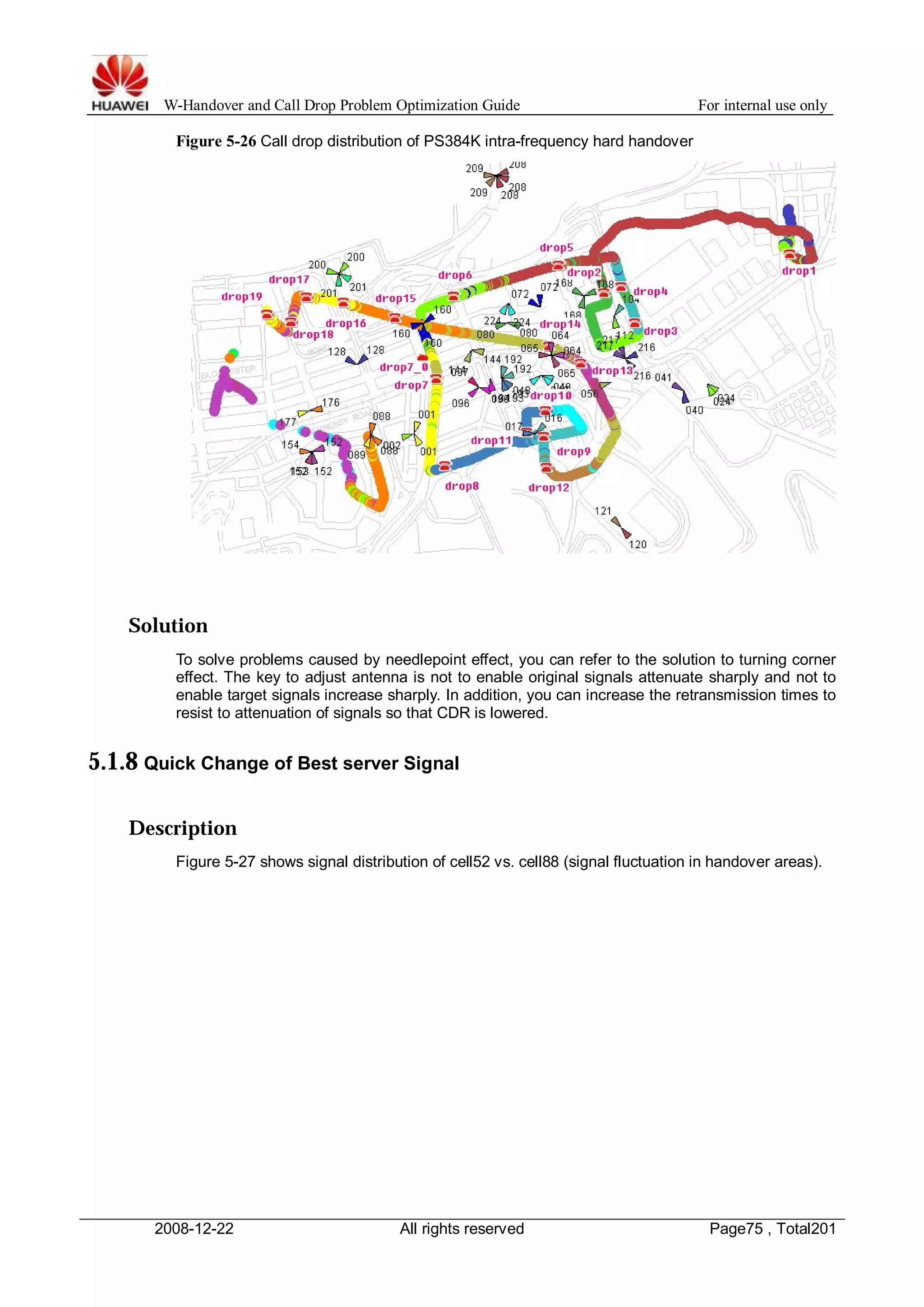
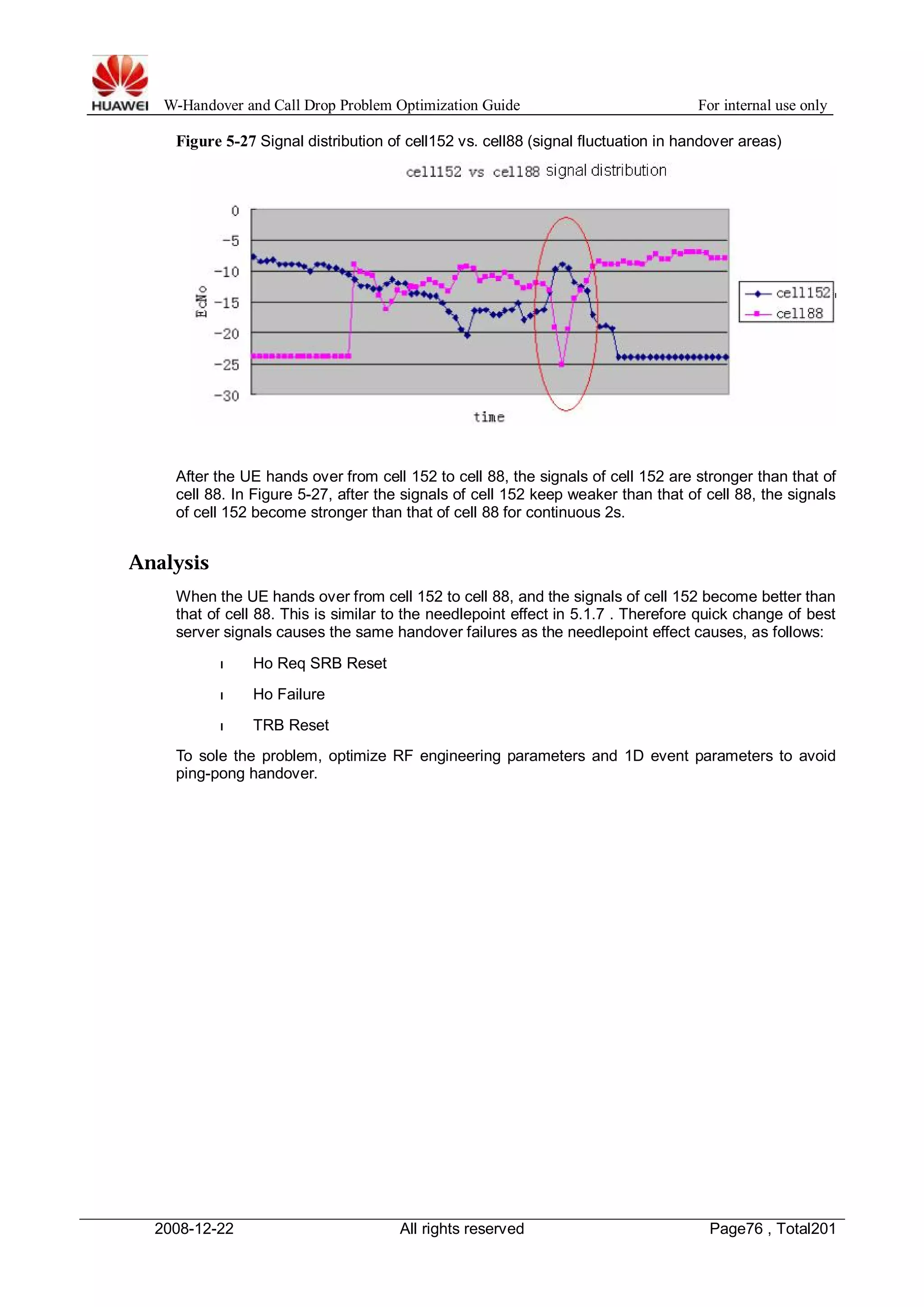
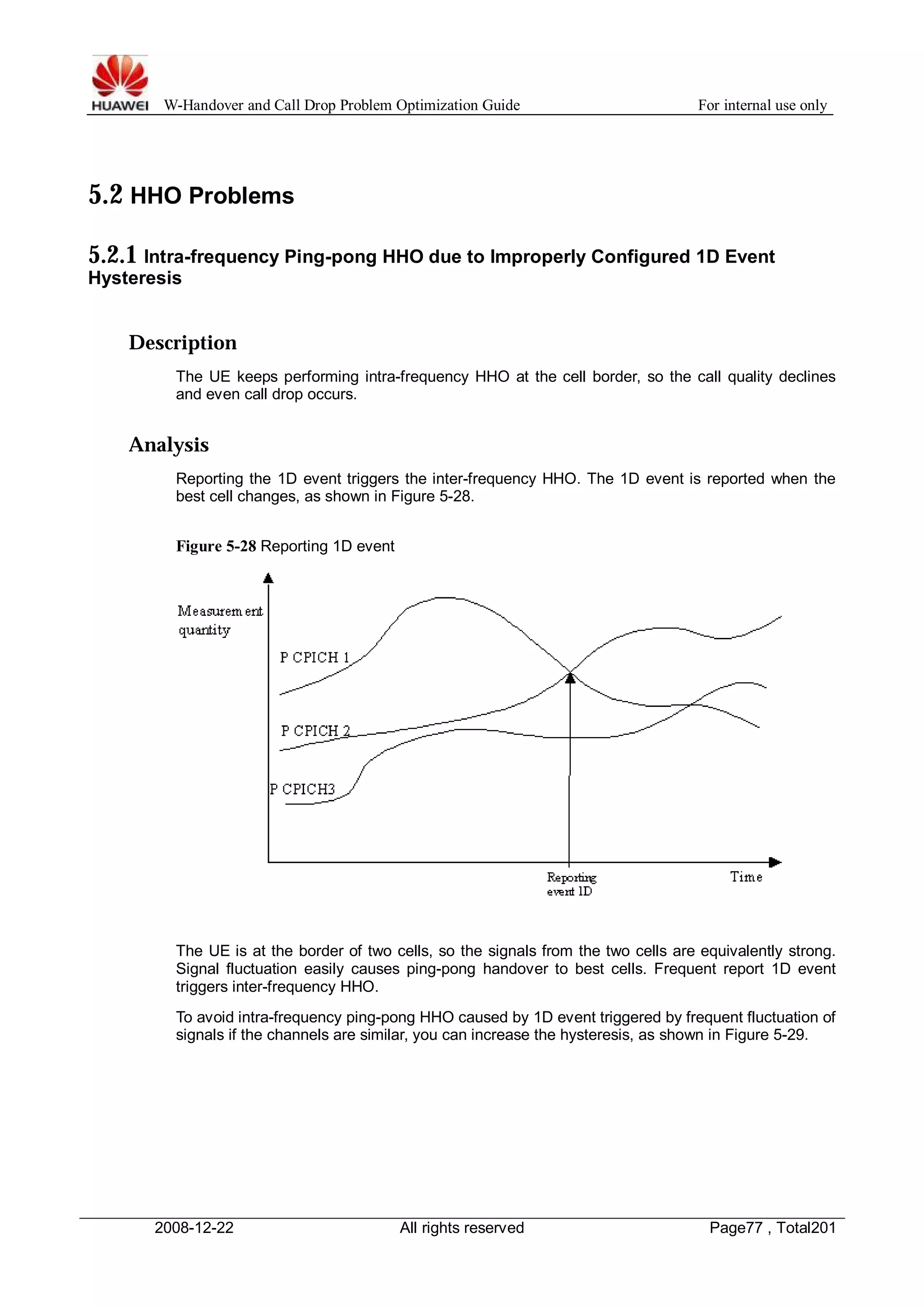
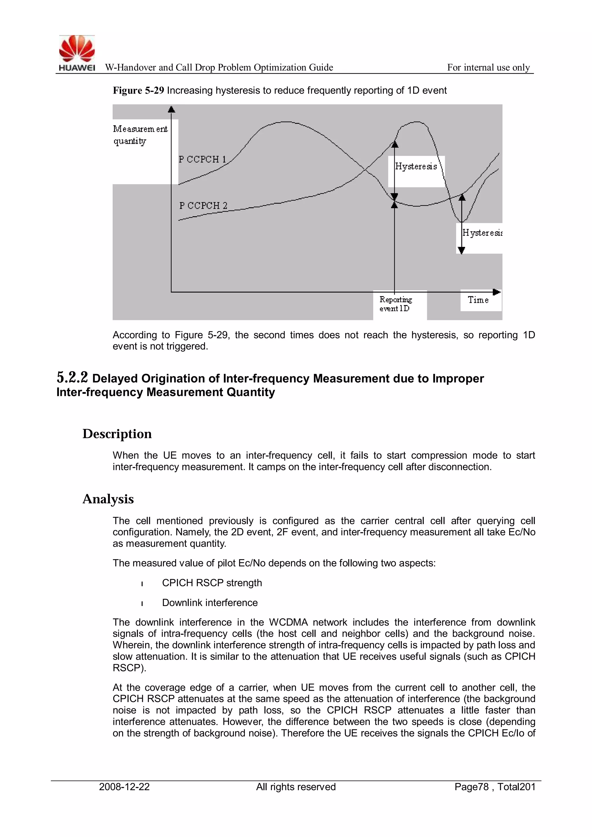
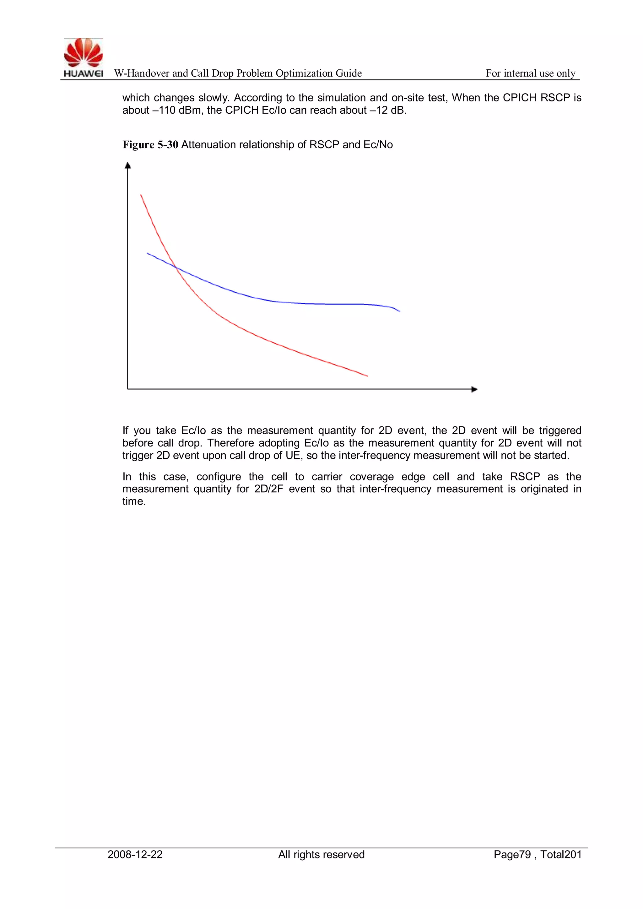
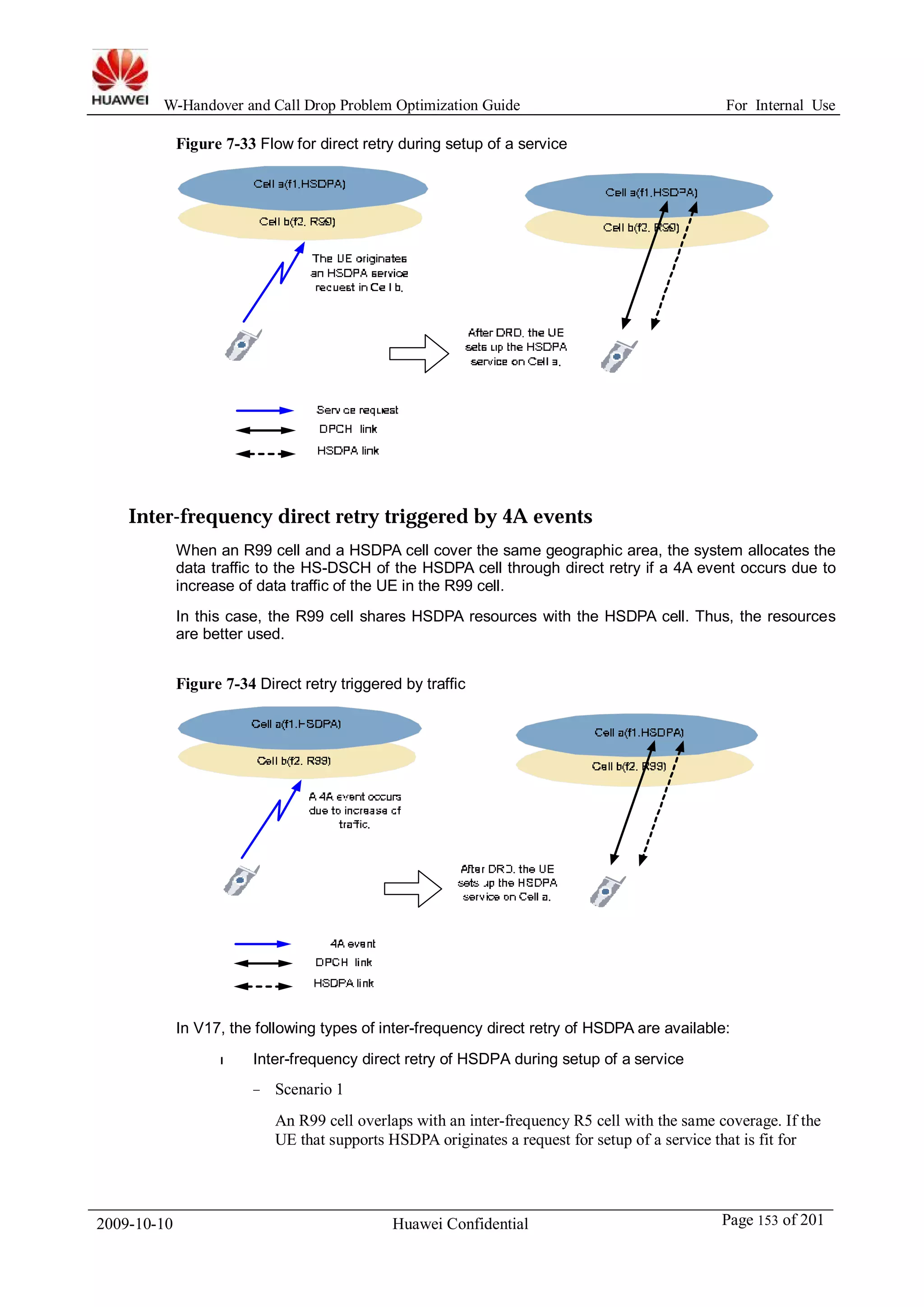
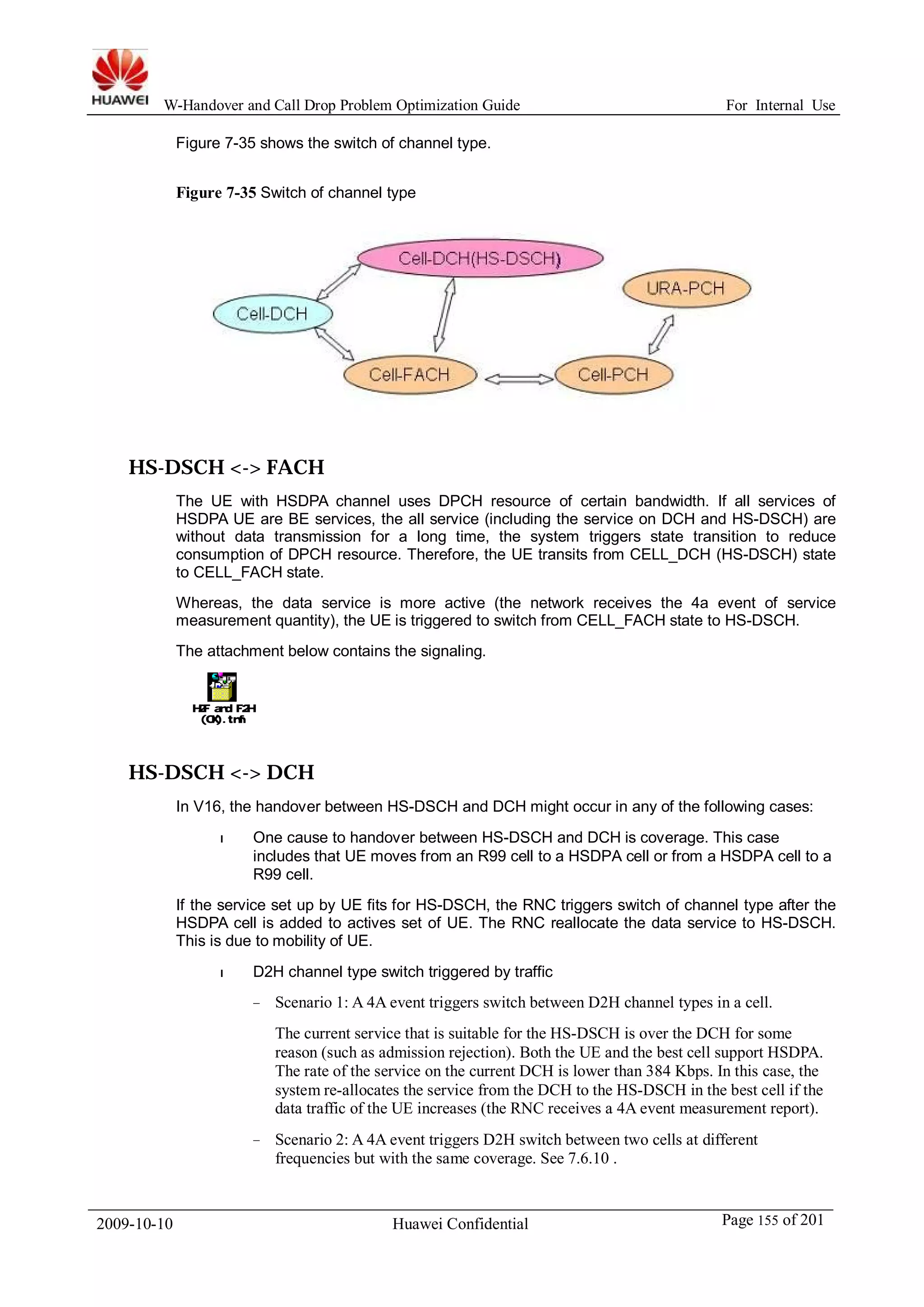
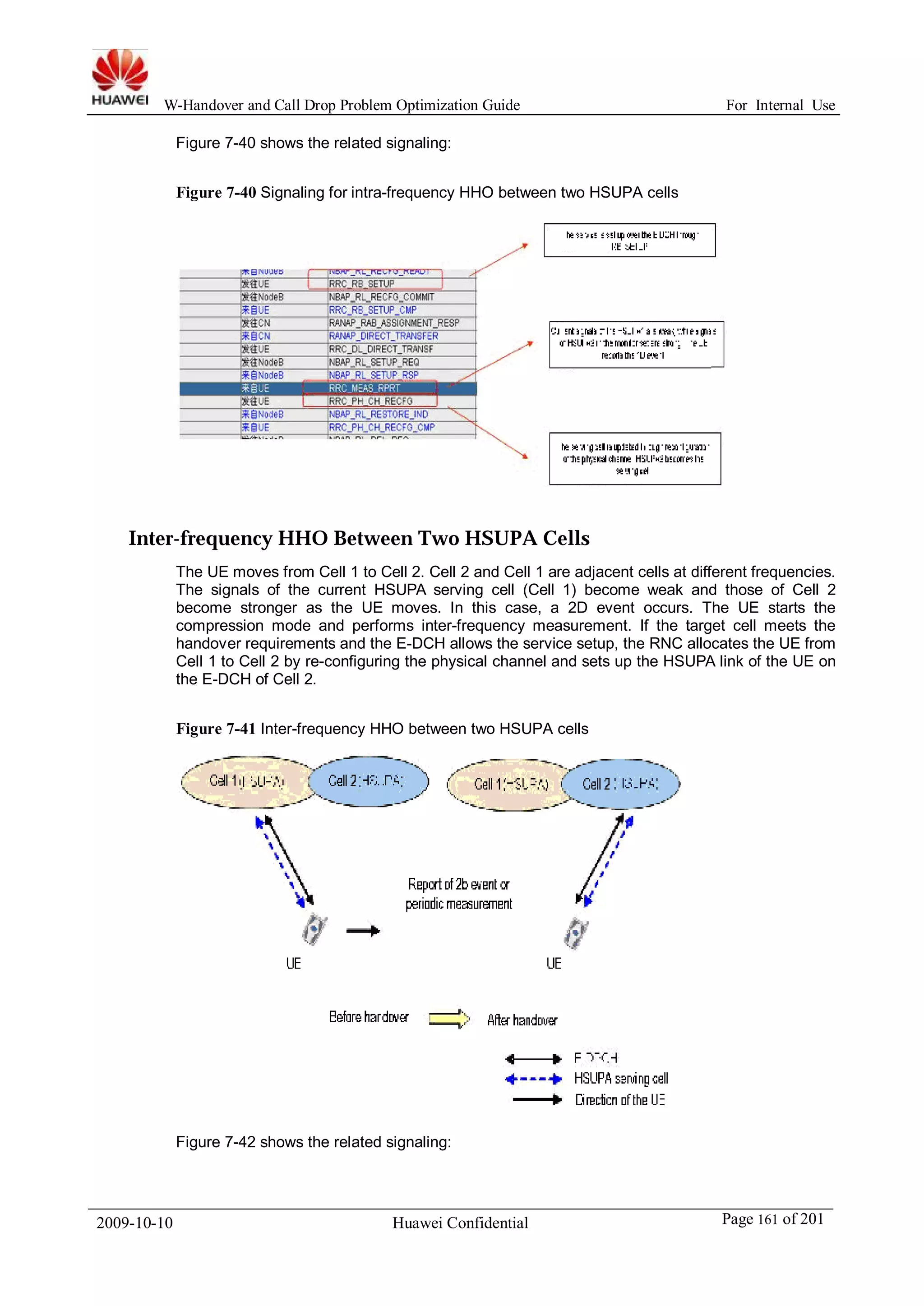
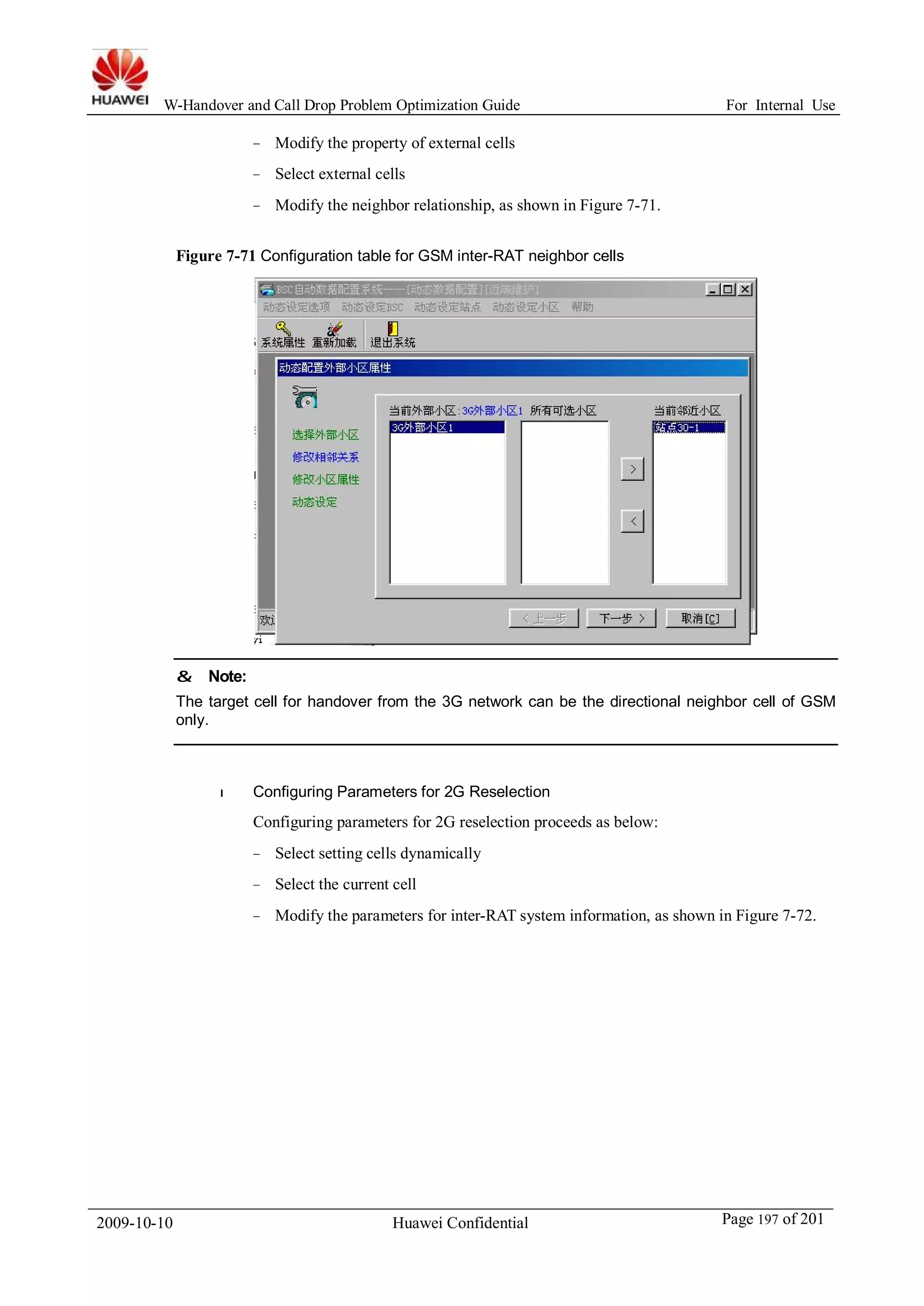
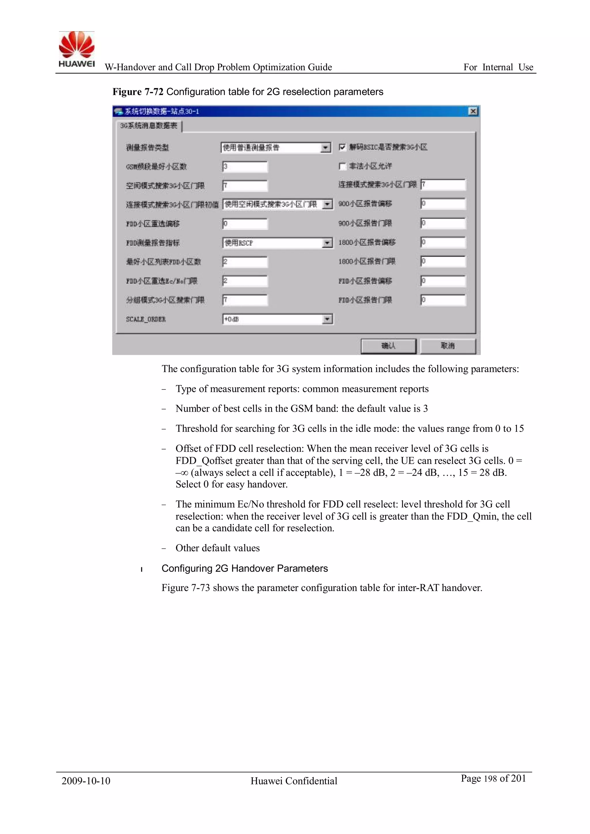
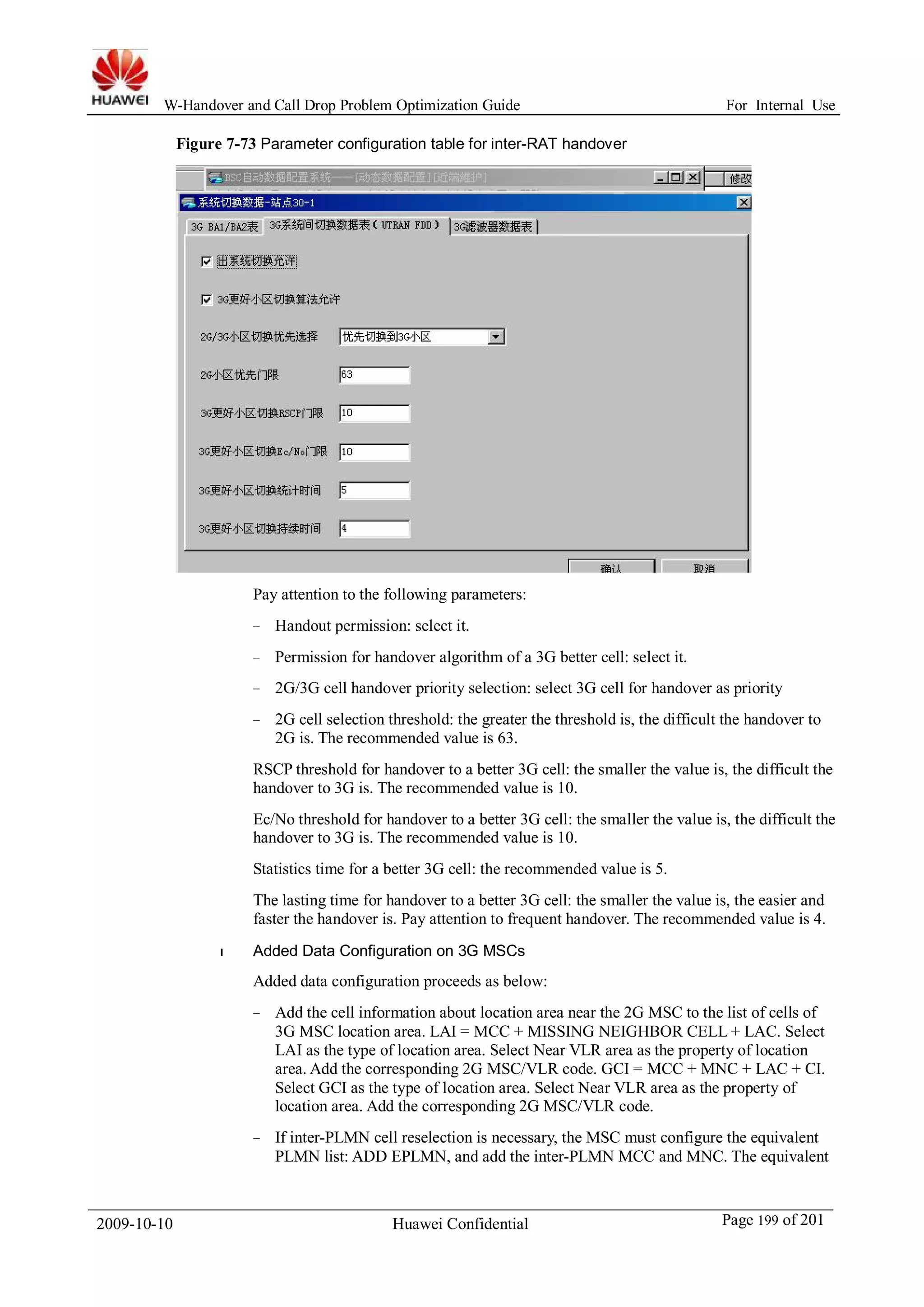
![W-Handover and Call Drop Problem Optimization Guide For Internal Use
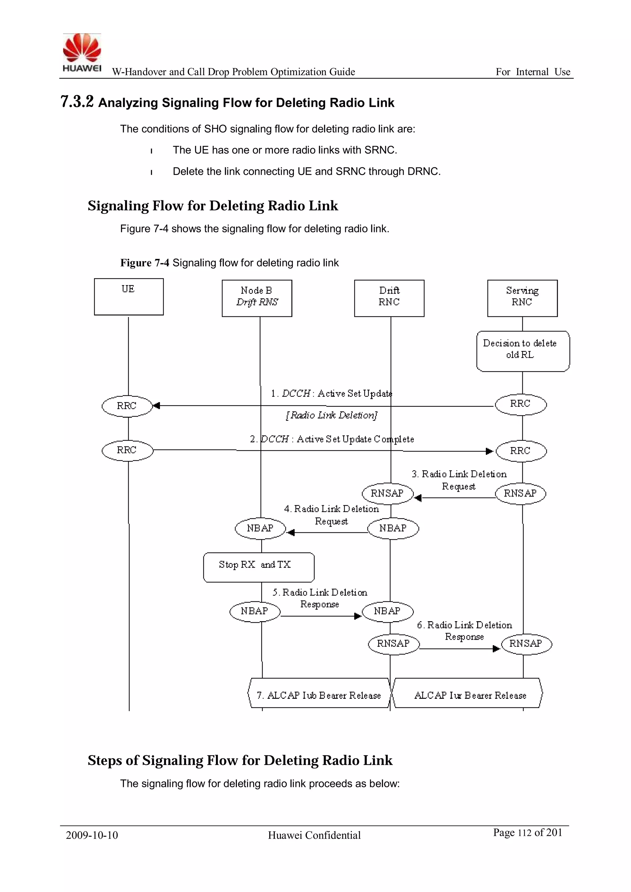
Figure 7-5 SHO signaling flow for adding and deleting radio link
Serving
RNC
Decision to setup
new RL and
release old RL
1. Radio Link Setup
Request
Drift
RNC
RNSAP RNSAP
4. Radio Link Setup
Response
UE Node B
Drift RNS
Node B
Serving RNS
NBAP 2. Radio Link Setup Request NBAP
Start RX
description
NBAP 3. Radio Link Setup Response NBAP
RNSAP RNSAP
5. ALCAP Iub Data Transport Bearer Setup ALCAP Iur Bearer Setup
6. Downlink Synchronisation
DCH-FP DCH-FP
7. Uplink Synchronisation
DCH-FP DCH-FP
Start TX
description
8. DCCH : Active Set Update Command
[Radio Link Addition & Deletion]
RRC RRC
9. DCCH : Active Set Update Complete
RRC RRC
NBAP 10. Radio Link Deletion Request
11. Radio Link Release Response
Stop RX and TX
NBAP
NBAP NBAP
12. ALCAP Iub Data Transport Bearer Release
Steps of SHO signaling Flow for Adding and Deleting Radio Link
The SHO signaling flow for adding and deleting radio link proceeds as below:
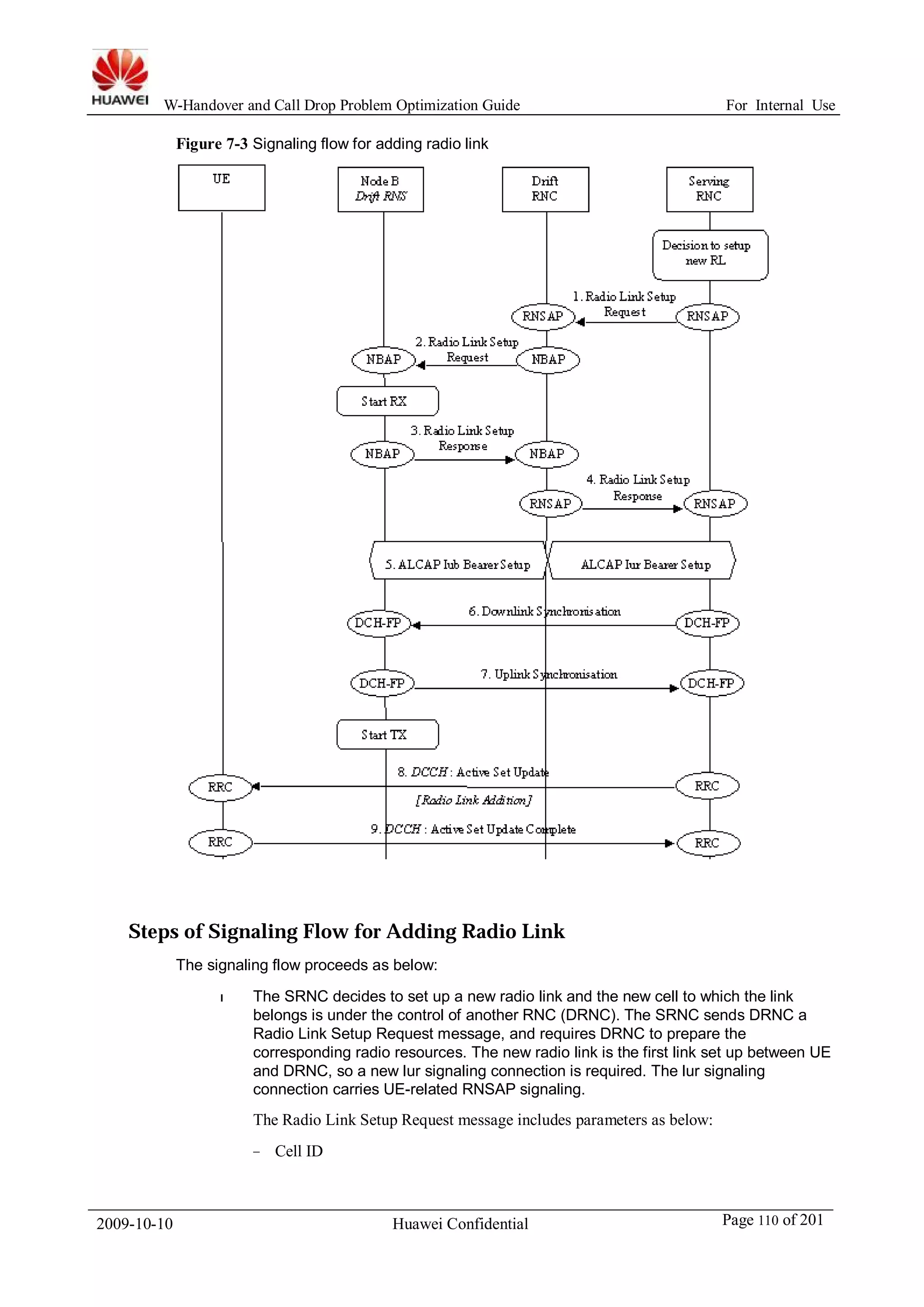
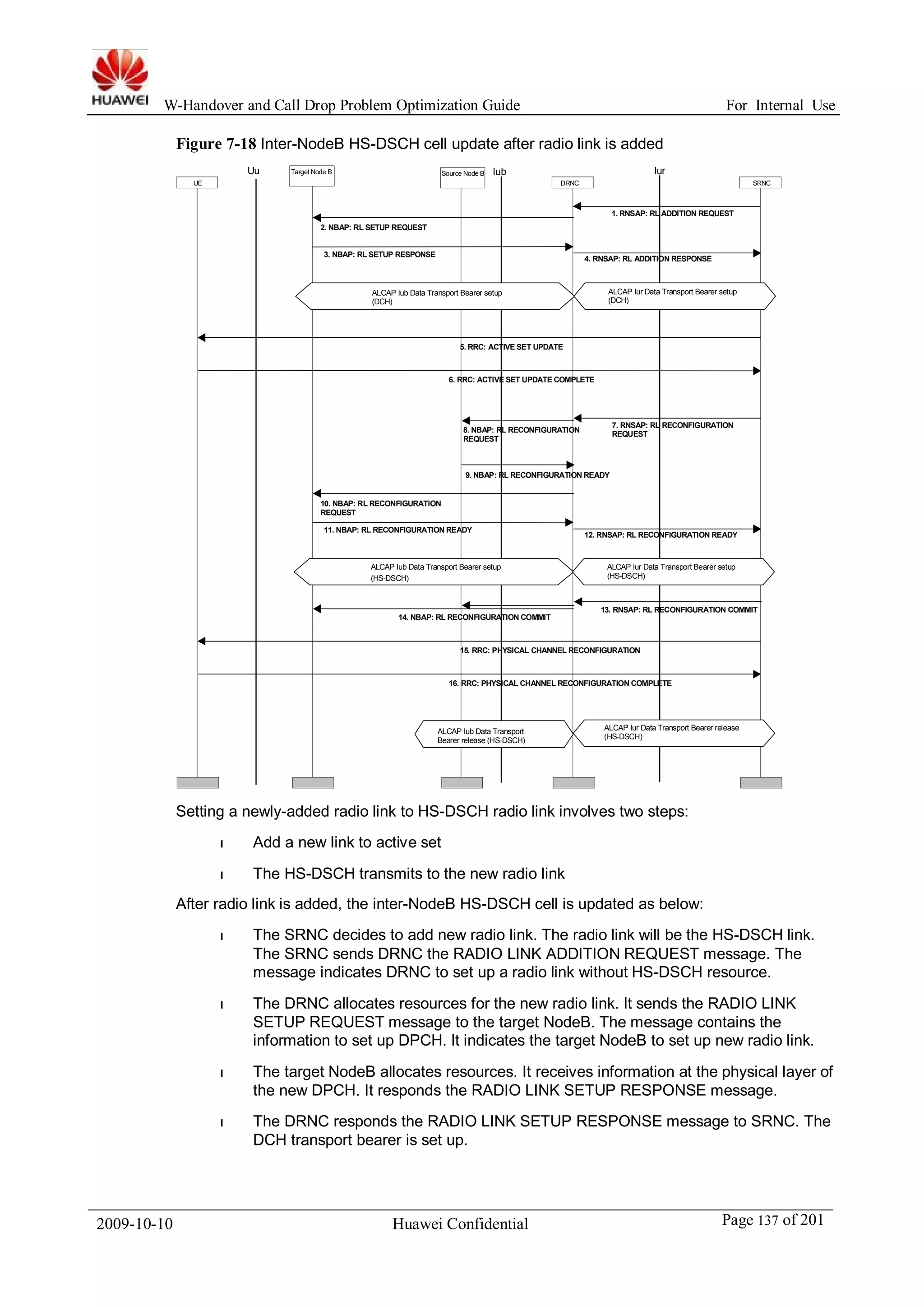
l The SRNC decides to set up a new radio link and the new cell to which the link
belongs is under the control of another RNC (DRNC). The SRNC sends DRNC a
Radio Link Setup Request message, and requires DRNC to prepare the
2009-10-10 Huawei Confidential Page 114 of 201](https://image.slidesharecdn.com/w-handover-and-call-drop-problem-optimization-guide-20081223-a-33-140916195416-phpapp01/75/W-handover-and-call-drop-problem-optimization-guide-20081223-a-3-3-114-2048.jpg)


![50 gsm bss network ps kpi (download rate) optimization manual[1].doc](https://cdn.slidesharecdn.com/ss_thumbnails/50gsmbssnetworkpskpidownloadrateoptimizationmanual1-140618023140-phpapp01-thumbnail.jpg?width=640&height=640&fit=bounds)
![13 gsm bss network kpi (network interference) optimization manual[1].doc](https://cdn.slidesharecdn.com/ss_thumbnails/13gsmbssnetworkkpinetworkinterferenceoptimizationmanual1-140618022430-phpapp01-thumbnail.jpg?width=640&height=640&fit=bounds)

![10 gsm bss network kpi (uplink downlink balance) optimization manual[1].doc](https://cdn.slidesharecdn.com/ss_thumbnails/10gsmbssnetworkkpiuplink-downlinkbalanceoptimizationmanual1-140618022209-phpapp01-thumbnail.jpg?width=640&height=640&fit=bounds)