SYLLABUS – MODULE2
•Introduction and Transport-Layer Services: Relationship Between Transport
and Network Layers, Overview of the Transport Layer in the Internet.
•Multiplexing and Demultiplexing:
•Connectionless Transport - UDP: UDP Segment Structure, UDP Checksum.
•Principles of Reliable Data Transfer: Building a Reliable Data Transfer Protocol,
Pipelined Reliable Data Transfer Protocols, Go-Back-N, Selective repeat.
•Connection-Oriented Transport TCP: The TCP Connection, TCP Segment
Structure, Round- Trip Time Estimation and Timeout, Reliable Data Transfer,
Flow Control, TCP Connection Management.
•Principles of Congestion Control: The Causes and the Costs of Congestion,
Approaches to Congestion Control, Network-assisted congestion-control
example, ATM ABR Congestion control.
•TCP Congestion Control: Fairness.
3.
3.1 Introduction andTransport-Layer Services
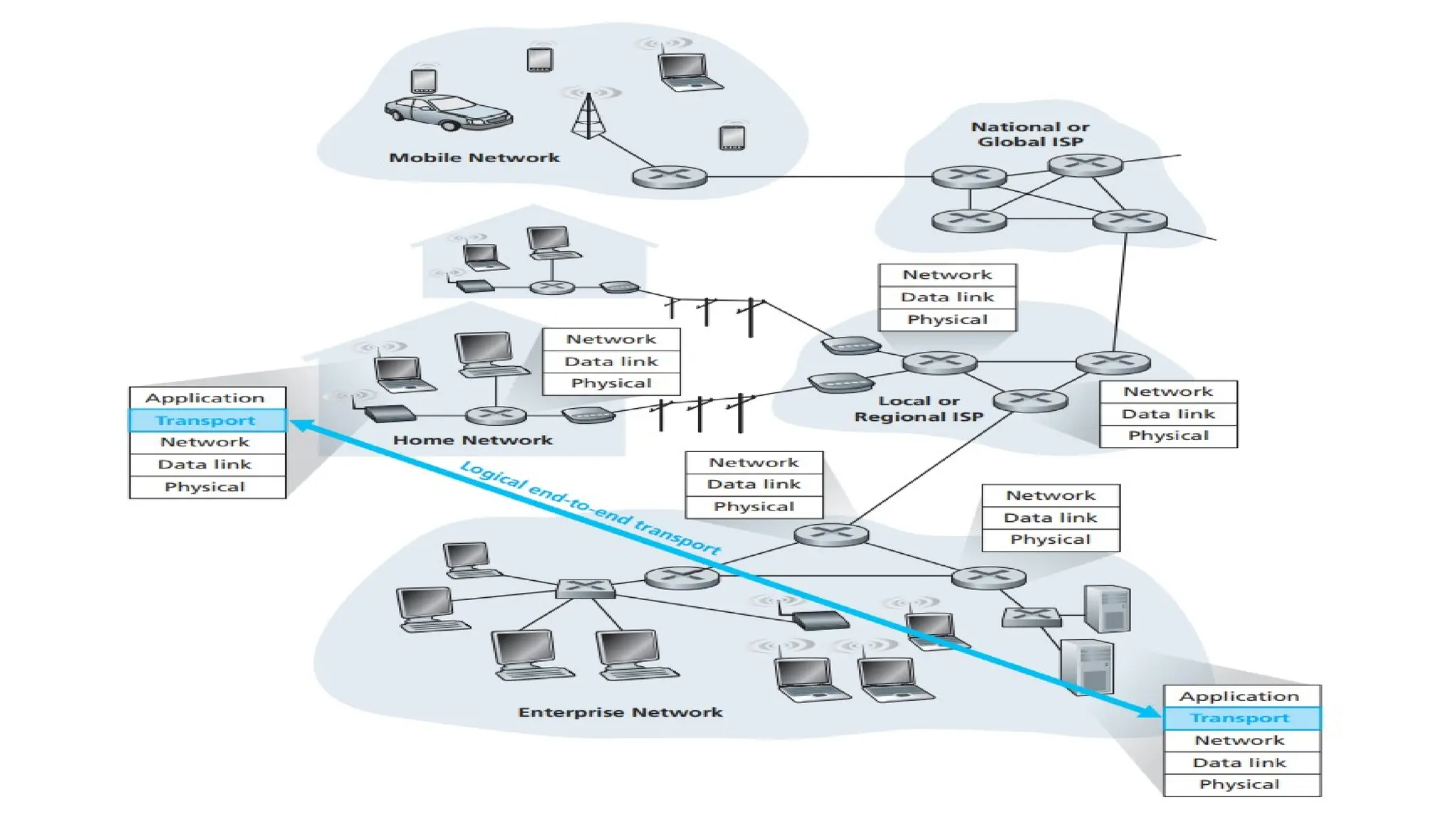
•Relationship Between Transport and Network Layers.
• Overview of the Transport Layer in the Internet.
4.
Transport-Layer Services
•A transport-layerprotocol provides for
logical communication between application
processes running on different hosts.
•Application processes use the logical
communication provided by the transport
layer to send messages to each other.
6.
•Transport-layer protocols areimplemented in the
end systems but not in network routers.
•On the sending side, the transport layer converts
the application-layer messages it receives from a
sending application process into transport-layer
packets, known as transport-layer segments.
7.
Transport Segment
•The Segmentis done by (possibly) breaking the
application messages into smaller chunks and adding a
transport-layer header to each chunk to create the
transport-layer segment. The transport layer then
passes the segment to the network layer at the
sending end system, where the segment is
encapsulated within a network-layer packet (a
datagram) and sent to the destination.
8.
•Network routers actonly on the network-layer fields
of the datagram; that is, they do not examine the
fields of the transport-layer segment encapsulated
with the datagram.
•On the receiving side, the network layer extracts the
transport-layer segment from the datagram and
passes the segment up to the transport layer. The
transport layer then processes the received segment,
making the data in the segment available to the
receiving application.
9.
3.1.1 Relationship Between
Transportand Network Layers
•A transport-layer protocol provides logical
communication between processes running on
different hosts, a network-layer protocol provides
logical communication between hosts.
10.
3.1.1 Relationship BetweenTransport and
Network Layers
•Transport-layer protocols live in the end systems.
Within an end system, a transport protocol moves
messages from application processes to the
network edge (that is, the network layer) and vice
versa, but it doesn’t have any say about how the
messages are moved within the network core.
11.
3.1.1 Relationship BetweenTransport and
Network Layers -- Contd…
•Multiple transport protocols are available, with
each protocol offering a different service model
to applications.
12.
3.1.1 Relationship BetweenTransport and
Network Layers -- Contd…
•Services that a transport protocol can provide are
constrained by the service model of the underlying
network-layer protocol. If the network-layer protocol
cannot provide delay or bandwidth guarantees for
transport layer segments sent between hosts, then
the transport-layer protocol cannot provide delay or
bandwidth guarantees for application messages sent
between processes.
13.
3.1.1 Relationship BetweenTransport and
Network Layers -- Contd…
•Some services can be offered by a transport
protocol even when the underlying network
protocol doesn’t offer the corresponding service
at the network layer.
14.
3.1.1 Relationship BetweenTransport and
Network Layers -- Contd…
•For example, a transport protocol can
offer reliable data transfer service to an
application even when the underlying
network protocol is unreliable, that is,
even when the network protocol loses,
garbles, or duplicates packets.
15.
3.1.1 Relationship BetweenTransport and
Network Layers -- Contd…
•As another example, a transport protocol
can use encryption to guarantee that
application messages are not read by
intruders, even when the network layer
cannot guarantee the confidentiality of
transport-layer segments.
16.
3.1.2 Overview ofthe Transport Layer
in the Internet
•A TCP/IP network, makes two distinct transport-
layer protocols available to the application layer.
•UDP provides an unreliable, connectionless
service to the invoking application.
•TCP provides a reliable, connection-oriented
service to the invoking application.
17.
Internet’s network-layer protocol IP
IP Internet Protocol
•IP provides logical communication between hosts.
•The IP service model is a best-effort delivery service.
This means that IP makes its “best effort” to deliver
segments between communicating hosts, but it makes
no guarantees.
•It does not guarantee segment delivery, it does not
guarantee orderly delivery of segments, and it does not
guarantee the integrity of the data in the segments. For
these reasons, IP is said to be an unreliable service.
18.
3.2 Multiplexing andDemultiplexing
•Extending the host-to-host delivery service
provided by the network layer to a process-to-
process delivery service for applications
running on the hosts.
19.
•At the destinationhost, the transport layer receives
segments from the network layer just below.
•The transport layer has the responsibility of
delivering the data in these segments to the
appropriate application process running in the host.
20.
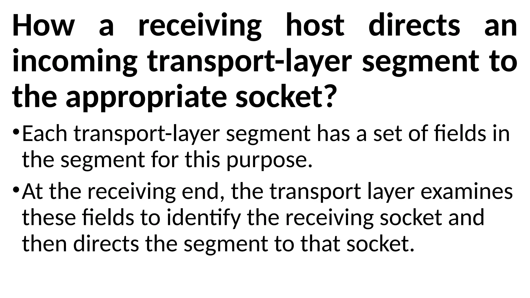
How a receivinghost directs an
incoming transport-layer segment to
the appropriate socket?
•Each transport-layer segment has a set of fields in
the segment for this purpose.
•At the receiving end, the transport layer examines
these fields to identify the receiving socket and
then directs the segment to that socket.
21.
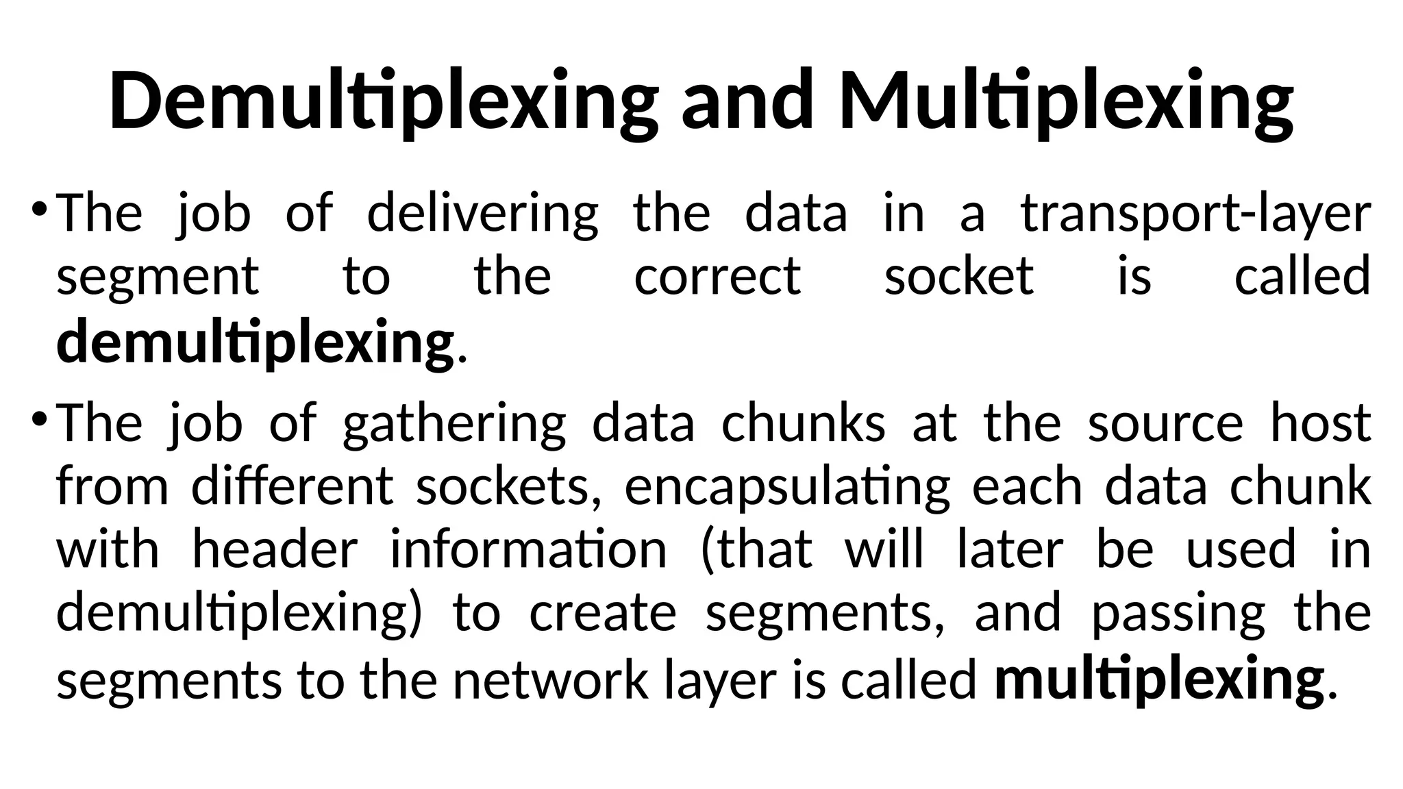
Demultiplexing and Multiplexing
•Thejob of delivering the data in a transport-layer
segment to the correct socket is called
demultiplexing.
•The job of gathering data chunks at the source host
from different sockets, encapsulating each data chunk
with header information (that will later be used in
demultiplexing) to create segments, and passing the
segments to the network layer is called multiplexing.
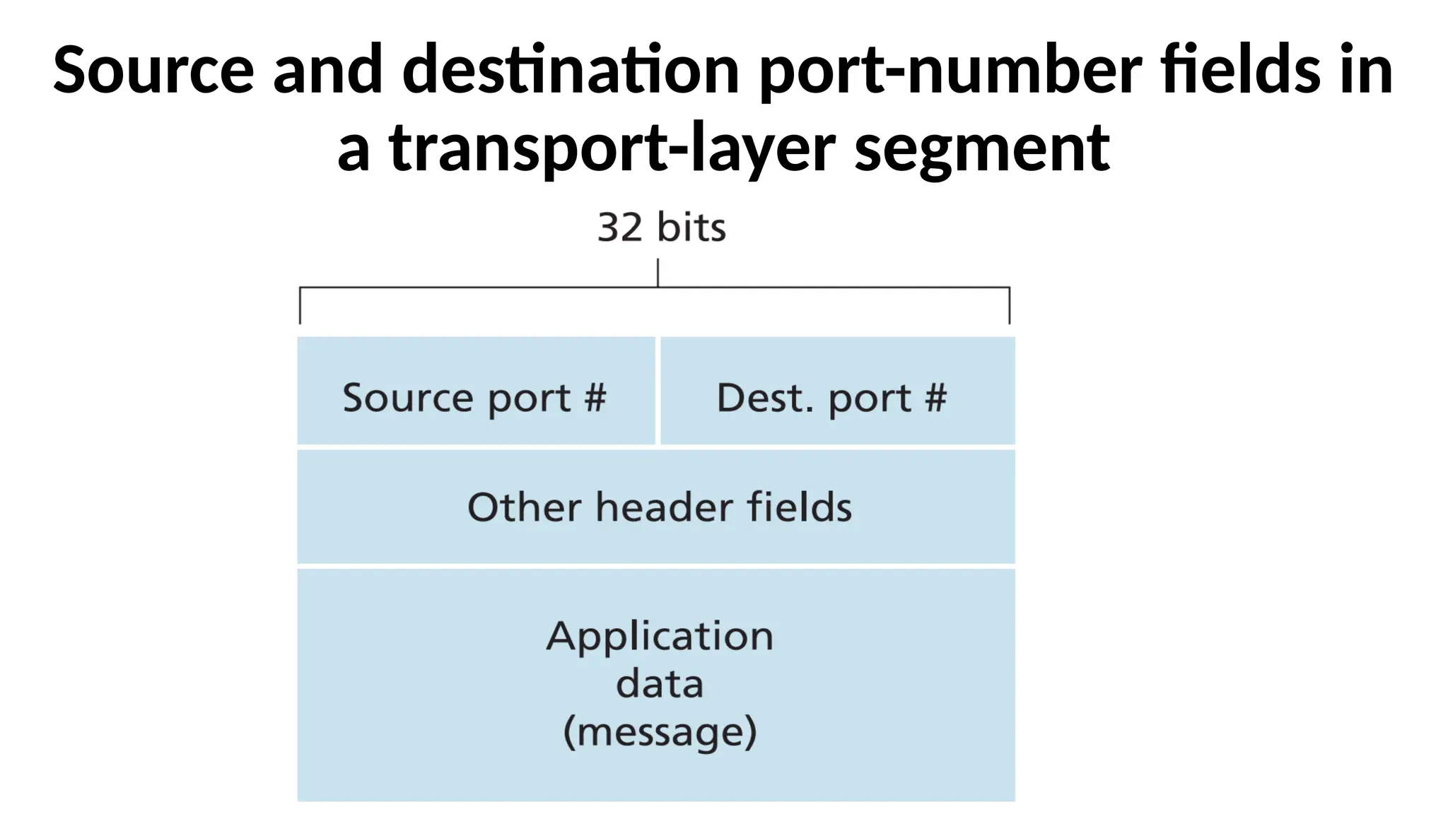
Transport-layer multiplexing requires
•thatsockets have unique identifiers, and
•that each segment have special fields that
indicate the socket to which the segment is
to be delivered. These special fields are the
source port number field and the
destination port number field.
25.
•Each port numberis a 16-bit number, ranging from 0
to 65535.
•The port numbers ranging from 0 to 1023 are called
well-known port numbers and are restricted, which
means that they are reserved for use by well-known
application protocols such as HTTP (which uses port
number 80) and FTP (which uses port number 21).
•The list of well-known port numbers is given in RFC
1700 and is updated at http://www.iana.org
26.
How the transportlayer could implement the
demultiplexing service
•Each socket in the host could be assigned a port number.
•When a segment arrives at the host, the transport layer
examines the destination port number in the segment.
•It directs the segment to the corresponding socket.
•The segment’s data then passes through the socket into
the attached process.
27.
Connectionless Multiplexing andDemultiplexing
•The Python program running in a host can create a
UDP socket with the line:
clientSocket = socket(socket.AF_INET,
socket.SOCK_DGRAM)
•When a UDP socket is created, the transport layer
automatically assigns a port number to the socket.
•The transport layer assigns a port number in the
range 1024 to 65535 that is currently not being
used by any other UDP port in the host.
28.
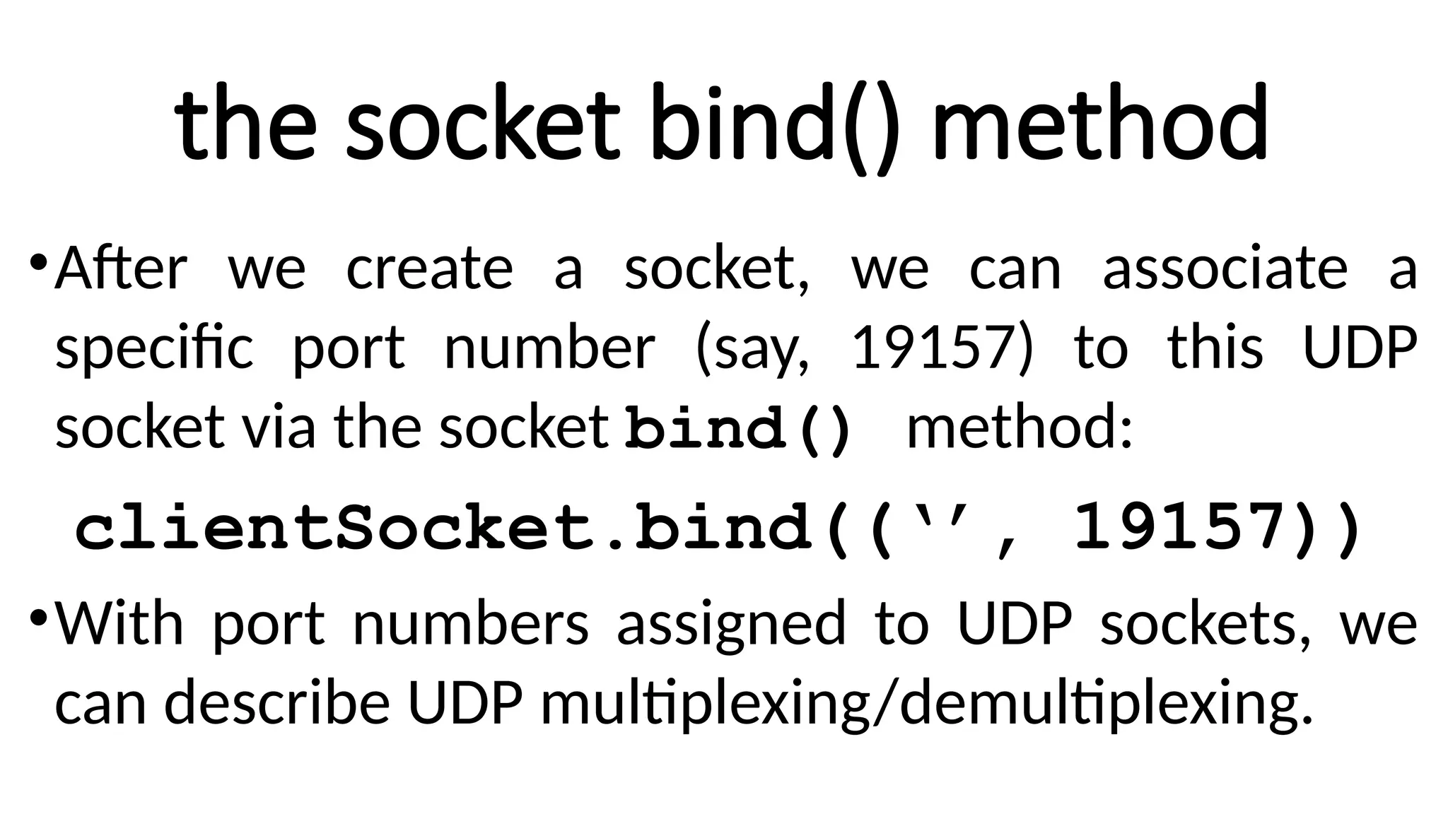
the socket bind()method
•After we create a socket, we can associate a
specific port number (say, 19157) to this UDP
socket via the socket bind() method:
clientSocket.bind((‘’, 19157))
•With port numbers assigned to UDP sockets, we
can describe UDP multiplexing/demultiplexing.
29.
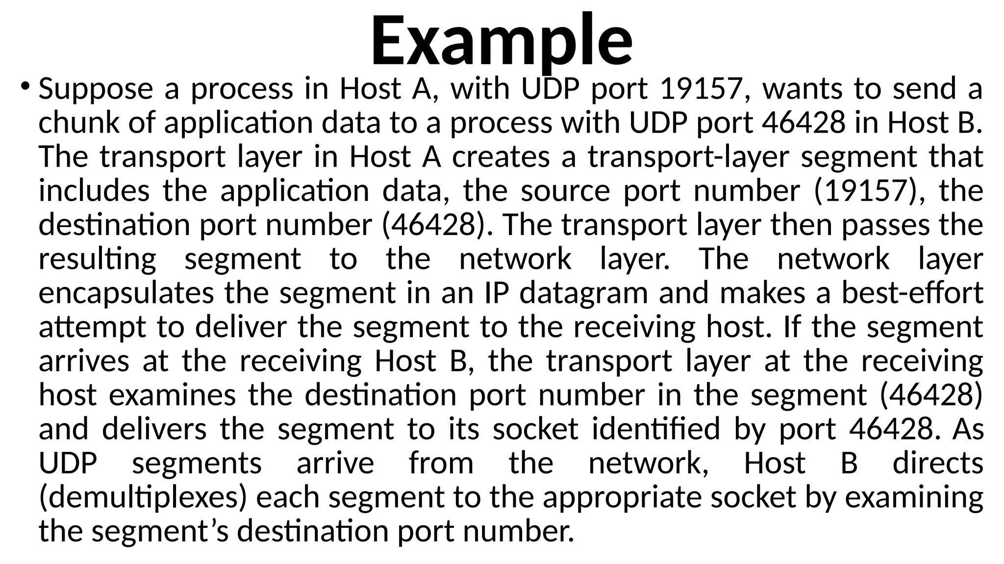
Example
• Suppose aprocess in Host A, with UDP port 19157, wants to send a
chunk of application data to a process with UDP port 46428 in Host B.
The transport layer in Host A creates a transport-layer segment that
includes the application data, the source port number (19157), the
destination port number (46428). The transport layer then passes the
resulting segment to the network layer. The network layer
encapsulates the segment in an IP datagram and makes a best-effort
attempt to deliver the segment to the receiving host. If the segment
arrives at the receiving Host B, the transport layer at the receiving
host examines the destination port number in the segment (46428)
and delivers the segment to its socket identified by port 46428. As
UDP segments arrive from the network, Host B directs
(demultiplexes) each segment to the appropriate socket by examining
the segment’s destination port number.
30.
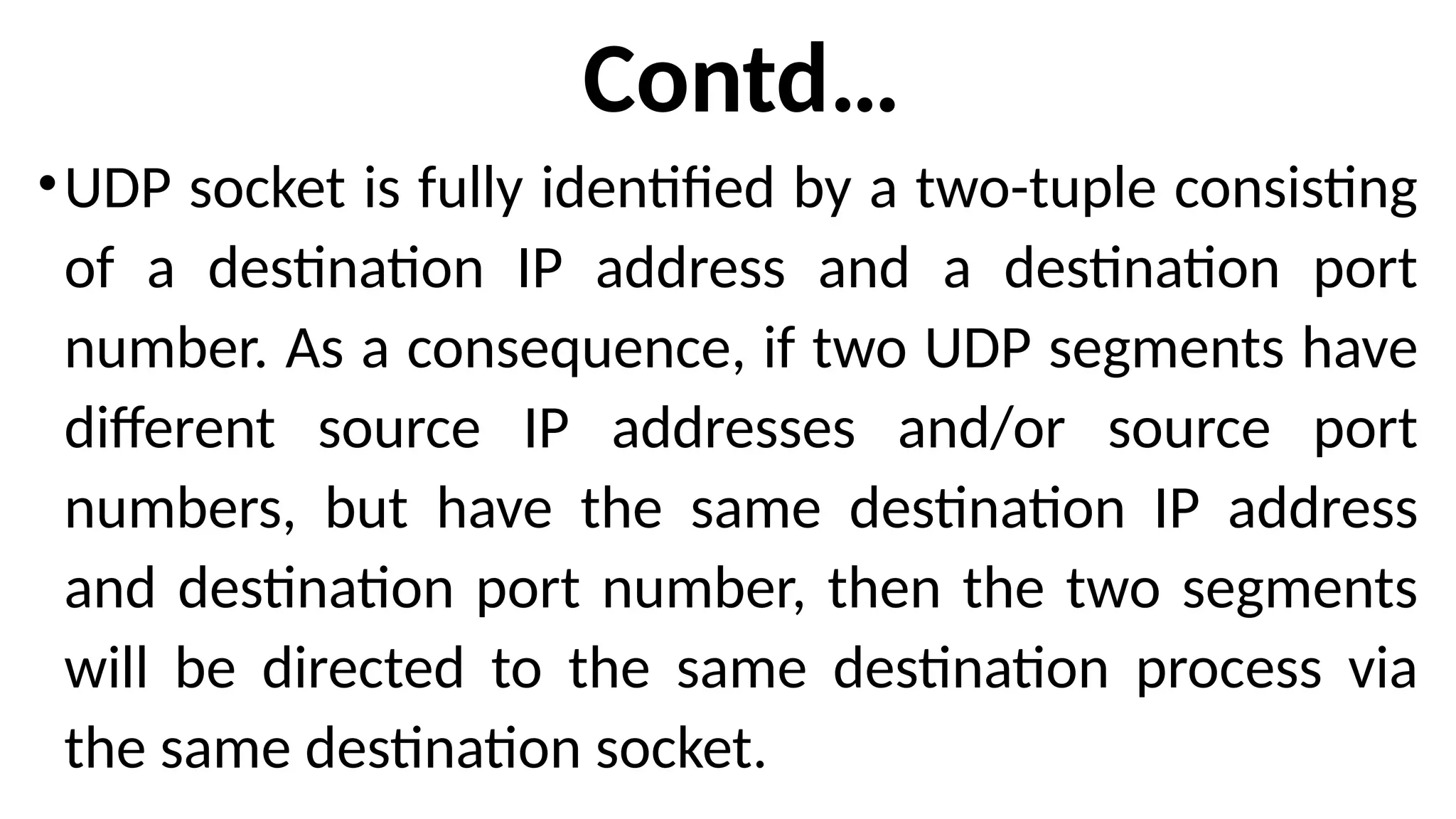
Contd…
•UDP socket isfully identified by a two-tuple consisting
of a destination IP address and a destination port
number. As a consequence, if two UDP segments have
different source IP addresses and/or source port
numbers, but have the same destination IP address
and destination port number, then the two segments
will be directed to the same destination process via
the same destination socket.
31.
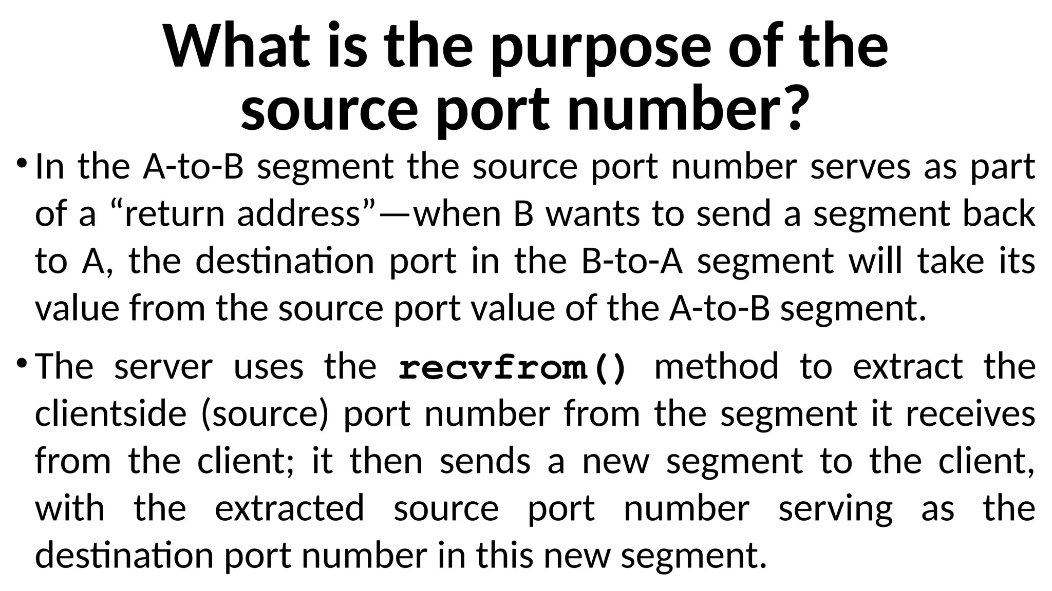
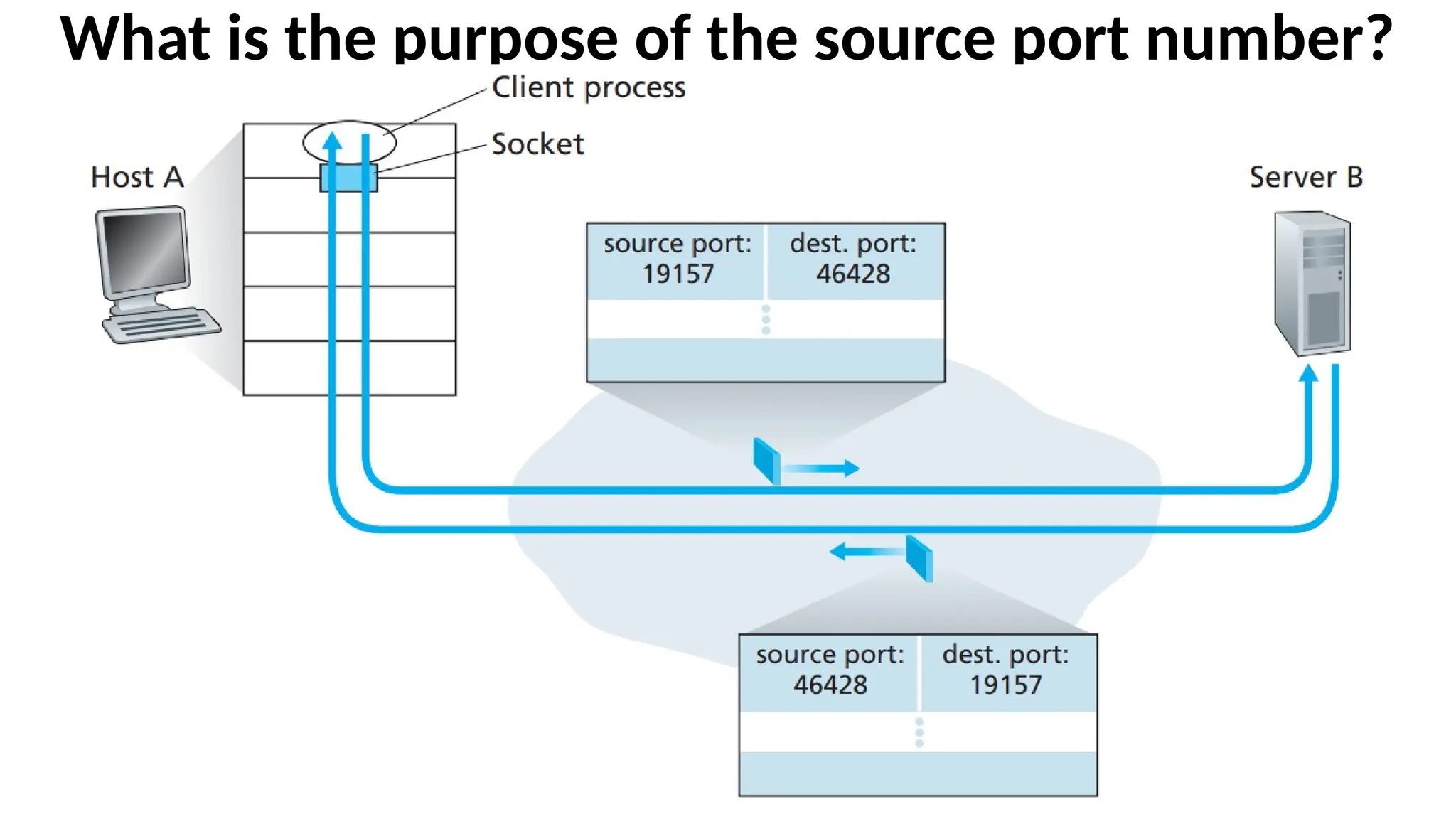
What is thepurpose of the
source port number?
•In the A-to-B segment the source port number serves as part
of a “return address”—when B wants to send a segment back
to A, the destination port in the B-to-A segment will take its
value from the source port value of the A-to-B segment.
•The server uses the recvfrom() method to extract the
clientside (source) port number from the segment it receives
from the client; it then sends a new segment to the client,
with the extracted source port number serving as the
destination port number in this new segment.
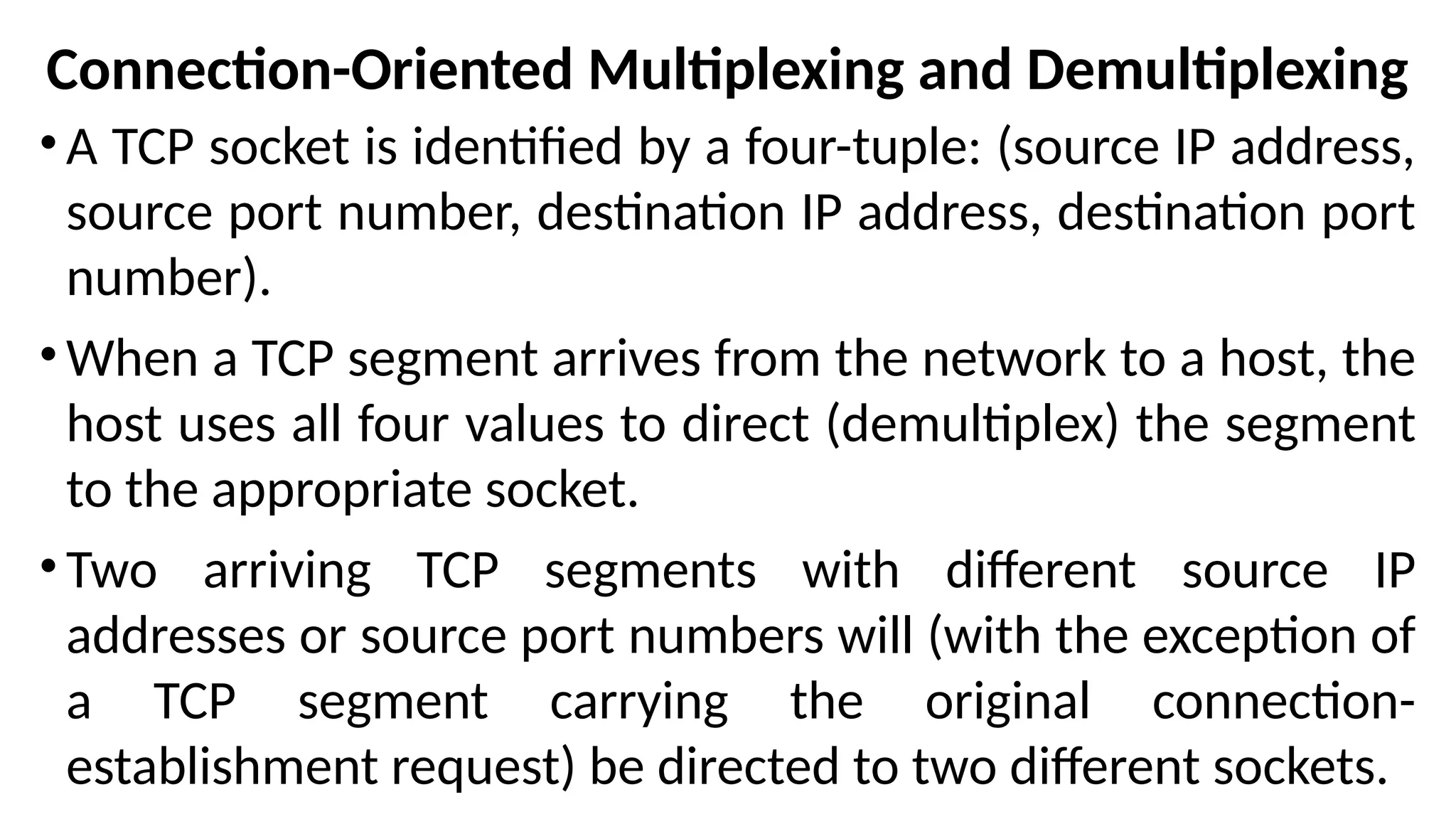
Connection-Oriented Multiplexing andDemultiplexing
•A TCP socket is identified by a four-tuple: (source IP address,
source port number, destination IP address, destination port
number).
•When a TCP segment arrives from the network to a host, the
host uses all four values to direct (demultiplex) the segment
to the appropriate socket.
•Two arriving TCP segments with different source IP
addresses or source port numbers will (with the exception of
a TCP segment carrying the original connection-
establishment request) be directed to two different sockets.
34.
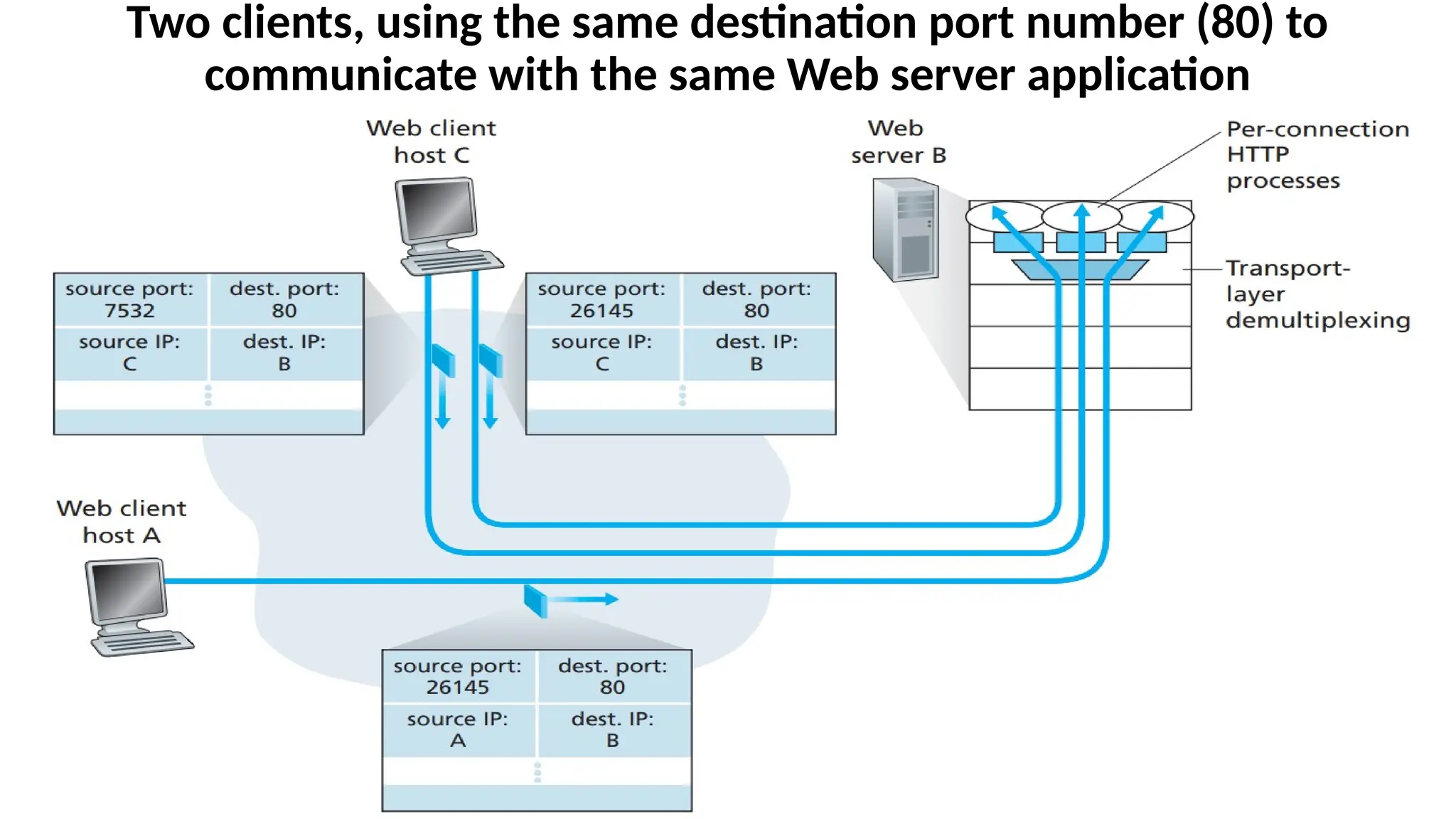
Two clients, usingthe same destination port number (80) to
communicate with the same Web server application
35.
Explanation of theDiagram
•Host C initiates two HTTP sessions to server B, and Host A
initiates one HTTP session to B.
•Hosts A and C and server B each have their own unique IP
address—A, C, and B, respectively.
•Host C assigns two different source port numbers (26145 and
7532) to its two HTTP connections. Because Host A is choosing
source port numbers independently of C, it might also assign a
source port of 26145 to its HTTP connection. But this is not a
problem—server B will still be able to correctly demultiplex
the two connections having the same source port number,
since the two connections have different source IP addresses.
SYLLABUS – MODULE2
•Introduction and Transport-Layer Services: Relationship Between Transport
and Network Layers, Overview of the Transport Layer in the Internet,
•Multiplexing and Demultiplexing:
•Connectionless Transport -- UDP: UDP Segment Structure, UDP Checksum.
•Principles of Reliable Data Transfer: Building a Reliable Data Transfer Protocol,
Pipelined Reliable Data Transfer Protocols, Go-Back-N, Selective repeat.
•Connection-Oriented Transport TCP: The TCP Connection, TCP Segment
Structure, Round- Trip Time Estimation and Timeout, Reliable Data Transfer,
Flow Control, TCP Connection Management.
•Principles of Congestion Control: The Causes and the Costs of Congestion,
Approaches to Congestion Control, Network-assisted congestion-control
example, ATM ABR Congestion control.
•TCP Congestion Control: Fairness.
Why an applicationdeveloper choose to build an
application over UDP rather than over TCP ?
Following are the Reasons:
•Finer application-level control over what data is sent,
and when.
•No connection establishment
•No connection state
•Small packet header overhead
40.
First Reason is:
Finerapplication-level control over what data is sent, and when
Under UDP, as soon as an application process passes data to UDP, UDP will
package the data inside a UDP segment and immediately pass the segment
to the network layer. TCP has a congestion-control mechanism that throttles
the transport-layer TCP sender when one or more links between the source
and destination hosts become excessively congested. TCP will also continue
to resend a segment until the receipt of the segment has been
acknowledged by the destination, regardless of how long reliable delivery
takes. Since real-time applications require a minimum sending rate, do not
want to overly delay segment transmission, and can tolerate some data
loss, TCP’s service model is not particularly well matched to these
applications’ needs. These applications can use UDP and implement, as part
of the application.
41.
Second Reason is:
Noconnection establishment
TCP uses a three-way handshake before it starts to transfer
data. UDP just blasts away without any formal preliminaries.
Thus UDP does not introduce any delay to establish a
connection. This is the principal reason why DNS runs over
UDP rather than TCP—DNS would be much slower if it ran over
TCP. HTTP uses TCP rather than UDP, since reliability is critical
for Web pages with text. The TCP connection-establishment
delay in HTTP is an important contributor to the delays
associated with downloading Web documents.
42.
Third Reason is:
Noconnection state
TCP maintains connection state in the end systems. This
connection state includes receive and send buffers,
congestion-control parameters, and sequence and
acknowledgment number parameters. This state information
is needed to implement TCP’s reliable data transfer service
and to provide congestion control. UDP, on the other hand,
does not maintain connection state and does not track any of
these parameters. For this reason, a server devoted to a
particular application can typically support many more active
clients when the application runs over UDP rather than TCP.
43.
Fourth Reason is:
Smallpacket header overhead
The TCP segment has 20 bytes of header
overhead in every segment, whereas UDP has
only 8 bytes of overhead
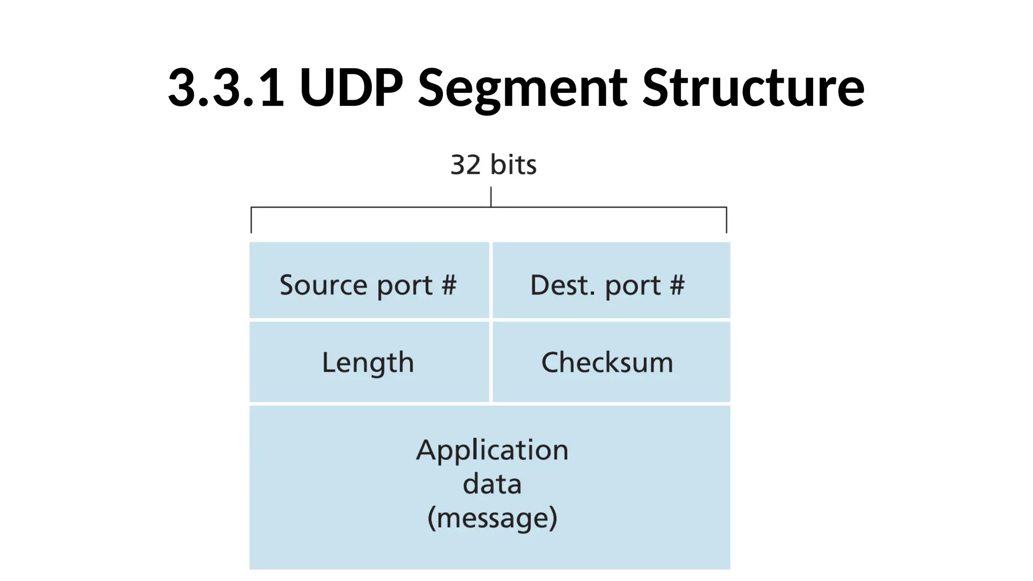
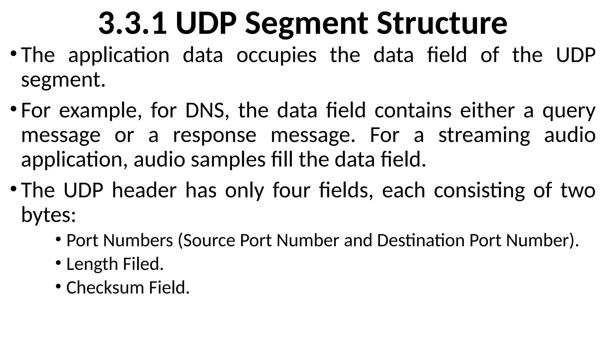
3.3.1 UDP SegmentStructure
•The application data occupies the data field of the UDP
segment.
•For example, for DNS, the data field contains either a query
message or a response message. For a streaming audio
application, audio samples fill the data field.
•The UDP header has only four fields, each consisting of two
bytes:
• Port Numbers (Source Port Number and Destination Port Number).
• Length Filed.
• Checksum Field.
46.
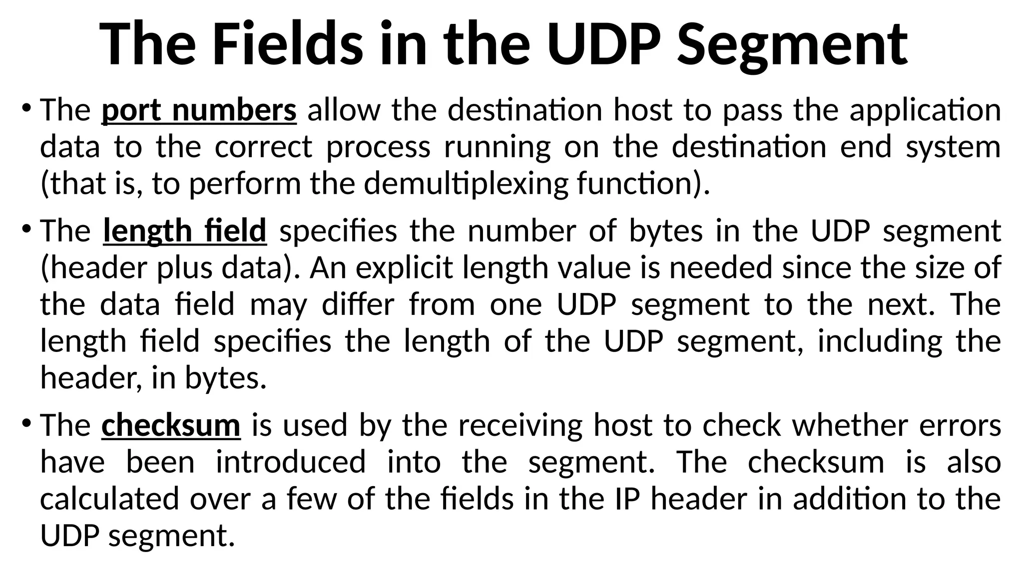
The Fields inthe UDP Segment
• The port numbers allow the destination host to pass the application
data to the correct process running on the destination end system
(that is, to perform the demultiplexing function).
• The length field specifies the number of bytes in the UDP segment
(header plus data). An explicit length value is needed since the size of
the data field may differ from one UDP segment to the next. The
length field specifies the length of the UDP segment, including the
header, in bytes.
• The checksum is used by the receiving host to check whether errors
have been introduced into the segment. The checksum is also
calculated over a few of the fields in the IP header in addition to the
UDP segment.
47.
3.3.2 UDP Checksum
•TheUDP checksum provides for error detection. That is, the
checksum is used to determine whether bits within the UDP
segment have been altered (for example, by noise in the
links or while stored in a router) as it moved from source to
destination. UDP at the sender side performs the 1’s
complement of the sum of all the 16-bit words in the
segment, with any overflow encountered during the sum
being wrapped around. This result is put in the checksum
field of the UDP segment.
48.
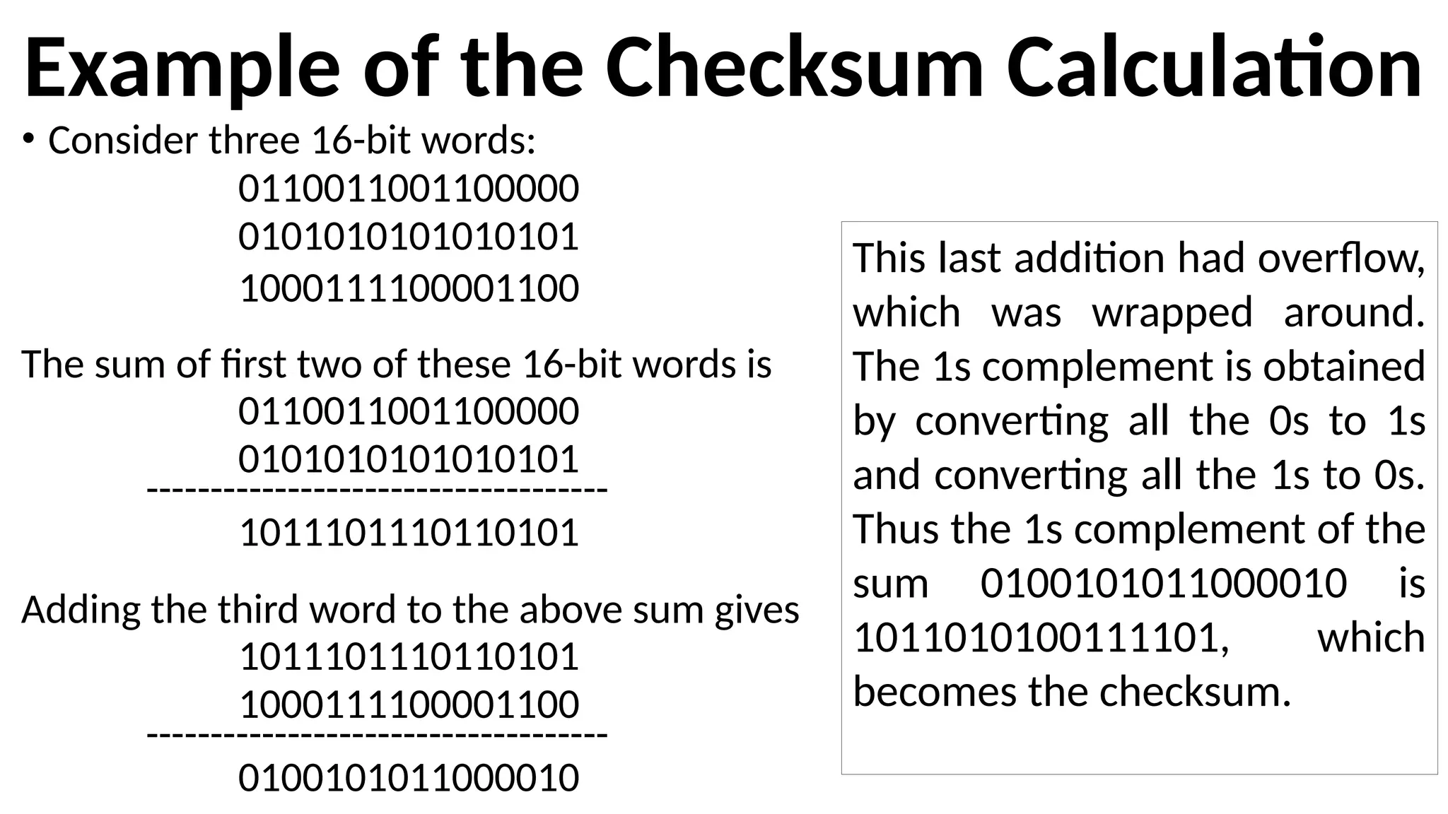
Example of theChecksum Calculation
• Consider three 16-bit words:
0110011001100000
0101010101010101
1000111100001100
The sum of first two of these 16-bit words is
0110011001100000
0101010101010101
------------------------------------
1011101110110101
Adding the third word to the above sum gives
1011101110110101
1000111100001100
------------------------------------
0100101011000010
This last addition had overflow,
which was wrapped around.
The 1s complement is obtained
by converting all the 0s to 1s
and converting all the 1s to 0s.
Thus the 1s complement of the
sum 0100101011000010 is
1011010100111101, which
becomes the checksum.
49.
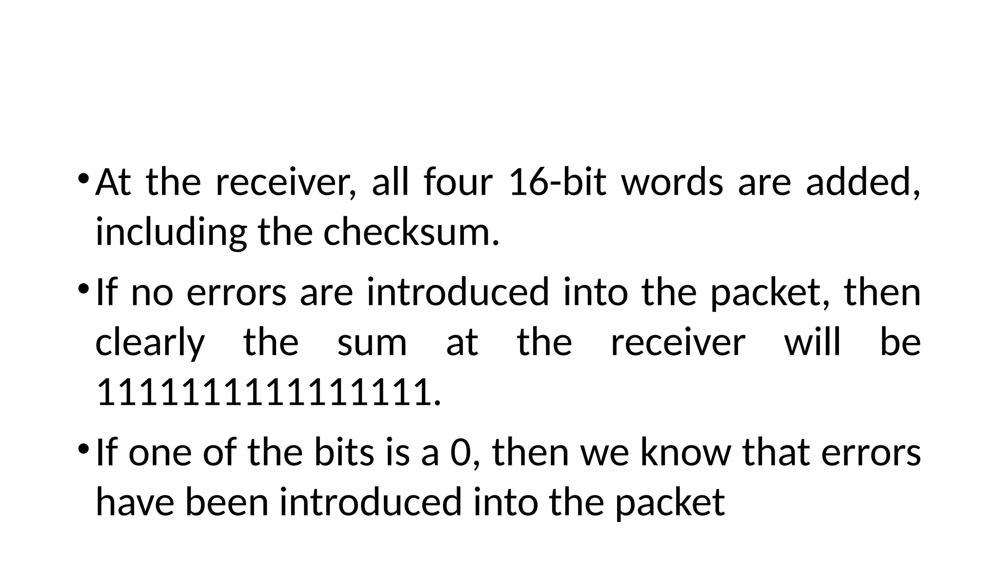
•At the receiver,all four 16-bit words are added,
including the checksum.
•If no errors are introduced into the packet, then
clearly the sum at the receiver will be
1111111111111111.
•If one of the bits is a 0, then we know that errors
have been introduced into the packet
SYLLABUS – MODULE2
•Introduction and Transport-Layer Services: Relationship Between Transport
and Network Layers, Overview of the Transport Layer in the Internet,
•Multiplexing and Demultiplexing:
•Connectionless Transport -- UDP: UDP Segment Structure, UDP Checksum.
•Principles of Reliable Data Transfer: Building a Reliable Data Transfer Protocol,
Pipelined Reliable Data Transfer Protocols, Go-Back-N, Selective repeat.
•Connection-Oriented Transport TCP: The TCP Connection, TCP Segment
Structure, Round- Trip Time Estimation and Timeout, Reliable Data Transfer,
Flow Control, TCP Connection Management.
•Principles of Congestion Control: The Causes and the Costs of Congestion,
Approaches to Congestion Control, Network-assisted congestion-control
example, ATM ABR Congestion control.
•TCP Congestion Control: Fairness.
52.
3.4 Principles ofReliable Data Transfer
Syllabus
•Building a Reliable Data Transfer Protocol.
• Pipelined Reliable Data Transfer Protocols.
• Go-Back-N.
•Selective repeat.
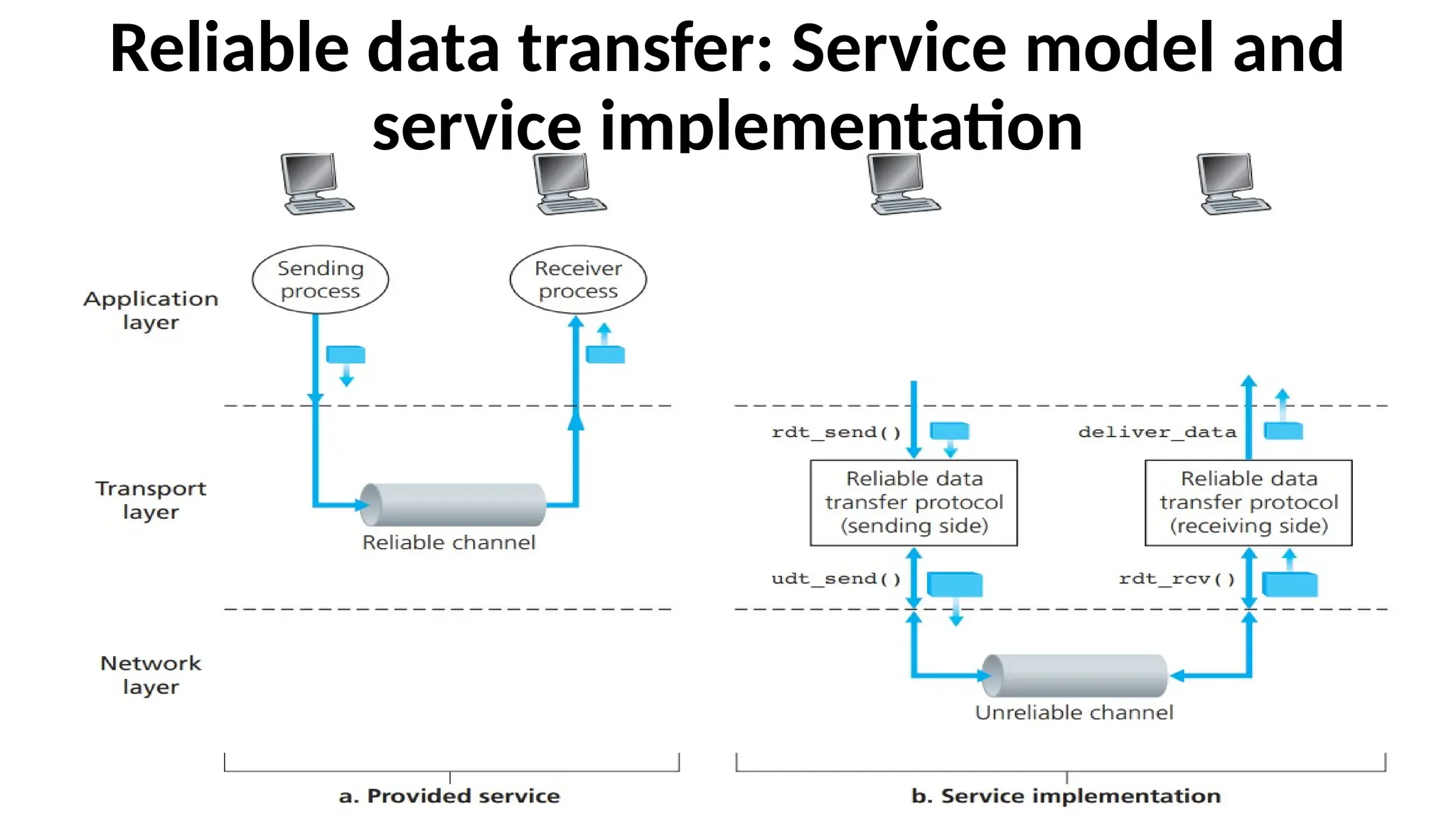
Reliable data transfer:Service model and
service implementation
• The service abstraction provided to the upper-layer entities is
that of a reliable channel through which data can be
transferred.
• With a reliable channel, no transferred data bits are corrupted
(flipped from 0 to 1, or vice versa) or lost, and all are delivered
in the order in which they were sent.
• It is the responsibility of a reliable data transfer protocol to
implement this service abstraction. This task is made difficult by
the fact that the layer below the reliable data transfer protocol
may be unreliable.
55.
Example
•TCP is areliable data transfer protocol that is
implemented on top of an unreliable (IP) end-to-end
network layer.
•The layer beneath the two reliably communicating end
points might consist of a single physical link (as in the
case of a link-level data transfer protocol) or a global
internetwork (as in the case of a transport-level
protocol). This lower layer is an unreliable point-to-
point channel.
56.
Sending Side ofthe Data Transfer Protocol
•The sending side of the data transfer protocol will be
invoked from above by a call to rdt_send().
•It will pass the data to be delivered to the upper layer
at the receiving side.
•Here rdt stands for reliable data transfer protocol
and _send indicates that the sending side of rdt is
being called.
57.
Receiving Side ofthe Data Transfer Protocol
•On the receiving side, rdt_rcv() will be called when
a packet arrives from the receiving side of the channel.
•When the rdt protocol wants to deliver data to the
upper layer, it will do so by calling deliver_data()
•Both the send and receive sides of rdt send packets to
the other side by a call to udt_send() (where udt
stands for unreliable data transfer).
58.
3.4.1 Building aReliable Data Transfer Protocol
•Reliable Data Transfer over a Perfectly Reliable Channel: rdt1.0
•Reliable Data Transfer over a Channel with Bit Errors: rdt2.0
• Reliable Data Transfer over a Lossy Channel with Bit Errors: rdt3.0
59.
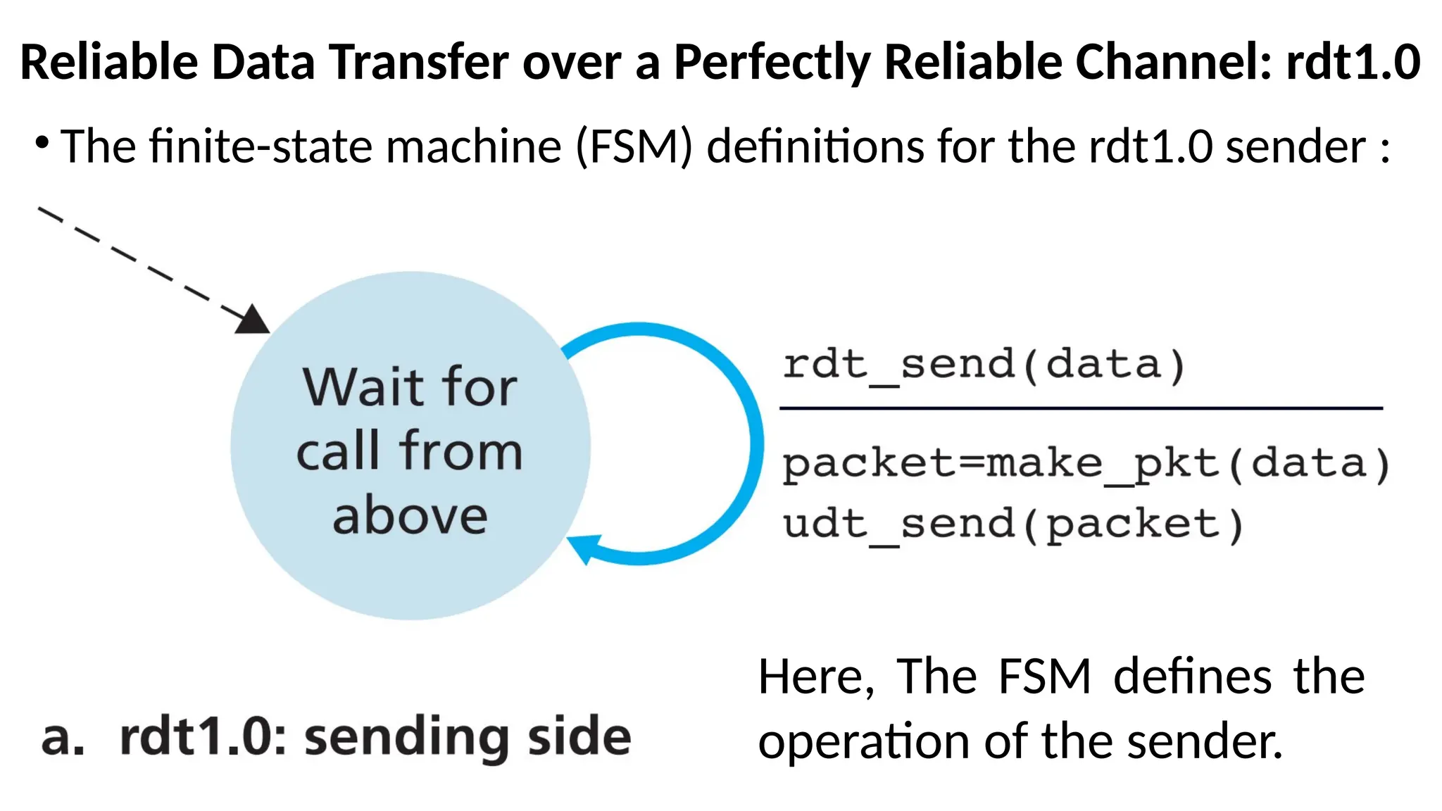
Reliable Data Transferover a Perfectly Reliable Channel: rdt1.0
• The finite-state machine (FSM) definitions for the rdt1.0 sender :
Here, The FSM defines the
operation of the sender.
60.
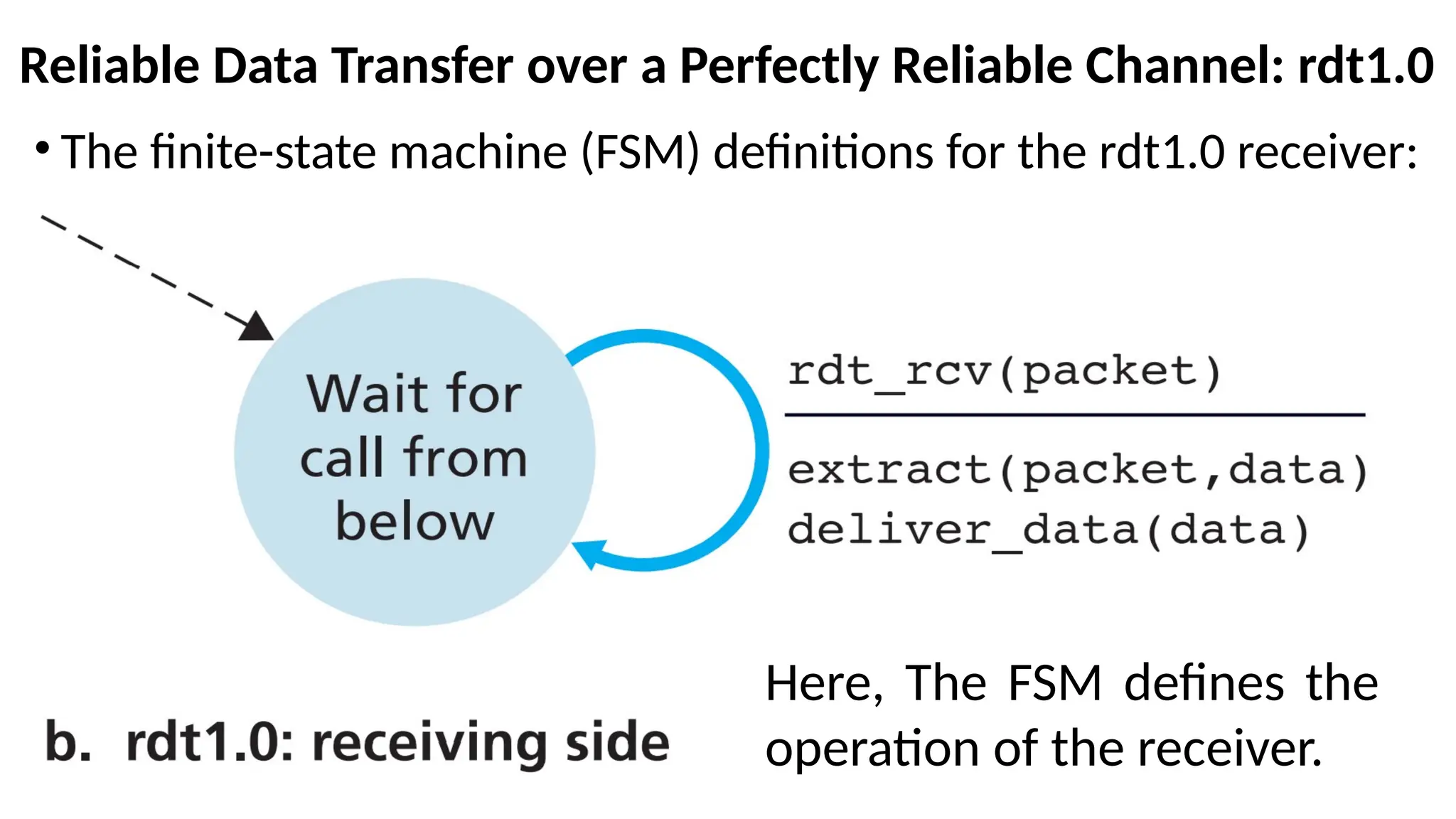
Reliable Data Transferover a Perfectly Reliable Channel: rdt1.0
• The finite-state machine (FSM) definitions for the rdt1.0 receiver:
Here, The FSM defines the
operation of the receiver.
61.
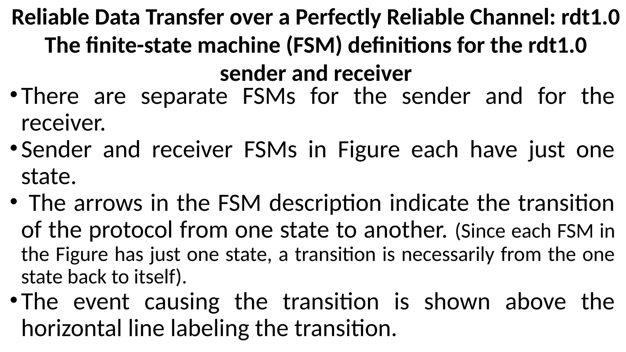
Reliable Data Transferover a Perfectly Reliable Channel: rdt1.0
The finite-state machine (FSM) definitions for the rdt1.0
sender and receiver
•There are separate FSMs for the sender and for the
receiver.
•Sender and receiver FSMs in Figure each have just one
state.
• The arrows in the FSM description indicate the transition
of the protocol from one state to another. (Since each FSM in
the Figure has just one state, a transition is necessarily from the one
state back to itself).
•The event causing the transition is shown above the
horizontal line labeling the transition.
62.
Reliable Data Transferover a Perfectly Reliable Channel: rdt1.0
The finite-state machine (FSM) definitions for the rdt1.0
sender and receiver
•The actions taken when the event occurs are shown below
the horizontal line.
•When no action is taken on an event, or no event occurs
and an action is taken, we’ll use the symbol below or
above the horizontal, respectively, to explicitly denote the
lack of an action or event.
•The initial state of the FSM is indicated by the dashed
arrow.
Contd…
63.
Reliable Data Transferover a Perfectly Reliable Channel: rdt1.0
On Sender side Operation
•The sending side of rdt simply accepts data from the
upper layer via the rdt_send(data) event, creates a packet
containing the data (via the action make_pkt(data)) and
sends the packet into the channel.
•In practice, the rdt_send(data) event would result from a
procedure call (for example, to rdt_send()) by the upper-
layer application.
64.
Reliable Data Transferover a Perfectly Reliable Channel: rdt1.0
On Reciever side Operation
•On the receiving side, rdt receives a packet from the
underlying channel via the rdt_rcv(packet) event, removes
the data from the packet (via the action extract (packet,
data)), passes the data up to the upper layer (via the action
deliver_data(data)).
•In practice, the rdt_rcv(packet) event would result from a
procedure call (for example, to rdt_rcv()) from the lower-
layer protocol.
65.
Reliable Data Transferover a Channel with Bit Errors: rdt2.0
•A more realistic model of the underlying channel is one
in which bits in a packet may be corrupted. Such bit
errors occur in the physical components of a network
as a packet is transmitted, propagates, or is buffered.
•Assume for the moment that all transmitted packets
are received (although their bits may be corrupted) in
the order in which they were sent.
66.
The Control Messages
•TwoTypes:
•Positive Acknowledgments (“OK”) and
•Negative Acknowledgments (“Please repeat that.”).
•These control messages allow the receiver to let the sender
know what has been received correctly, and what has been
received in error and thus requires repeating. In a computer
network setting, reliable data transfer protocols based on
such retransmission are known as ARQ (Automatic Repeat
reQuest) protocols.
67.
Three additional protocolcapabilities
are required in ARQ protocols to
handle the presence of bit errors
•Error detection
•Receiver feedback
•Retransmission
68.
Error Detection
•A mechanismis needed to allow the
receiver to detect when bit errors have
occurred.
•UDP uses the Internet checksum field for
exactly this purpose.
69.
Receiver feedback
• Sincethe sender and receiver are executing on different end
systems, the only way for the sender to learn of the
receiver’s view of the world is for the receiver to provide
explicit feedback to the sender. The positive (ACK) and
negative (NAK) acknowledgment replies in the message-
dictation scenario are examples of such feedback. Our rdt2.0
protocol will similarly send ACK and NAK packets back from
the receiver to the sender. In principle, these packets need
only be one bit long; for example, a 0 value could indicate a
NAK and a value of 1 could indicate an ACK.
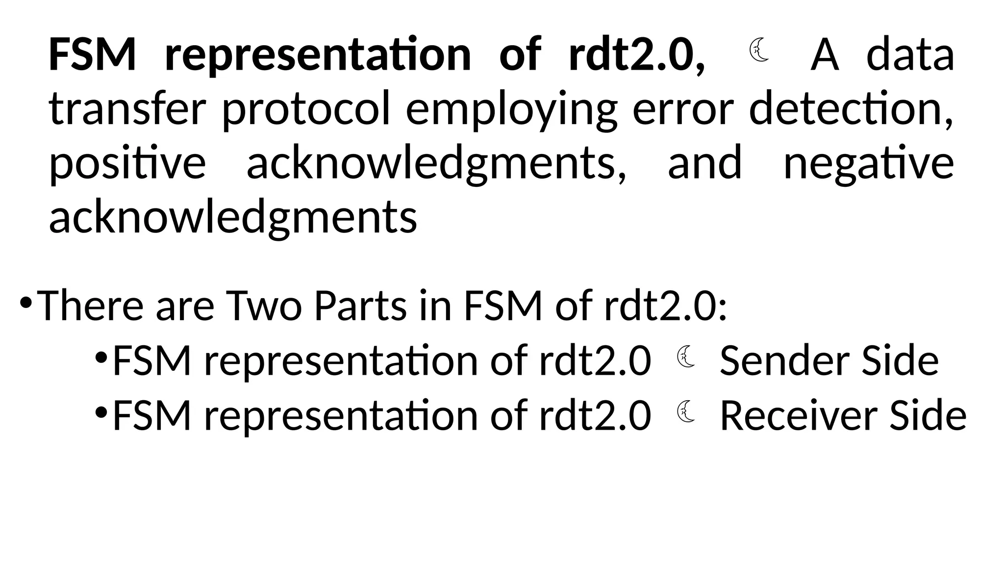
FSM representation ofrdt2.0, A data
transfer protocol employing error detection,
positive acknowledgments, and negative
acknowledgments
•There are Two Parts in FSM of rdt2.0:
•FSM representation of rdt2.0 Sender Side
•FSM representation of rdt2.0 Receiver Side
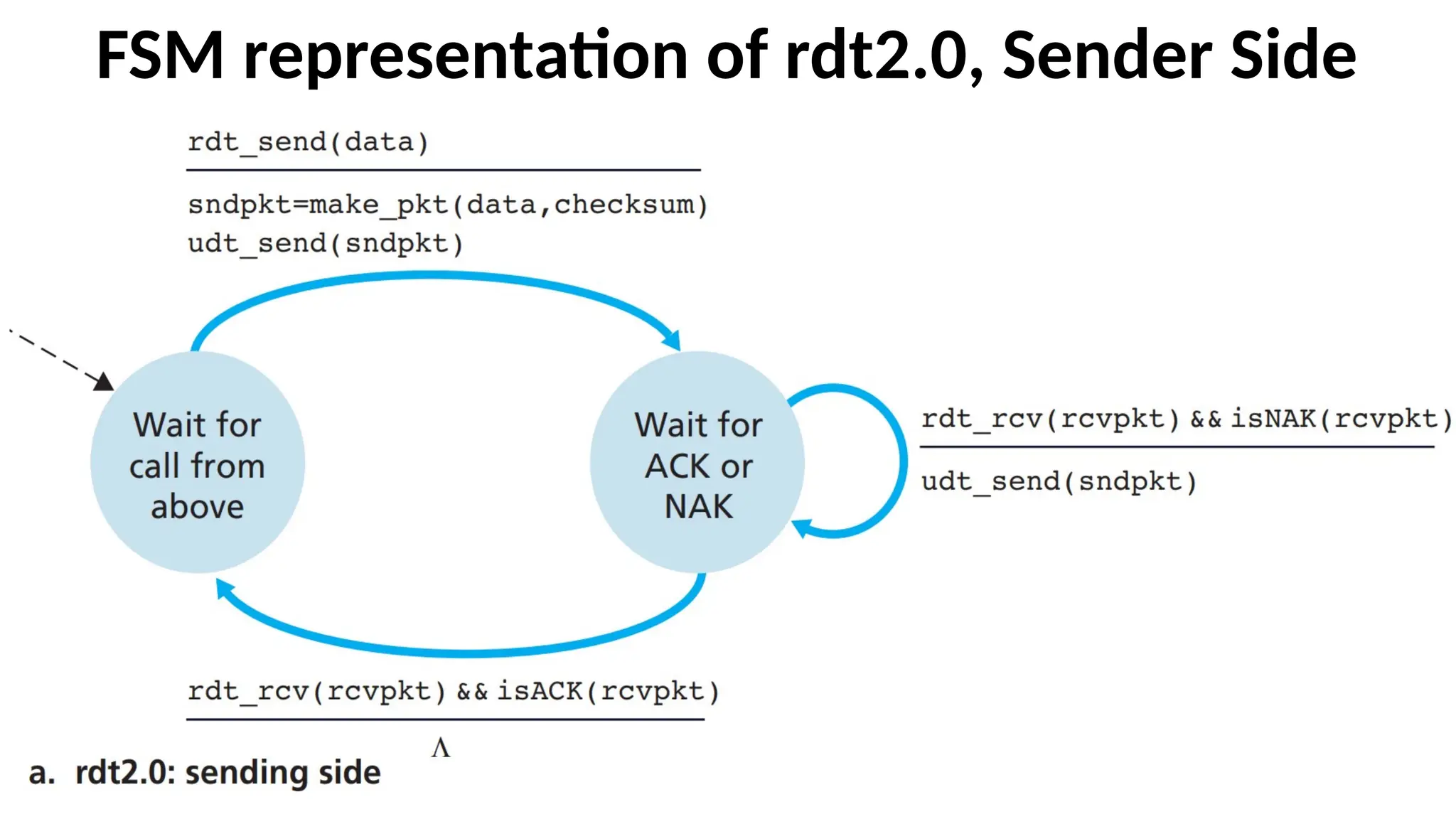
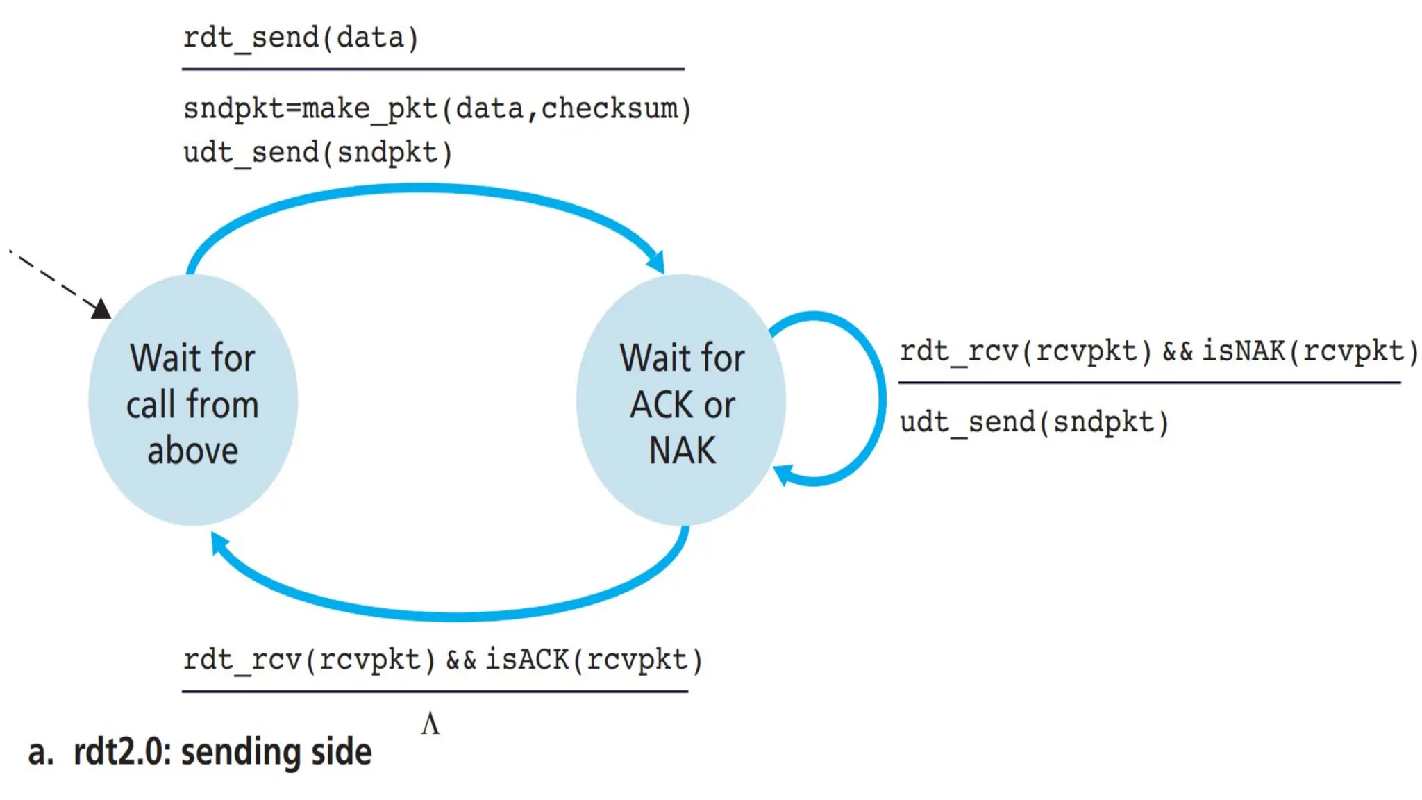
Explanation -- Thesend side of rdt2.0
•The send side of rdt2.0 has two states.
•Left Most State and
•Right Most State
75.
The send sideof rdt2.0 – Left Most State
•In the leftmost state, the send-side protocol is waiting
for data to be passed down from the upper layer.
•When the rdt_send(data) event occurs, the sender will
create a packet (sndpkt) containing the data to be sent,
along with a packet checksum and then send the packet
via the udt_send(sndpkt) operation.
76.
The send sideof rdt2.0 – Right Most State
•In the rightmost state, the sender protocol
is waiting for
•An ACK or
•A NAK packet
from the receiver.
77.
If an ACKpacket is received
•In the figure, ACK Packet is represented by the notation
rdt_rcv(rcvpkt) && isACK (rcvpkt)
•If an ACK packet is received, the sender knows that the
most recently transmitted packet has been received
correctly and thus the protocol returns to the state of
waiting for data from the upper layer.
78.
If a NAKis received
•If a NAK is received, the protocol retransmits
the last packet and waits for an ACK or NAK to
be returned by the receiver in response to the
retransmitted data packet.
79.
Stop-and Wait Protocols
•Whenthe sender is in the wait-for-ACK-or-NAK state,
it cannot get more data from the upper layer; that is,
the rdt_send() event can not occur; that will
happen only after the sender receives an ACK and
leaves this state.
•Thus, the sender will not send a new piece of data until
it is sure that the receiver has correctly received the
current packet. Because of this behavior, protocols such
as rdt2.0 are known as stop-and-wait protocols.
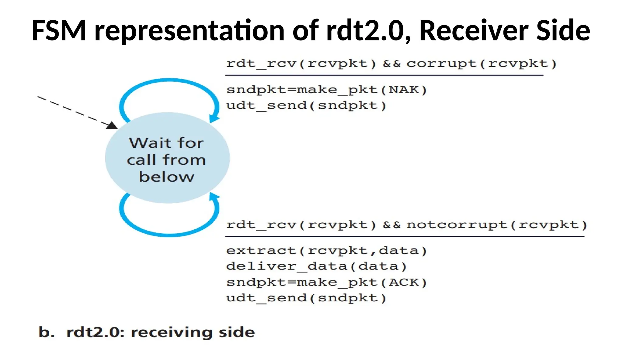
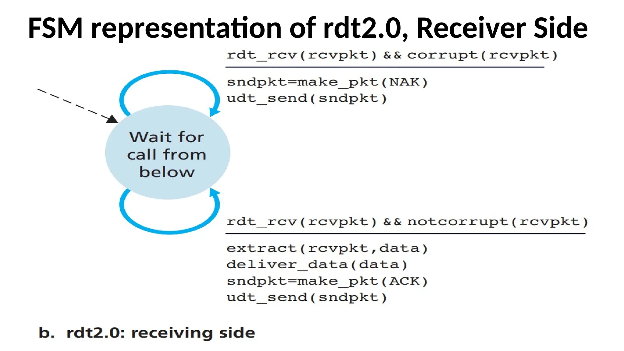
•The receiver-side FSMfor rdt2.0 has a single state.
•On packet arrival, the receiver replies with either
an ACK or a NAK, depending on whether the
received packet is corrupted or not.
•In Figure, the event that a packet is received and is
found to be in error is denoted by the notation:
rdt_rcv(rcvpkt) && corrupt(rcvpkt)
84.
Problem with rdt2.0(Stop-and-Wait) protocol
•If an ACK or NAK is corrupted, the sender has
no way of knowing whether or not the
receiver has correctly received the last piece
of transmitted data.
85.
Solution to theProblem
•Add a new field to the data packet and have
the sender number its data packets by
putting a sequence number into this field.
The receiver then need only check this
sequence number to determine whether or
not the received packet is a retransmission.
86.
FSM for rdt2.1
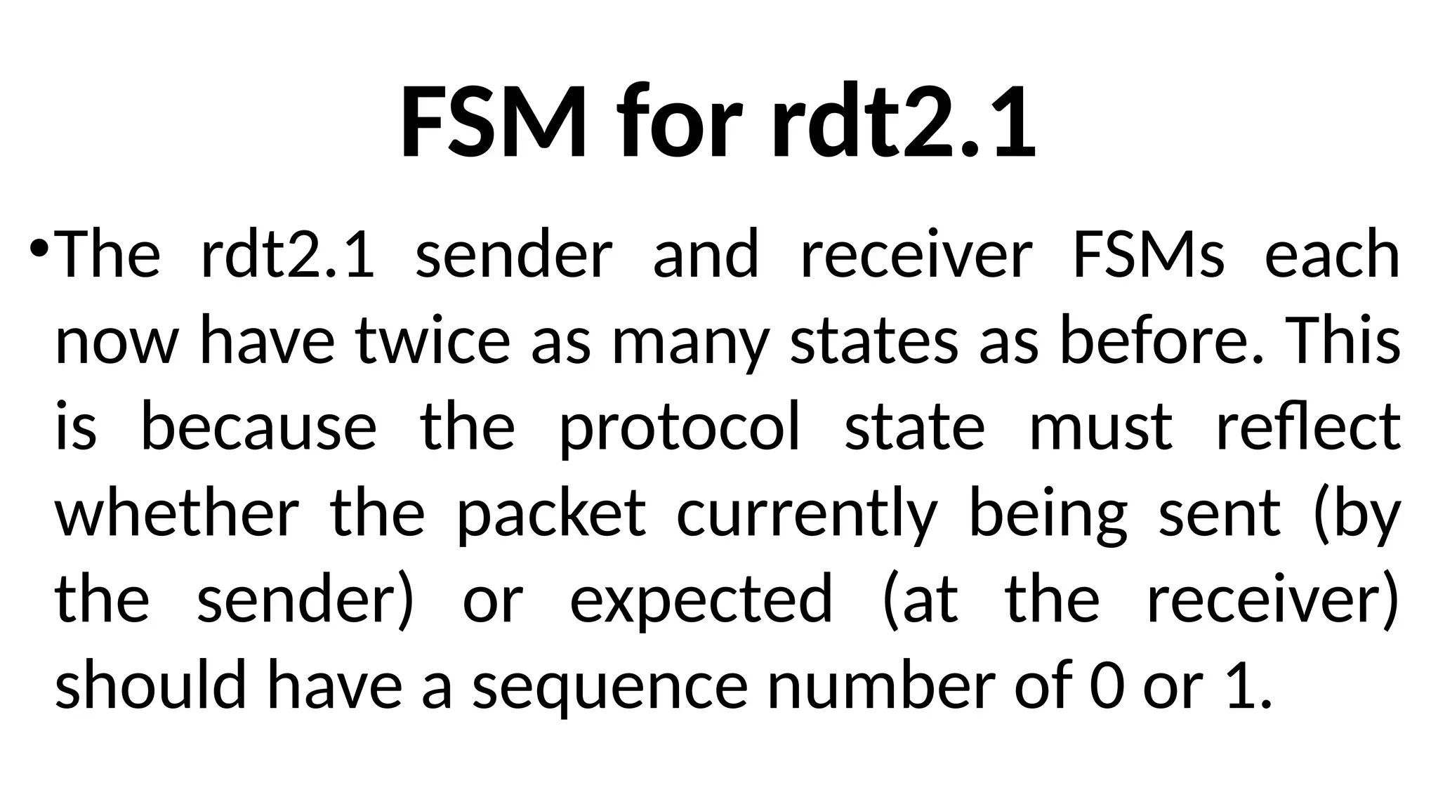
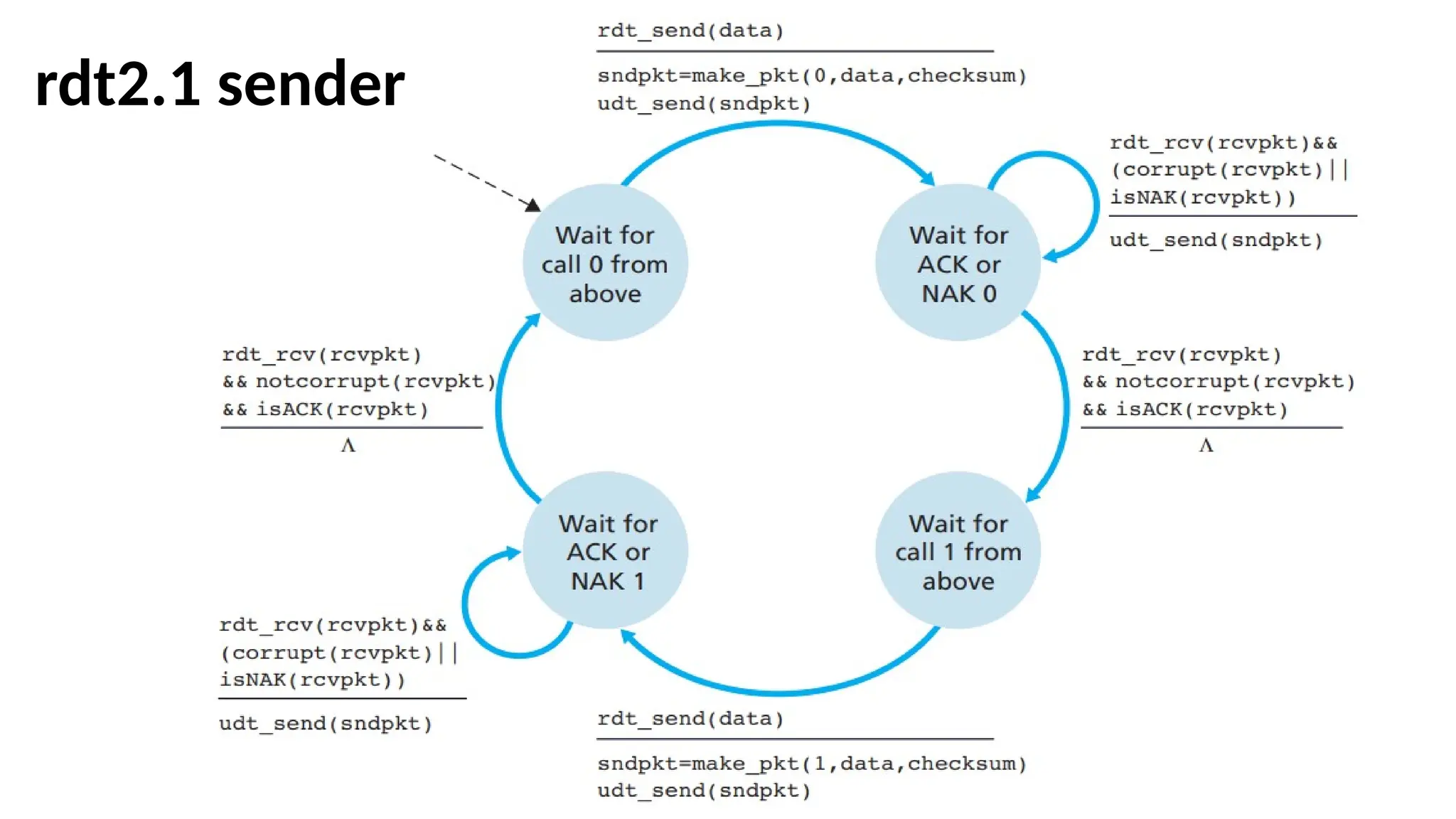
•Therdt2.1 sender and receiver FSMs each
now have twice as many states as before. This
is because the protocol state must reflect
whether the packet currently being sent (by
the sender) or expected (at the receiver)
should have a sequence number of 0 or 1.
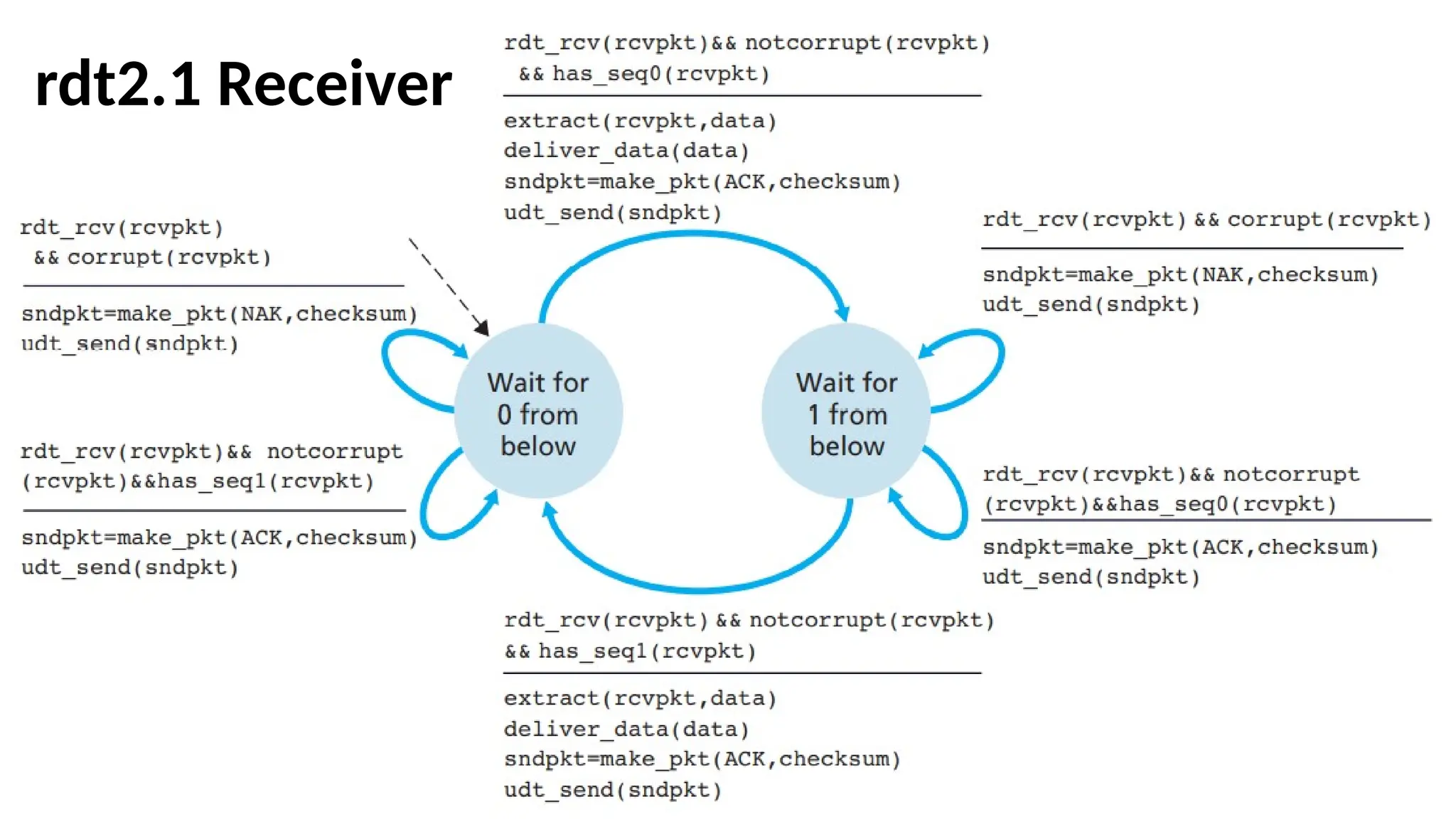
•Protocol rdt2.1 usesboth positive and
negative acknowledgments from the receiver
to the sender.
•When an out-of-order packet is received, the
receiver sends a positive acknowledgment for
the packet it has received.
•When a corrupted packet is received, the
receiver sends a negative acknowledgment.
90.
rdt3.0 Protocol
•This Protocolreliably transfers data over a
channel that can corrupt or lose packets.
•There are four cases in operations.
• rdt3.0 Operation with no loss
91.
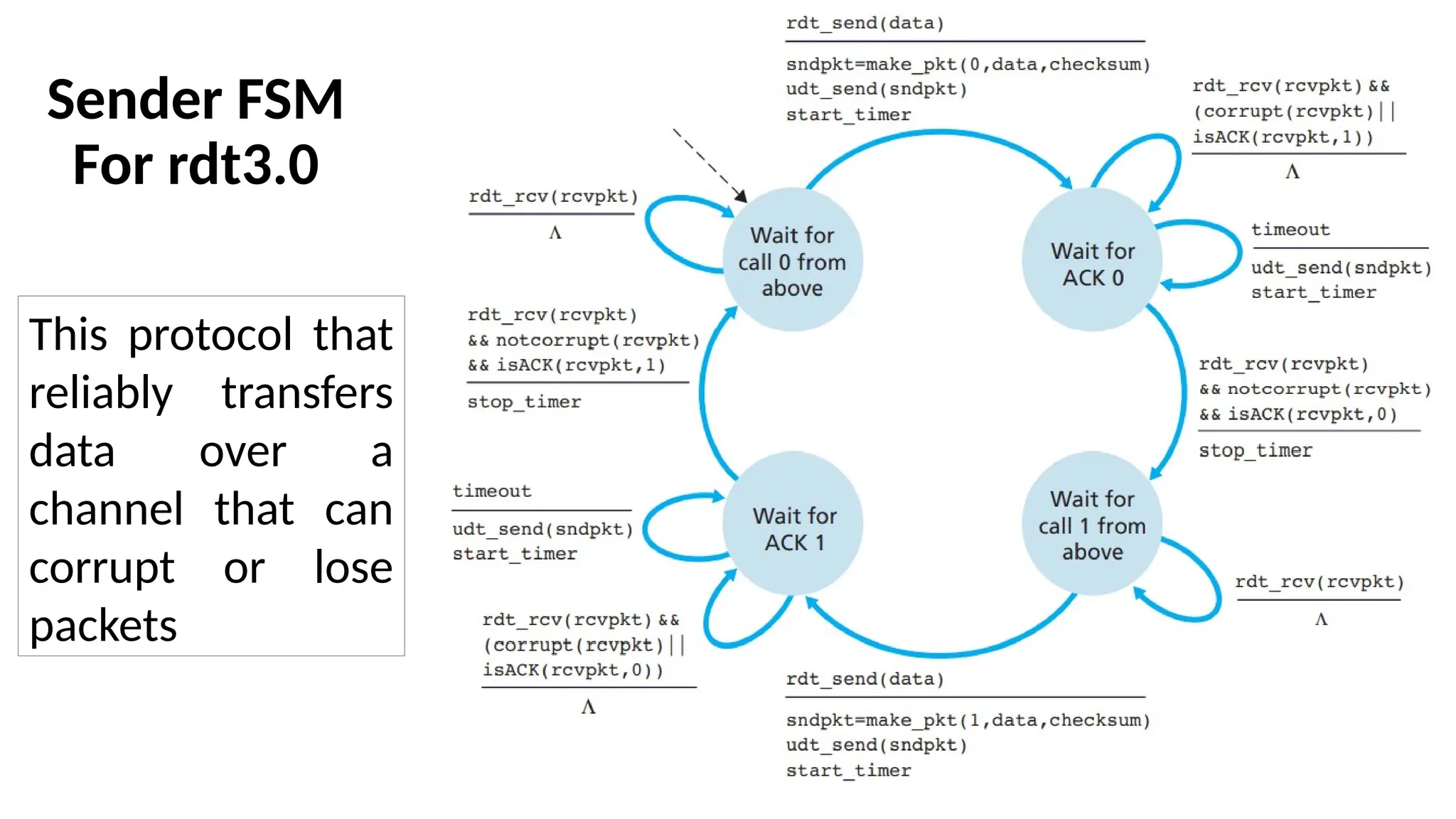
Sender FSM
For rdt3.0
Thisprotocol that
reliably transfers
data over a
channel that can
corrupt or lose
packets
92.
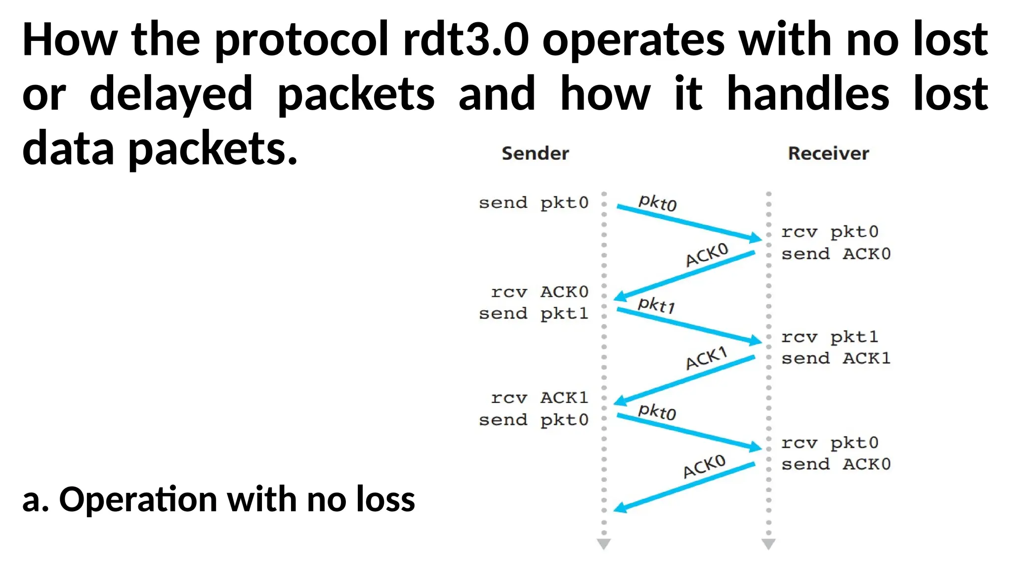
How the protocolrdt3.0 operates with no lost
or delayed packets and how it handles lost
data packets.
a. Operation with no loss
93.
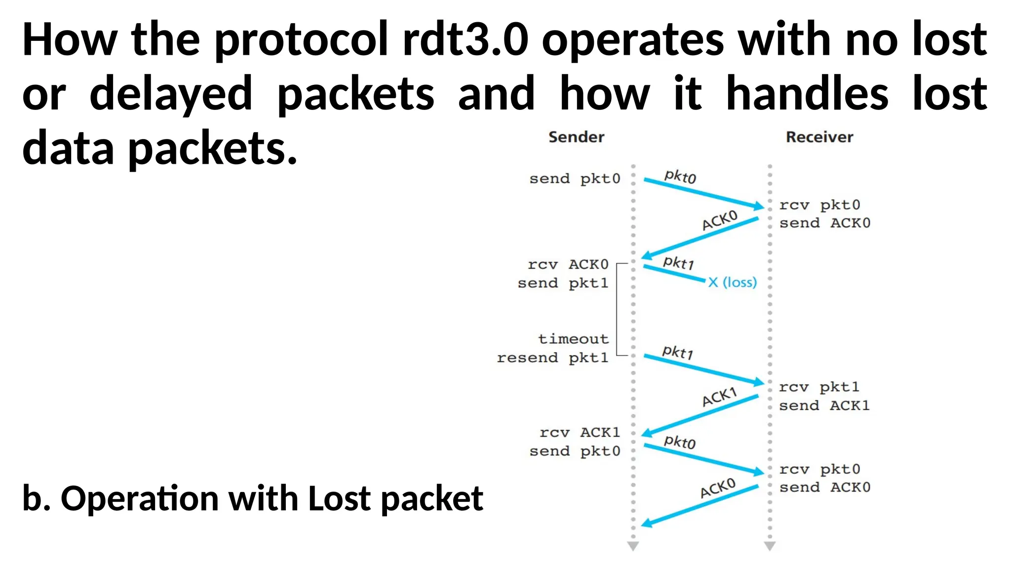
How the protocolrdt3.0 operates with no lost
or delayed packets and how it handles lost
data packets.
b. Operation with Lost packet
94.
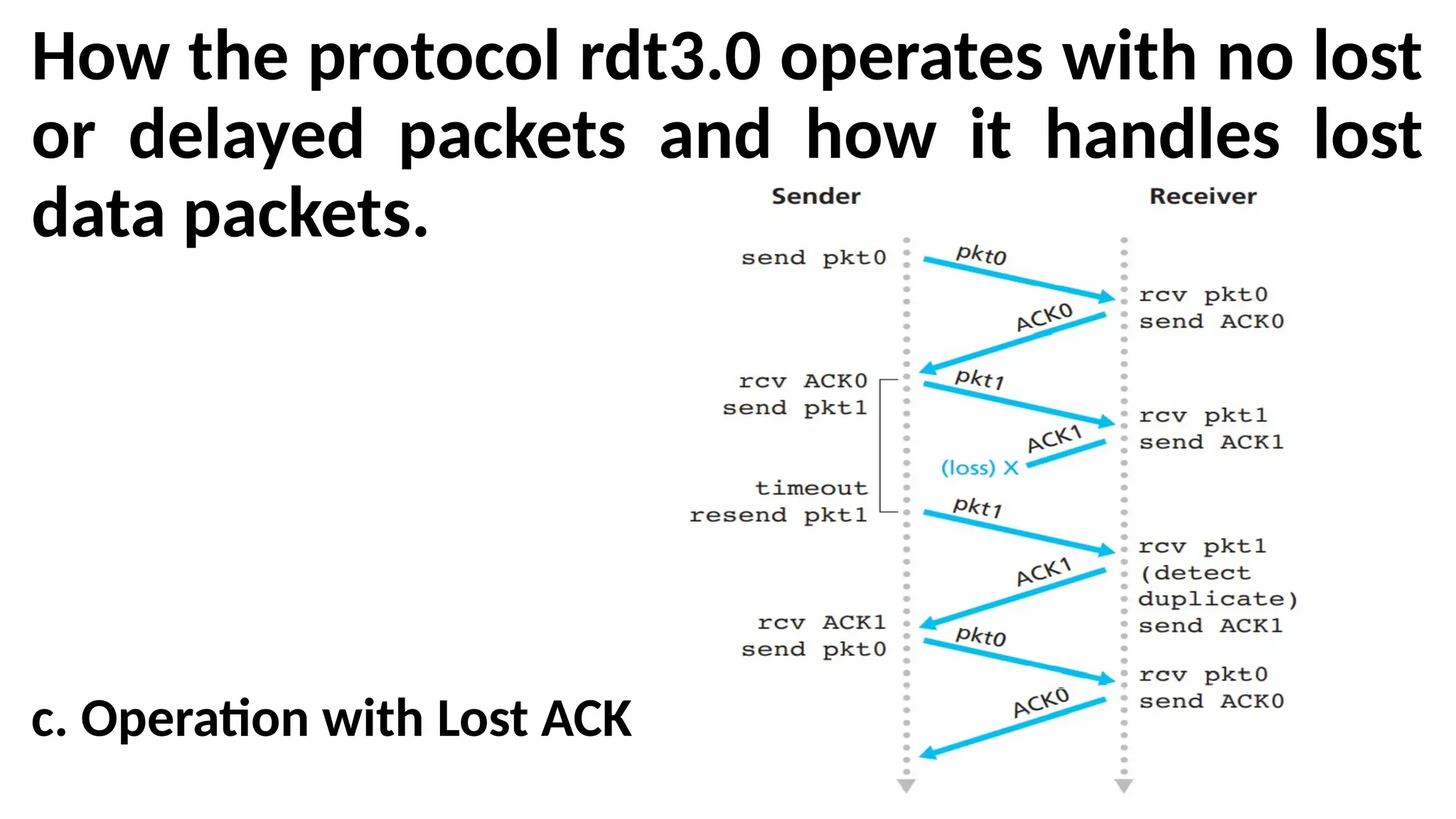
How the protocolrdt3.0 operates with no lost
or delayed packets and how it handles lost
data packets.
c. Operation with Lost ACK
95.
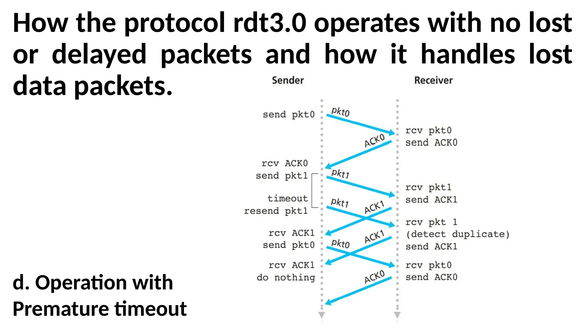
How the protocolrdt3.0 operates with no lost
or delayed packets and how it handles lost
data packets.
d. Operation with
Premature timeout
96.
Alternating-Bit Protocol
•The timemoves forward from the top of the diagram
toward the bottom of the diagram.
•A receive time for a packet is necessarily later than
the send time for a packet as a result of transmission
and propagation delays.
•In Figures (b)–(d), the send-side brackets indicate the
times at which a timer is set and later times out.
•Because packet sequence numbers alternate
between 0 and 1, protocol rdt3.0 is sometimes
known as the alternating-bit protocol.
97.
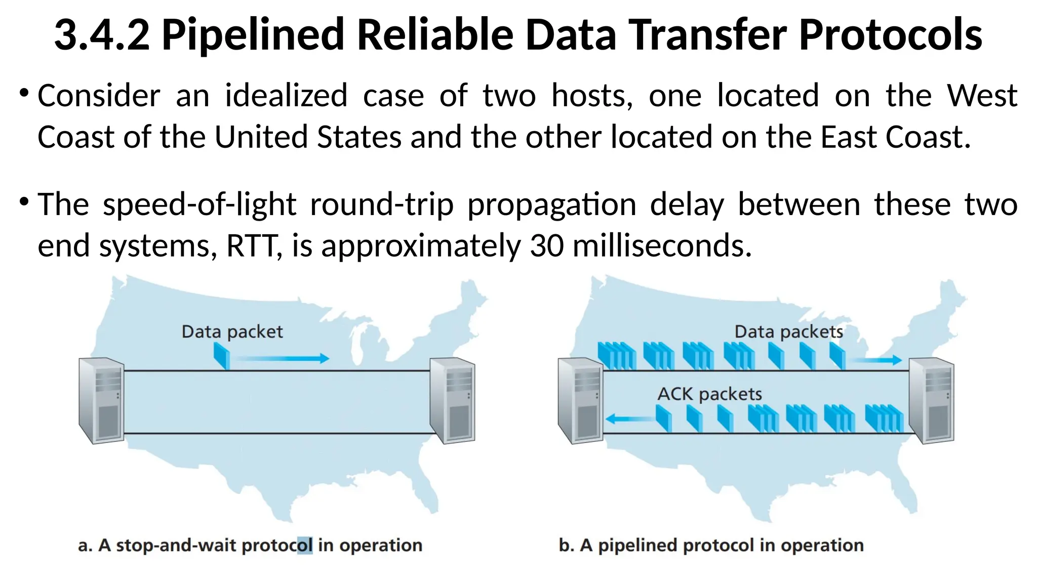
3.4.2 Pipelined ReliableData Transfer Protocols
• Consider an idealized case of two hosts, one located on the West
Coast of the United States and the other located on the East Coast.
• The speed-of-light round-trip propagation delay between these two
end systems, RTT, is approximately 30 milliseconds.
98.
3.4.2 Pipelined ReliableData Transfer Protocols
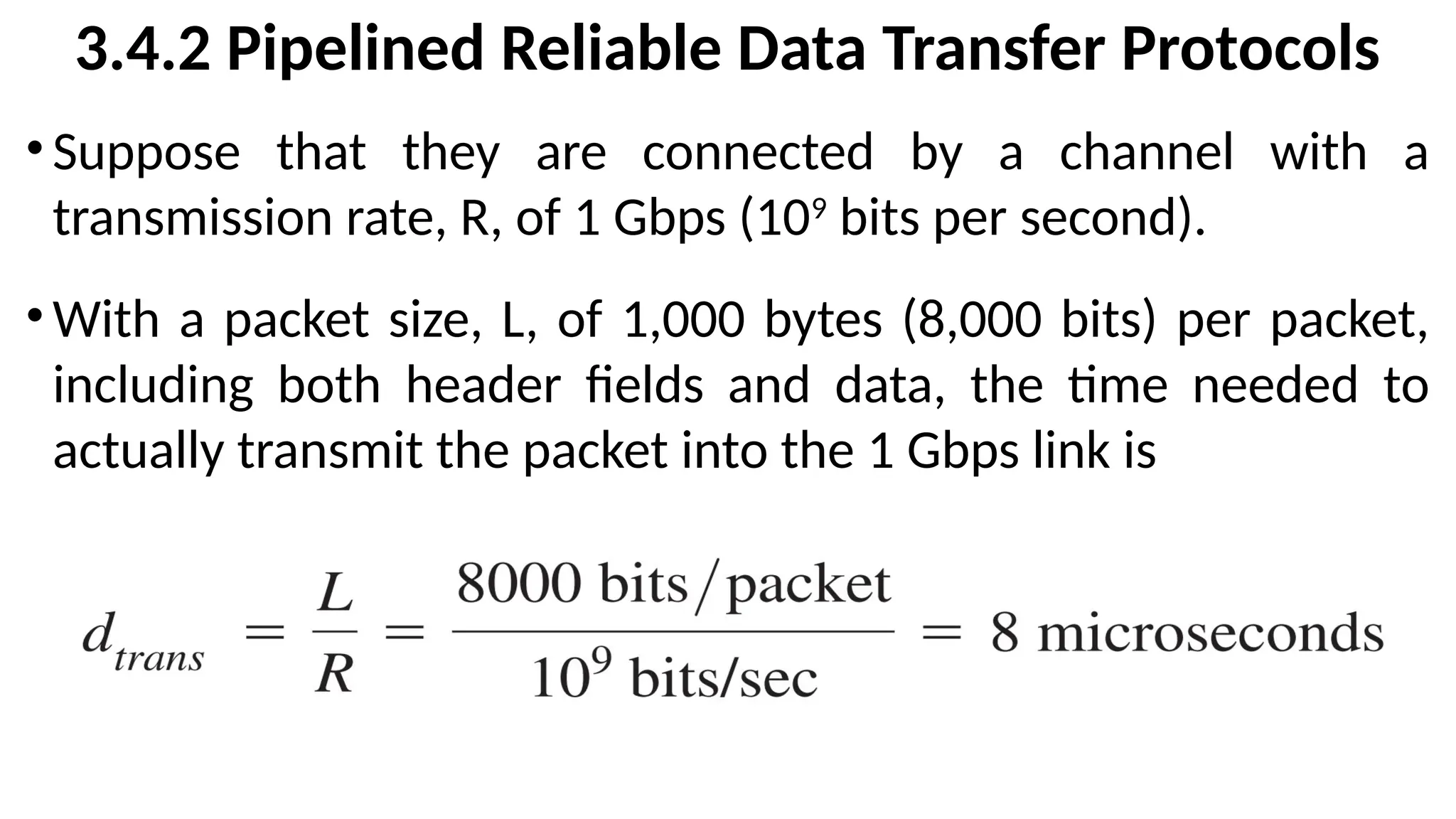
•Suppose that they are connected by a channel with a
transmission rate, R, of 1 Gbps (109
bits per second).
•With a packet size, L, of 1,000 bytes (8,000 bits) per packet,
including both header fields and data, the time needed to
actually transmit the packet into the 1 Gbps link is
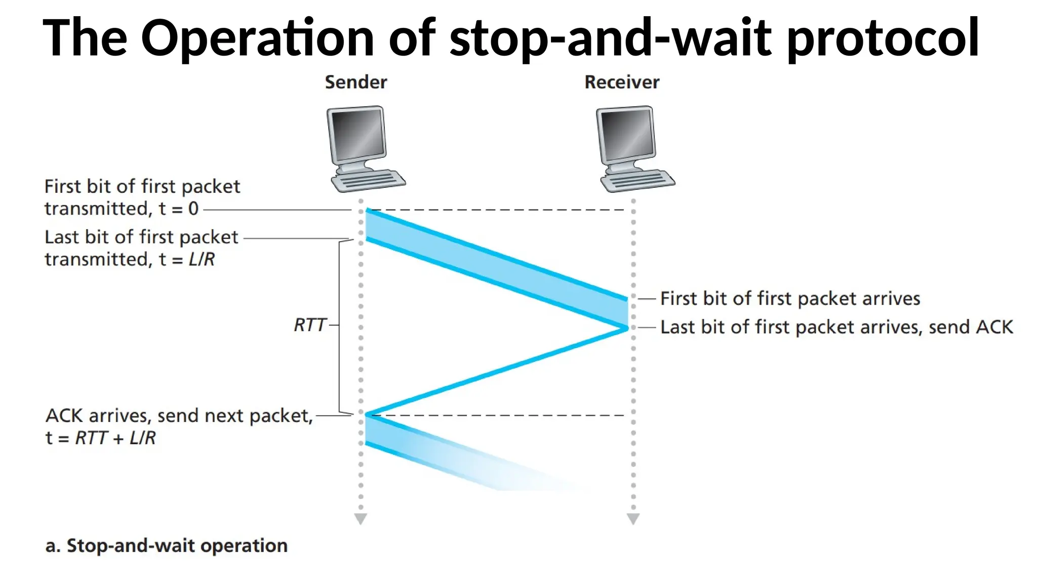
The Operation ofstop-and-wait protocol
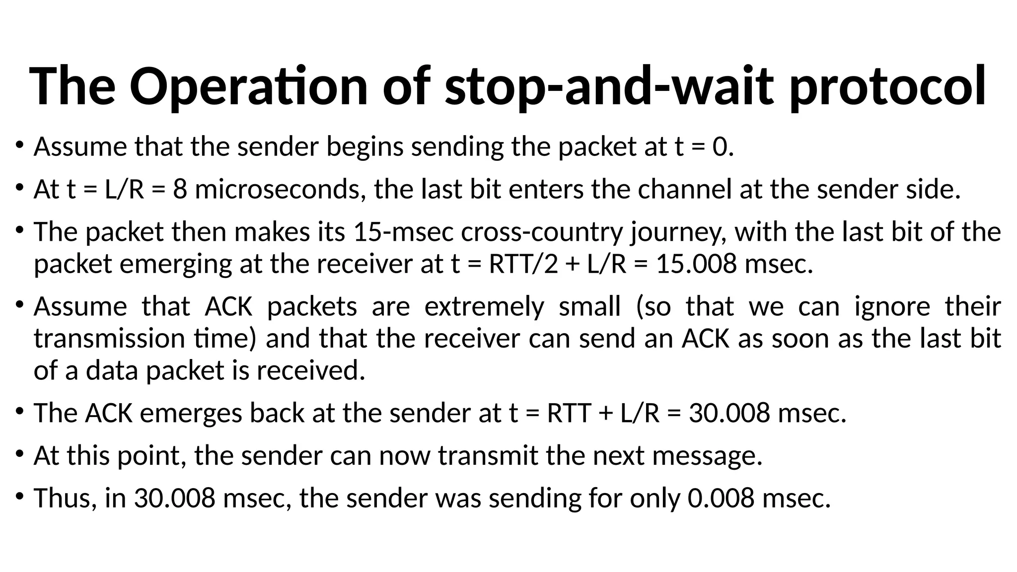
• Assume that the sender begins sending the packet at t = 0.
• At t = L/R = 8 microseconds, the last bit enters the channel at the sender side.
• The packet then makes its 15-msec cross-country journey, with the last bit of the
packet emerging at the receiver at t = RTT/2 + L/R = 15.008 msec.
• Assume that ACK packets are extremely small (so that we can ignore their
transmission time) and that the receiver can send an ACK as soon as the last bit
of a data packet is received.
• The ACK emerges back at the sender at t = RTT + L/R = 30.008 msec.
• At this point, the sender can now transmit the next message.
• Thus, in 30.008 msec, the sender was sending for only 0.008 msec.
101.
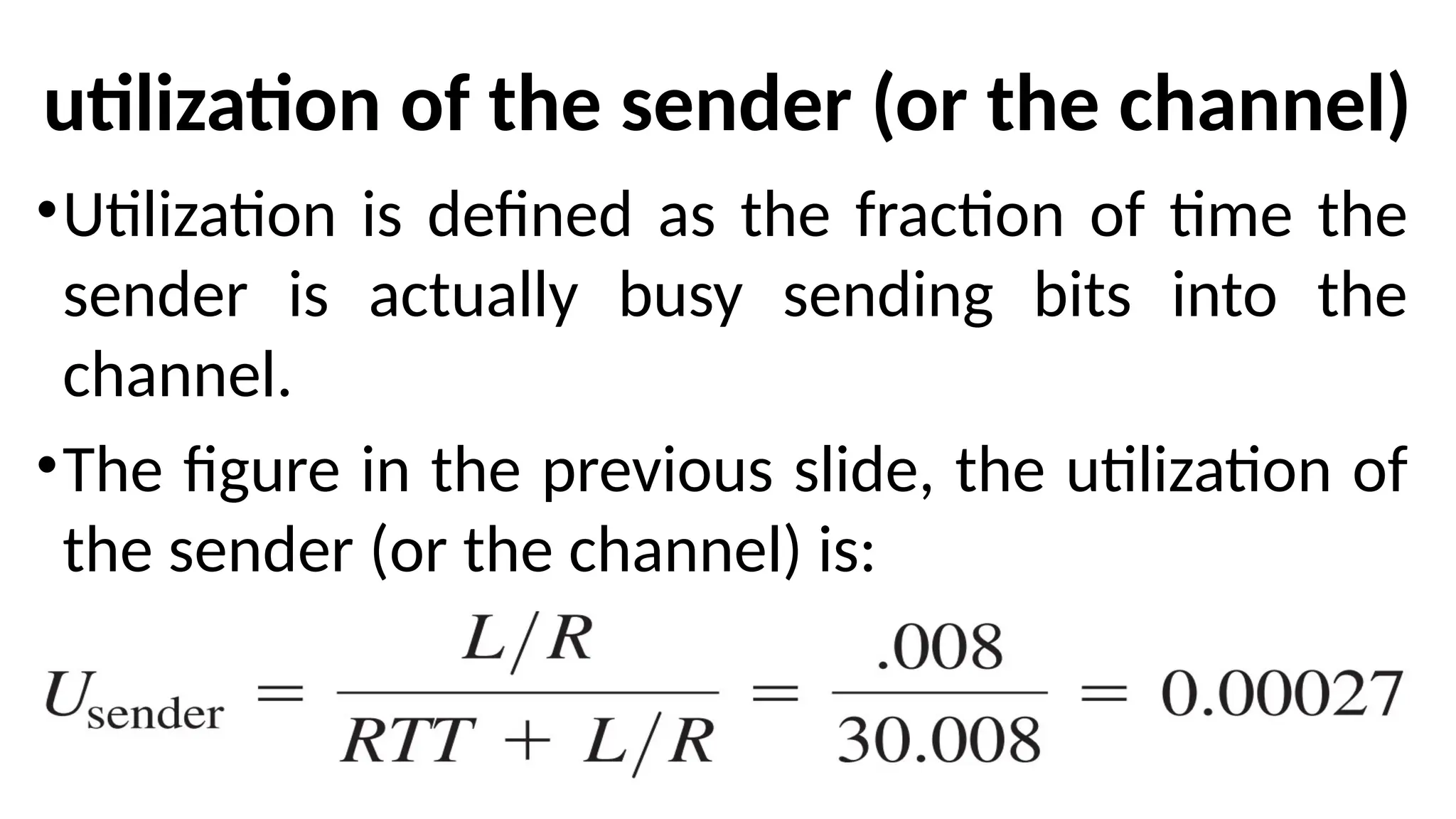
utilization of thesender (or the channel)
•Utilization is defined as the fraction of time the
sender is actually busy sending bits into the
channel.
•The figure in the previous slide, the utilization of
the sender (or the channel) is:
102.
•The sender wasable to send only 1,000 bytes
in 30.008 milliseconds.
•So an effective throughput of only 267 kbps
even though a 1 Gbps link was available.
103.
Disadvantage of Stopand Wait Protocol
•Lower-layer protocol-processing times at the
sender and receiver.
•The processing and queuing delays that would
occur at any intermediate routers between the
sender and receiver.
•These effects would serve only to further
increase the delay and further accentuate the
poor performance.
104.
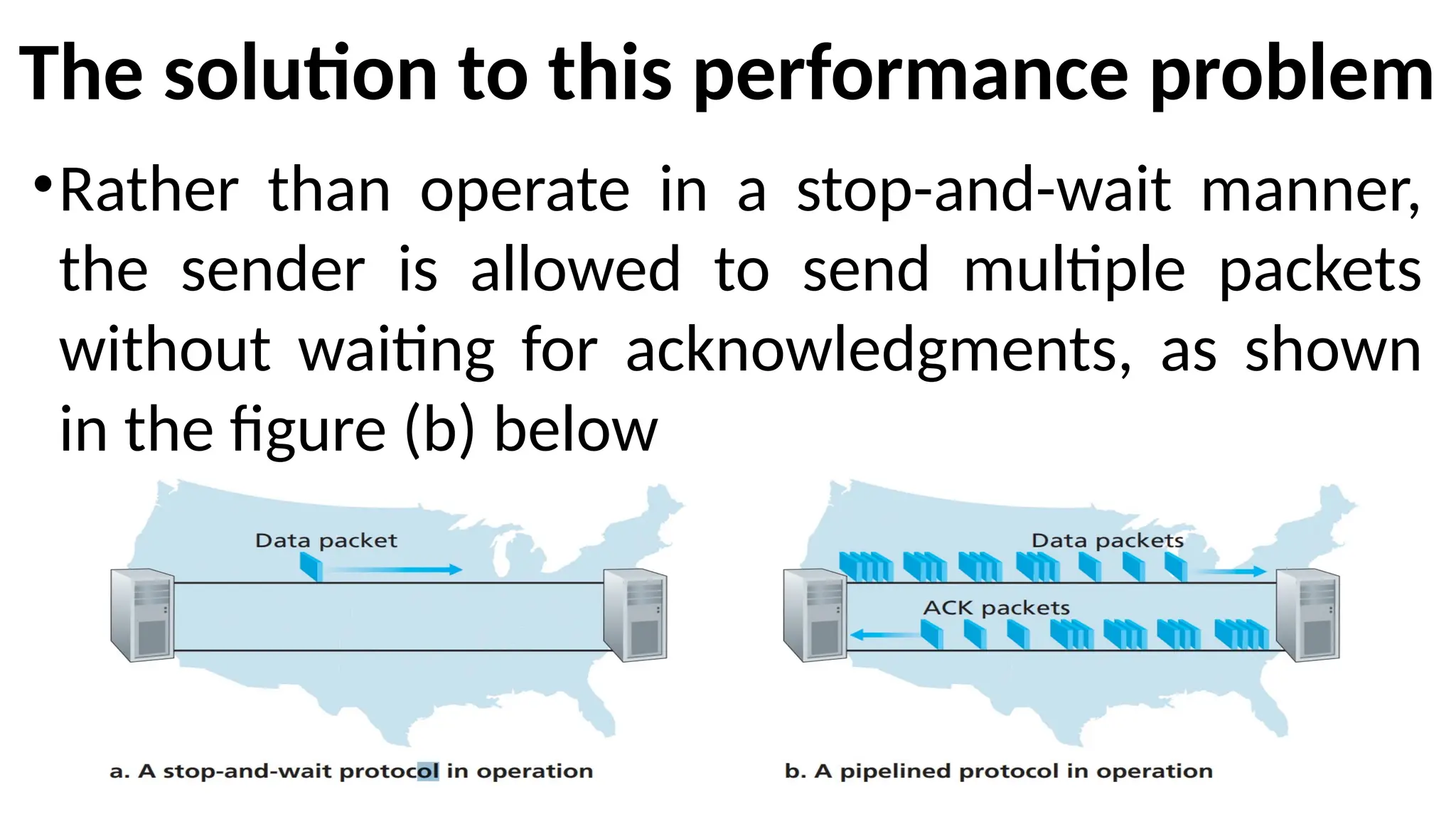
The solution tothis performance problem
•Rather than operate in a stop-and-wait manner,
the sender is allowed to send multiple packets
without waiting for acknowledgments, as shown
in the figure (b) below
105.
Consequences of Pipeliningfor
reliable data transfer protocols
• The range of sequence numbers must be increased, since each in-transit
packet (not counting retransmissions) must have a unique sequence number
and there may be multiple, in-transit, unacknowledged packets.
• The sender and receiver sides of the protocols may have to buffer more than
one packet. Minimally, the sender will have to buffer packets that have been
transmitted but not yet acknowledged. Buffering of correctly received packets
may also be needed at the receiver.
• The range of sequence numbers needed and the buffering requirements will
depend on the manner in which a data transfer protocol responds to lost,
corrupted, and overly delayed packets. Two basic approaches toward pipelined
error recovery can be identified: Go-Back-N and selective repeat.
106.
3.4 Principles ofReliable Data Transfer
Syllabus
•Building a Reliable Data Transfer Protocol.
• Pipelined Reliable Data Transfer Protocols.
• Go-Back-N.
•Selective repeat.
107.
3.4.3 Go-Back-N (GBN)
•Inthis protocol, the sender is allowed to
transmit multiple packet (when available)
without waiting for an acknowledgment, but is
constrained to have no more than some
maximum allowable number, N, of
unacknowledged packets in the pipeline.
108.
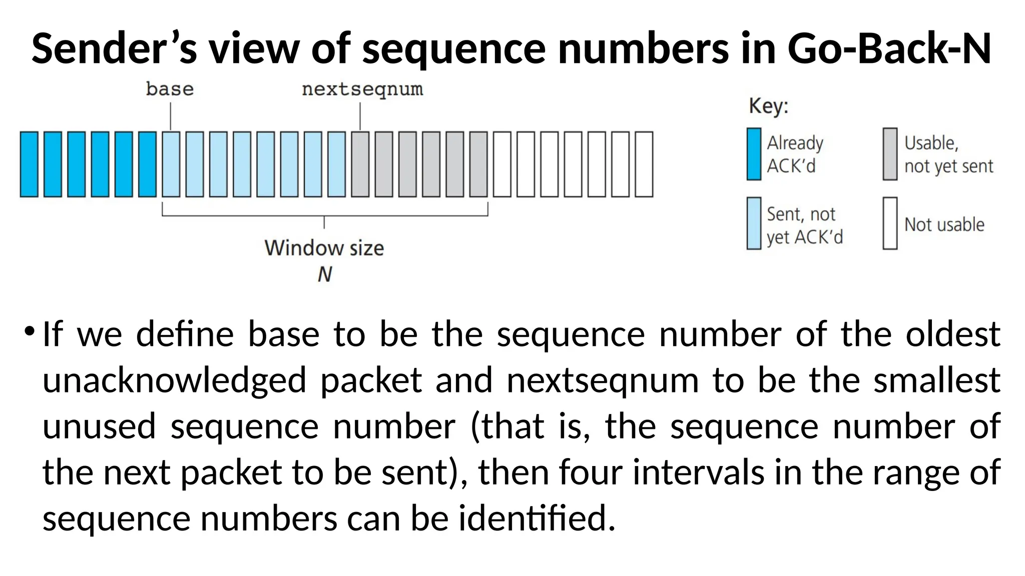
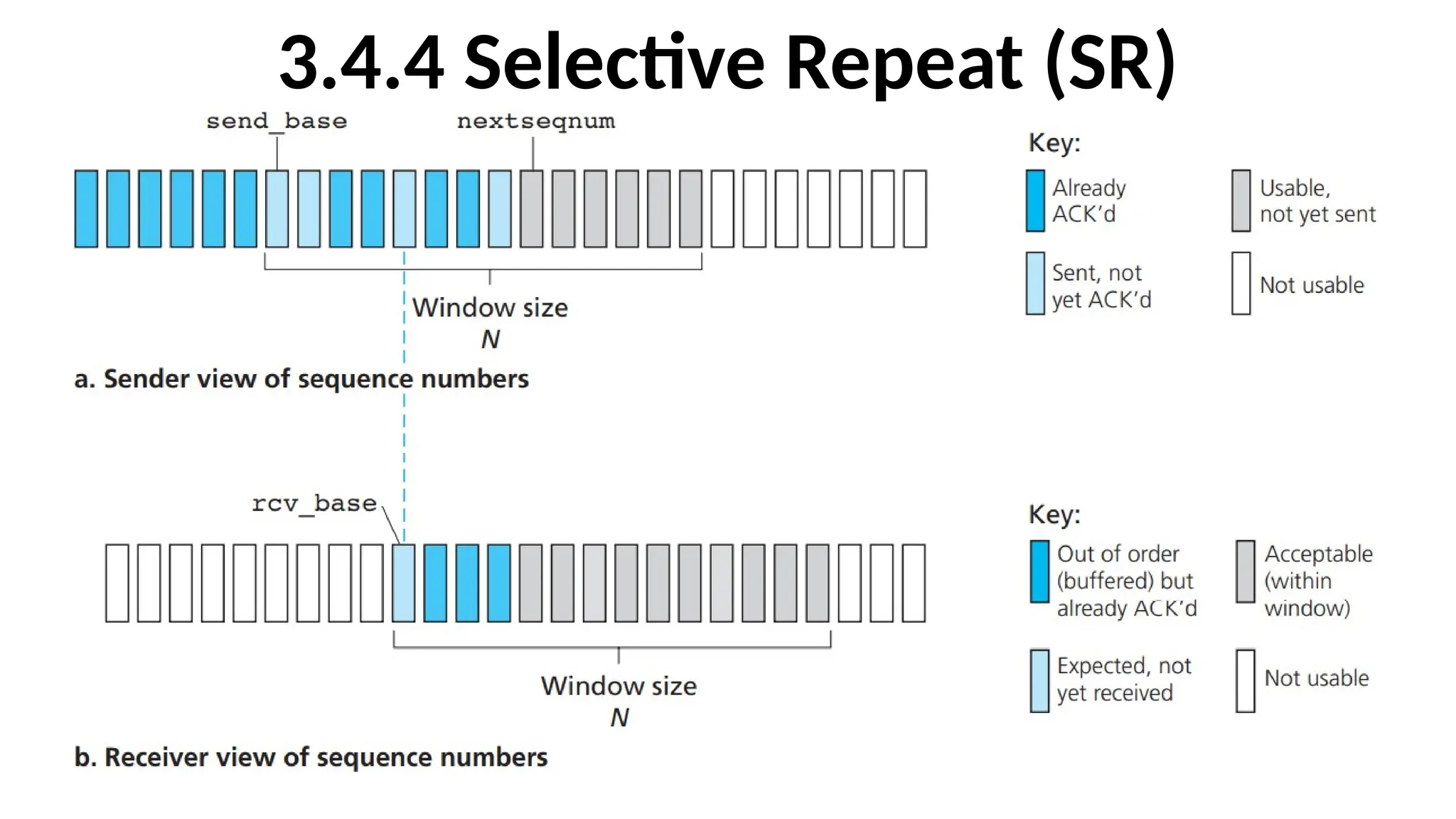
Sender’s view ofsequence numbers in Go-Back-N
• If we define base to be the sequence number of the oldest
unacknowledged packet and nextseqnum to be the smallest
unused sequence number (that is, the sequence number of
the next packet to be sent), then four intervals in the range of
sequence numbers can be identified.
109.
Four intervals inthe range of sequence numbers
• Sequence numbers in the interval [0, base-1] correspond to
packets that have already been transmitted and acknowledged.
• The interval [base, nextseqnum-1] corresponds to packets that
have been sent but not yet acknowledged.
• Sequence numbers in the interval [nextseqnum,base+N-1] can be
used for packets that can be sent immediately, should data arrive
from the upper layer.
• Sequence numbers greater than or equal to base+N cannot be
used until an unacknowledged packet currently in the pipeline
(specifically, the packet with sequence number base) has been
acknowledged.
110.
GBN is alsocalled as Sliding-Window Protocol
•The range of permissible sequence numbers for
transmitted but not yet acknowledged packets can
be viewed as a window of size N over the range of
sequence numbers. As the protocol operates, this
window slides forward over the sequence number
space. For this reason, N is often referred to as the
window size and the GBN protocol itself as a sliding-
window protocol.
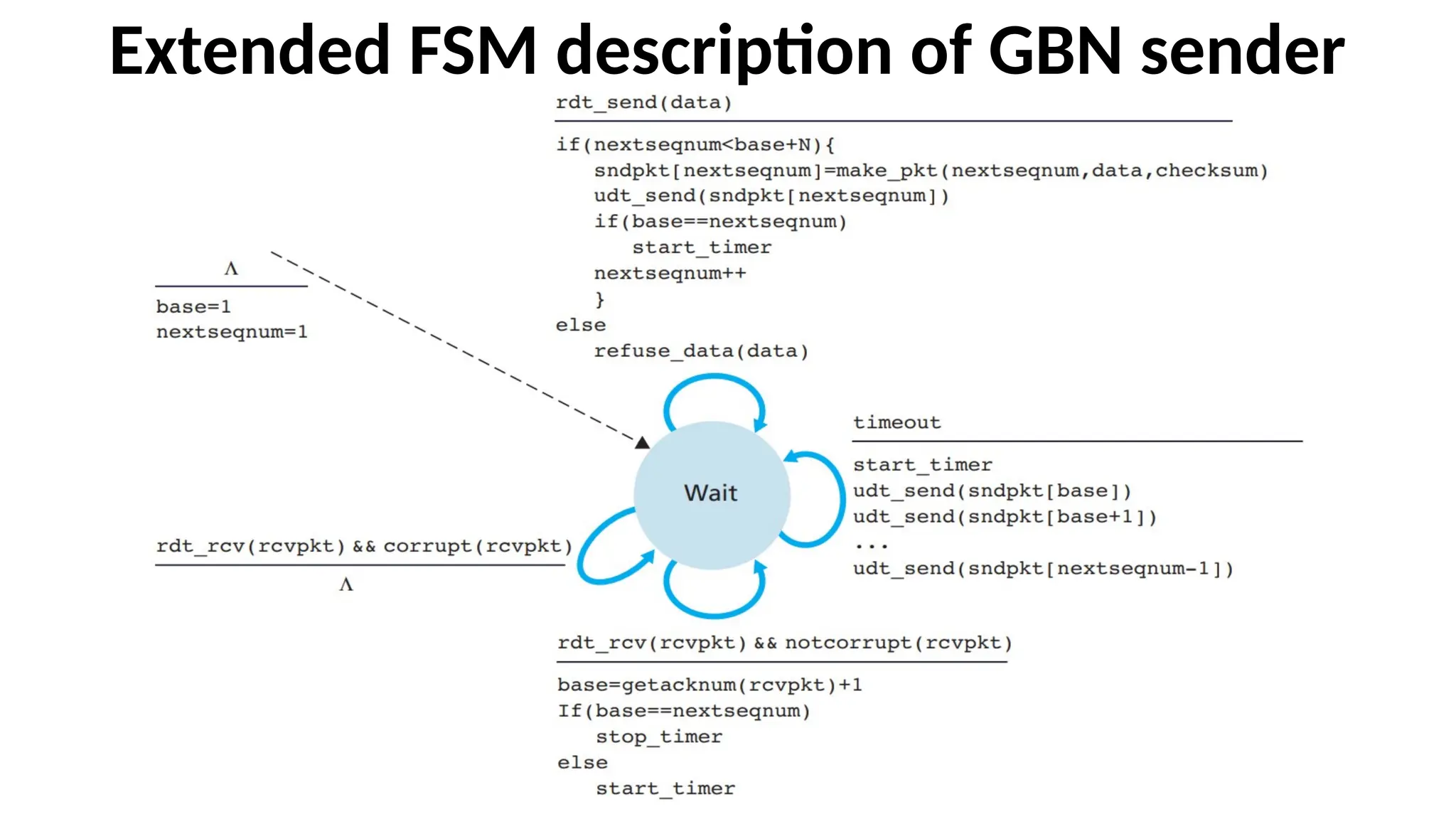
The GBN sendermust respond to three
types of events
•Invocation from above
•Receipt of an ACK
•A timeout event
114.
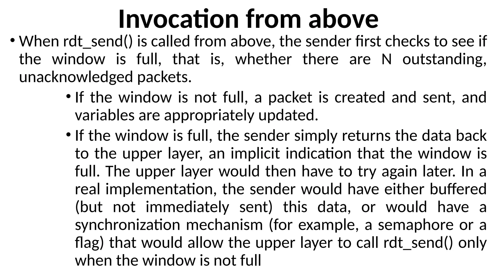
Invocation from above
•When rdt_send() is called from above, the sender first checks to see if
the window is full, that is, whether there are N outstanding,
unacknowledged packets.
• If the window is not full, a packet is created and sent, and
variables are appropriately updated.
• If the window is full, the sender simply returns the data back
to the upper layer, an implicit indication that the window is
full. The upper layer would then have to try again later. In a
real implementation, the sender would have either buffered
(but not immediately sent) this data, or would have a
synchronization mechanism (for example, a semaphore or a
flag) that would allow the upper layer to call rdt_send() only
when the window is not full
115.
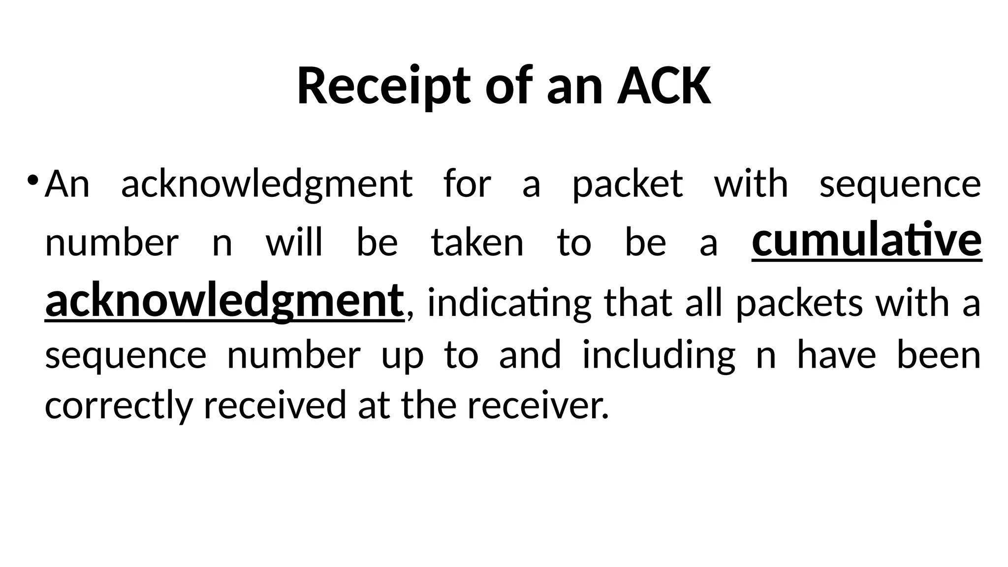
Receipt of anACK
•An acknowledgment for a packet with sequence
number n will be taken to be a cumulative
acknowledgment, indicating that all packets with a
sequence number up to and including n have been
correctly received at the receiver.
116.
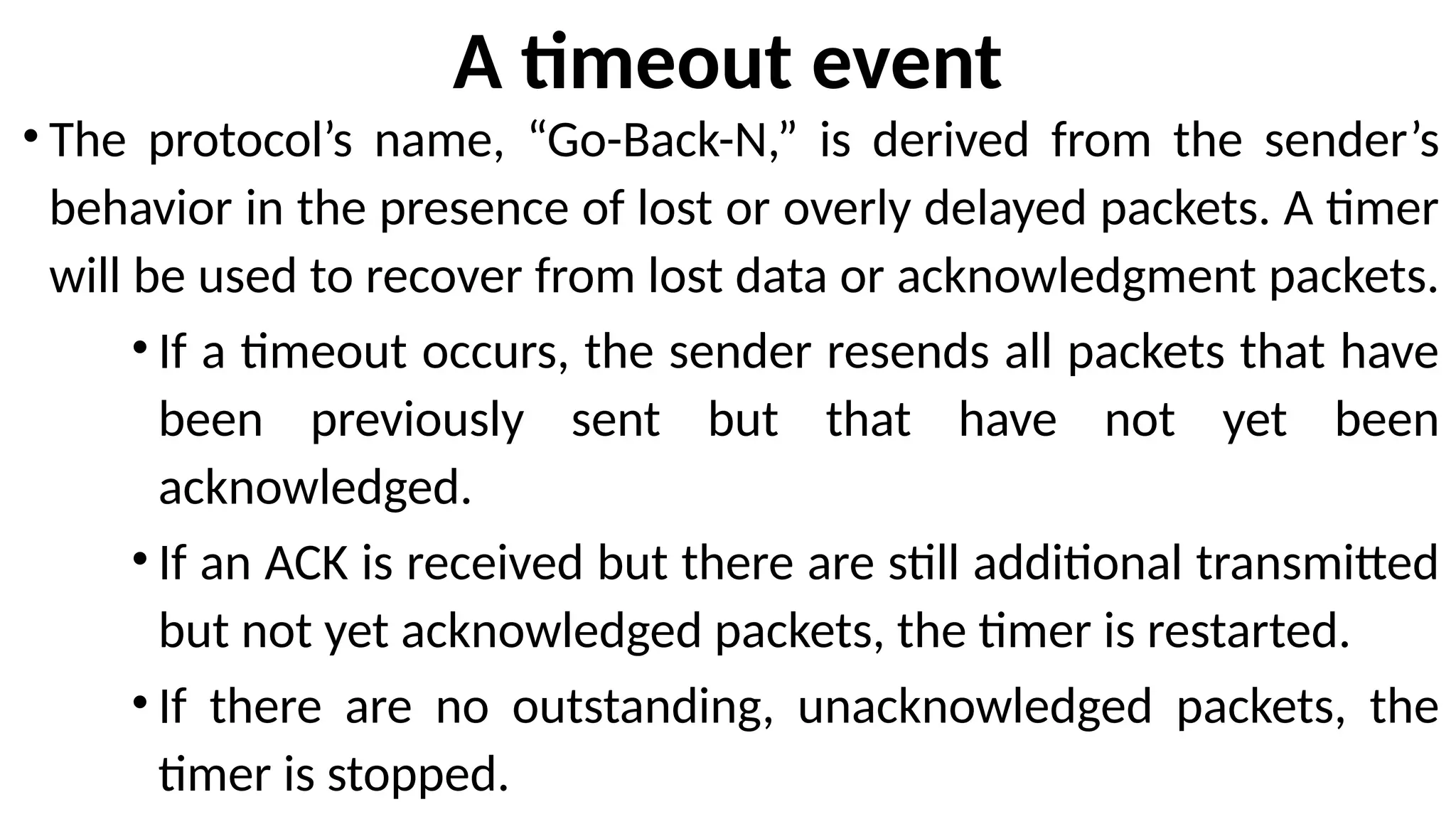
A timeout event
•The protocol’s name, “Go-Back-N,” is derived from the sender’s
behavior in the presence of lost or overly delayed packets. A timer
will be used to recover from lost data or acknowledgment packets.
• If a timeout occurs, the sender resends all packets that have
been previously sent but that have not yet been
acknowledged.
• If an ACK is received but there are still additional transmitted
but not yet acknowledged packets, the timer is restarted.
• If there are no outstanding, unacknowledged packets, the
timer is stopped.
117.
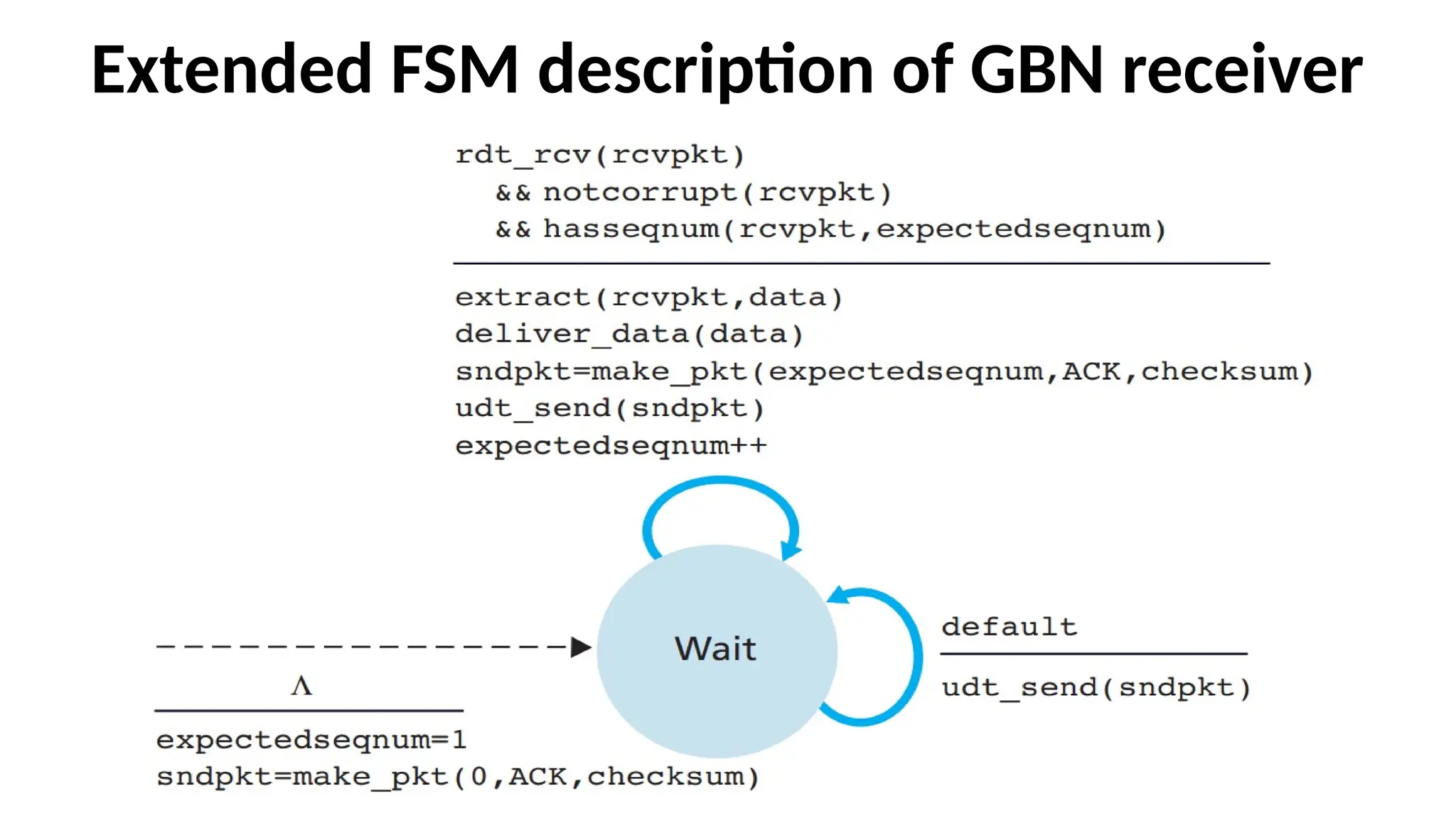
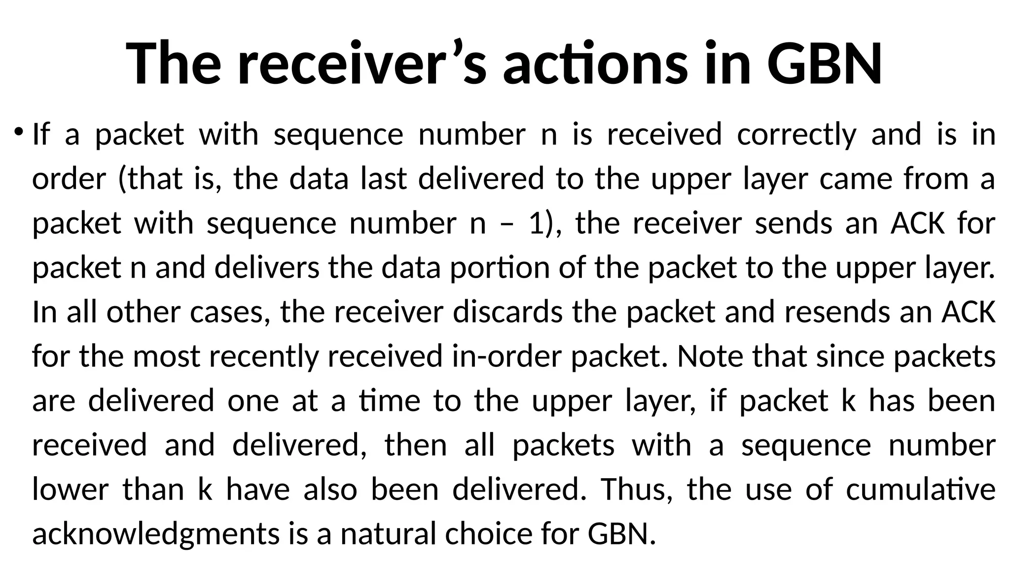
The receiver’s actionsin GBN
• If a packet with sequence number n is received correctly and is in
order (that is, the data last delivered to the upper layer came from a
packet with sequence number n – 1), the receiver sends an ACK for
packet n and delivers the data portion of the packet to the upper layer.
In all other cases, the receiver discards the packet and resends an ACK
for the most recently received in-order packet. Note that since packets
are delivered one at a time to the upper layer, if packet k has been
received and delivered, then all packets with a sequence number
lower than k have also been delivered. Thus, the use of cumulative
acknowledgments is a natural choice for GBN.
118.
The operation ofthe GBN protocol for the case of a window size of
four packets
119.
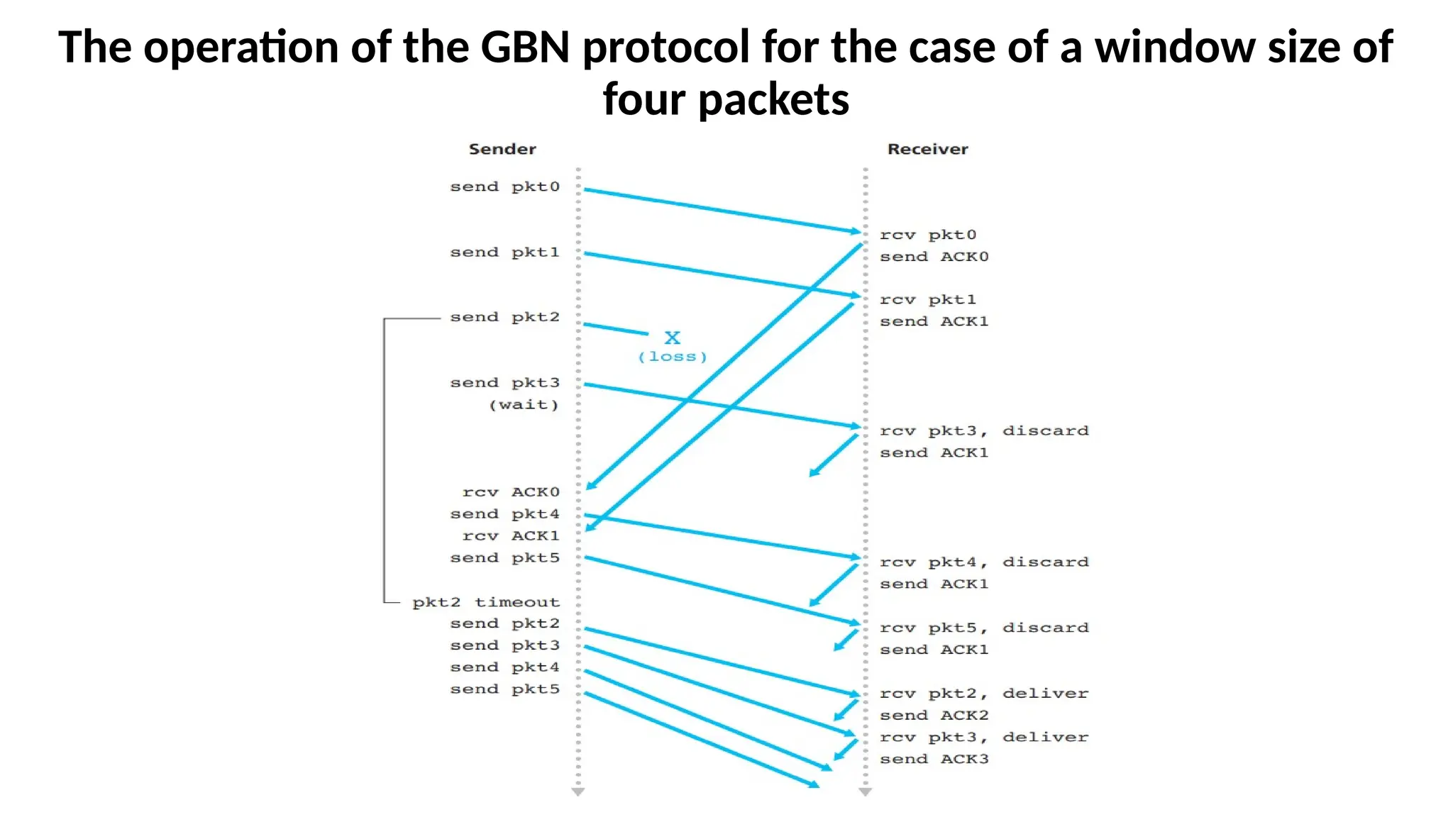
The operation ofthe GBN protocol for the
case of a window size of four packets
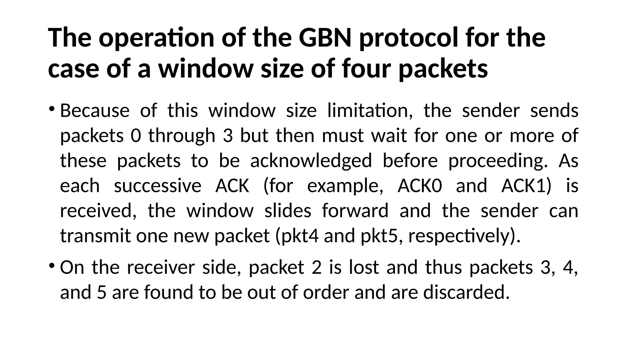
• Because of this window size limitation, the sender sends
packets 0 through 3 but then must wait for one or more of
these packets to be acknowledged before proceeding. As
each successive ACK (for example, ACK0 and ACK1) is
received, the window slides forward and the sender can
transmit one new packet (pkt4 and pkt5, respectively).
• On the receiver side, packet 2 is lost and thus packets 3, 4,
and 5 are found to be out of order and are discarded.
• Selective-Repeat Protocolsavoid unnecessary retransmissions
by having the sender retransmit only those packets that it
suspects were received in error (that is, were lost or corrupted)
at the receiver. This individual retransmission will require that
the receiver individually acknowledge correctly received
packets. A window size of N will again be used to limit the
number of outstanding, unacknowledged packets in the
pipeline. The sender will have already received ACKs for some of
the packets in the window.
122.
•The SR receiverwill acknowledge a correctly received
packet whether or not it is in order.
•Out-of-order packets are buffered until any missing
packets (that is, packets with lower sequence
numbers) are received, at which point a batch of
packets can be delivered in order to the upper layer.
123.
Various Actions takenby the SR sender
1. Data received from above.
2. Timeout.
3. ACK received.
124.
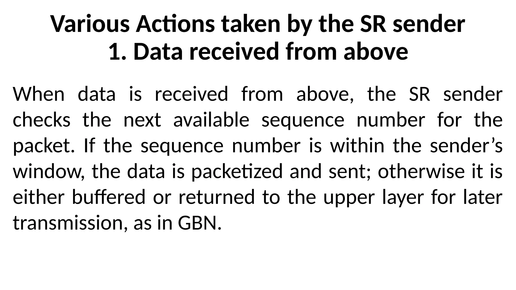
Various Actions takenby the SR sender
1. Data received from above
When data is received from above, the SR sender
checks the next available sequence number for the
packet. If the sequence number is within the sender’s
window, the data is packetized and sent; otherwise it is
either buffered or returned to the upper layer for later
transmission, as in GBN.
125.
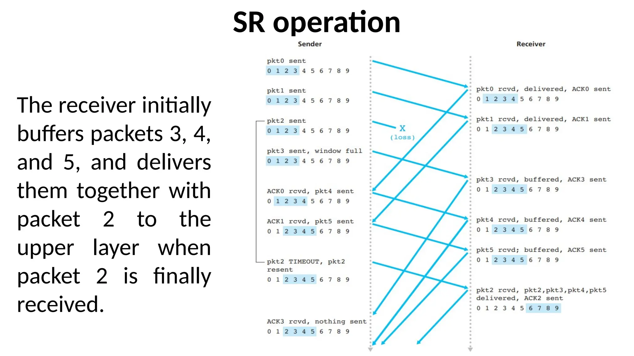
SR operation
The receiverinitially
buffers packets 3, 4,
and 5, and delivers
them together with
packet 2 to the
upper layer when
packet 2 is finally
received.
126.
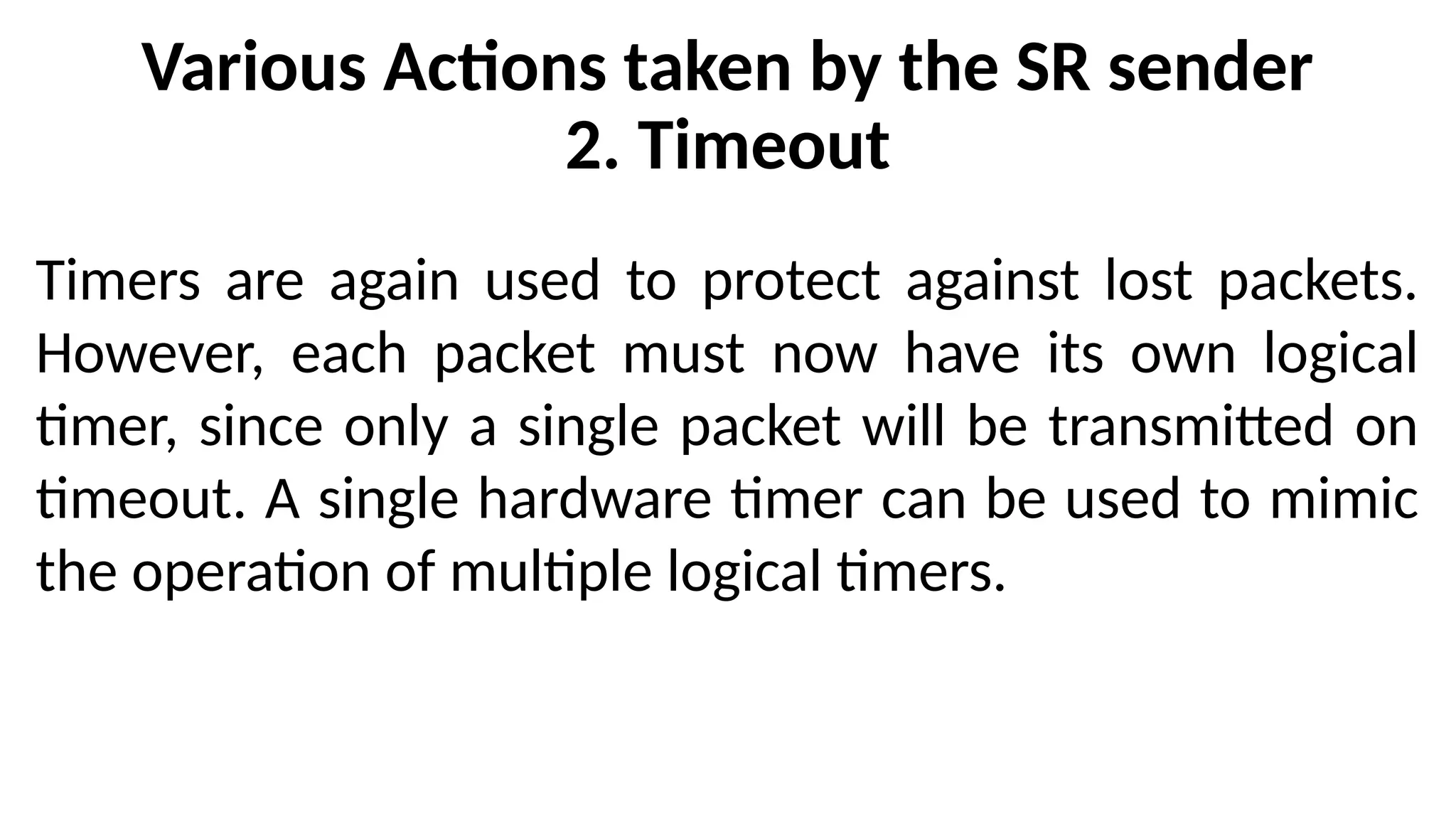
Various Actions takenby the SR sender
2. Timeout
Timers are again used to protect against lost packets.
However, each packet must now have its own logical
timer, since only a single packet will be transmitted on
timeout. A single hardware timer can be used to mimic
the operation of multiple logical timers.
127.
Various Actions takenby the SR sender
3. ACK received
If an ACK is received, the SR sender marks that packet as
having been received, provided it is in the window. If the
packet’s sequence number is equal to send_base, the window
base is moved forward to the unacknowledged packet with
the smallest sequence number. If the window moves and
there are untransmitted packets with sequence numbers that
now fall within the window, these packets are transmitted.
128.
SR receiver eventsand actions
1. Packet with sequence number in [rcv_base, rcv_base+N-1] is correctly
received. In this case, the received packet falls within the receiver’s window
and a selective ACK packet is returned to the sender. If the packet was not
previously received, it is buffered. If this packet has a sequence number equal
to the base of the receive window then this packet, and any previously
buffered and consecutively numbered (beginning with rcv_base) packets are
delivered to the upper layer. The receive window is then moved forward by
the number of packets delivered to the upper layer. When a packet with a
sequence number of rcv_base=2 is received, it and packets 3, 4, and 5 can be
delivered to the upper layer.
2. Packet with sequence number in [rcv_base-N, rcv_base-1] is correctly
received. In this case, an ACK must be generated, even though this is a packet
that the receiver has previously acknowledged.
3. Otherwise. Ignore the packet.
129.
Example
•Consider what couldhappen with a finite range of four
packet sequence numbers, 0, 1, 2, 3, and a window size of
three. Suppose packets 0 through 2 are transmitted and
correctly received and acknowledged at the receiver. At this
point, the receiver’s window is over the fourth, fifth, and
sixth packets, which have sequence numbers 3, 0, and 1,
respectively.
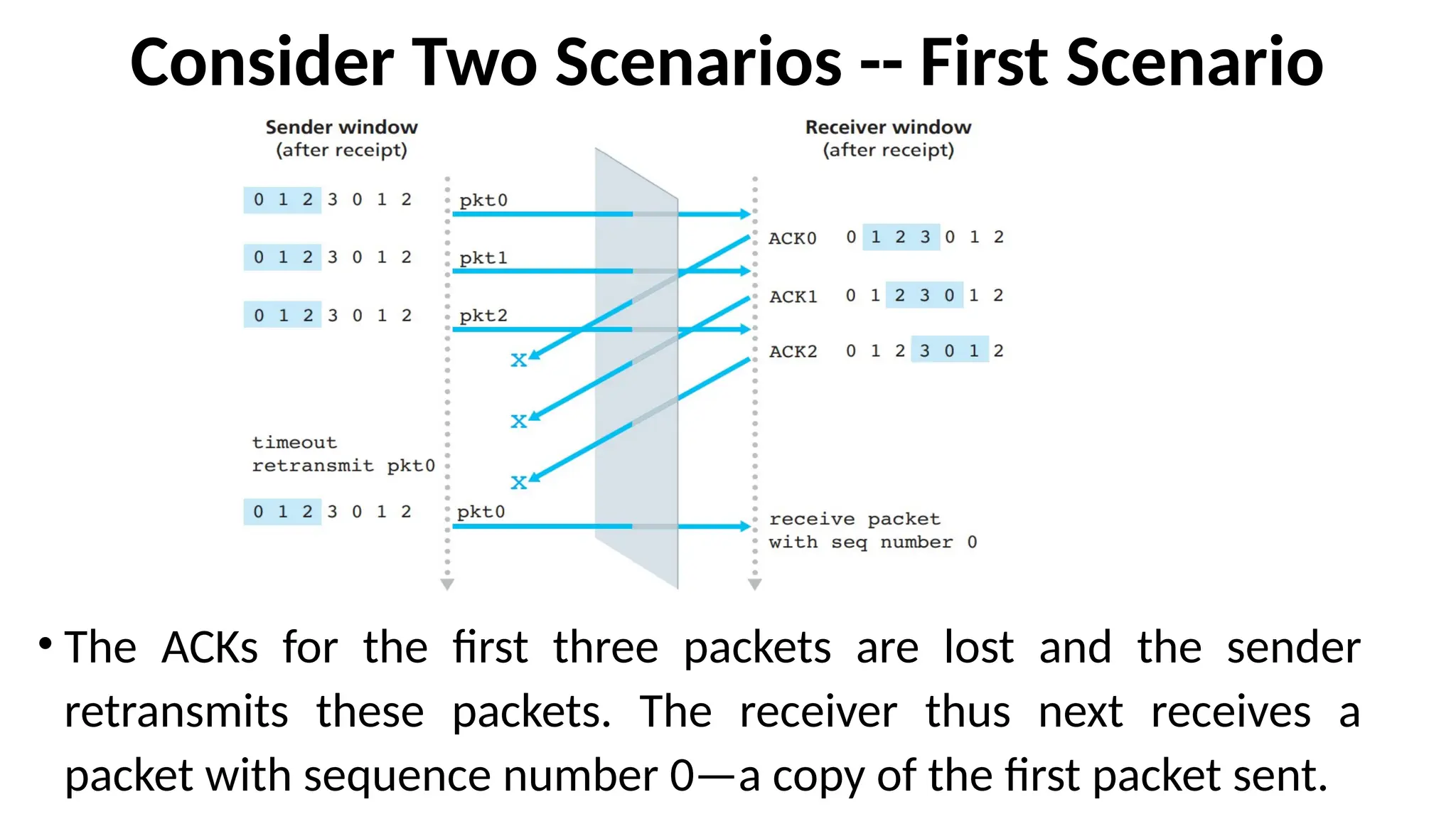
130.
Consider Two Scenarios-- First Scenario
• The ACKs for the first three packets are lost and the sender
retransmits these packets. The receiver thus next receives a
packet with sequence number 0—a copy of the first packet sent.
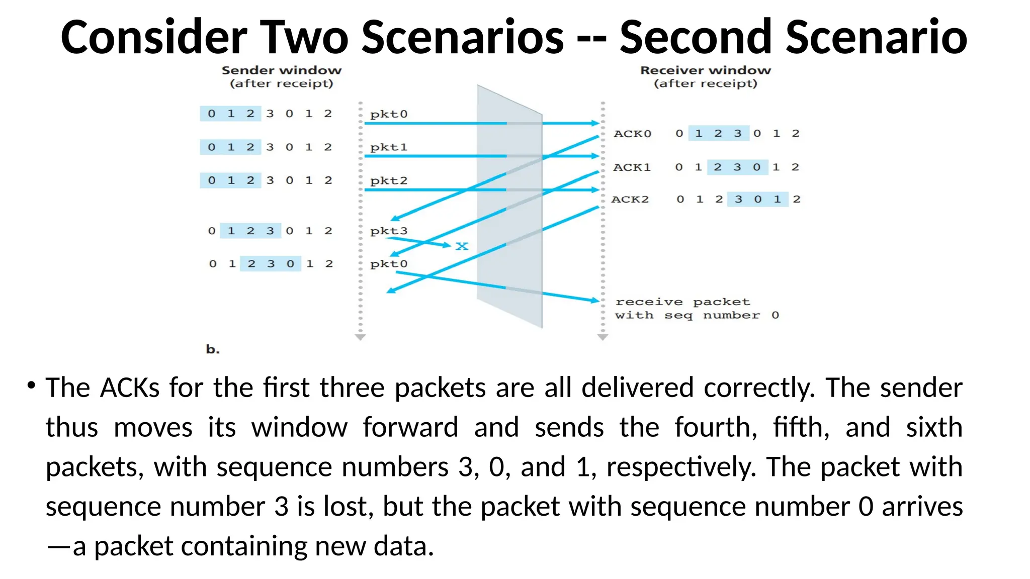
131.
Consider Two Scenarios-- Second Scenario
• The ACKs for the first three packets are all delivered correctly. The sender
thus moves its window forward and sends the fourth, fifth, and sixth
packets, with sequence numbers 3, 0, and 1, respectively. The packet with
sequence number 3 is lost, but the packet with sequence number 0 arrives
—a packet containing new data.
SYLLABUS – MODULE2
•Introduction and Transport-Layer Services: Relationship Between Transport
and Network Layers, Overview of the Transport Layer in the Internet,
•Multiplexing and Demultiplexing:
•Connectionless Transport -- UDP: UDP Segment Structure, UDP Checksum.
•Principles of Reliable Data Transfer: Building a Reliable Data Transfer Protocol,
Pipelined Reliable Data Transfer Protocols, Go-Back-N, Selective repeat.
•Connection-Oriented Transport TCP: The TCP Connection, TCP Segment
Structure, Round- Trip Time Estimation and Timeout, Reliable Data Transfer,
Flow Control, TCP Connection Management.
•Principles of Congestion Control: The Causes and the Costs of Congestion,
Approaches to Congestion Control, Network-assisted congestion-control
example, ATM ABR Congestion control.
•TCP Congestion Control: Fairness.
134.
3.5 Connection-Oriented Transport:TCP
Syllabus
•The TCP Connection,
•TCP Segment Structure,
•Round- Trip Time Estimation and Timeout,
•Reliable Data Transfer,
•Flow Control,
•TCP Connection Management.
135.
3.5.1 The TCPConnection
• TCP is said to be connection-oriented because before one
application process can begin to send data to another, the two
processes must first “handshake” with each other—that is, they
must send some preliminary segments to each other to establish the
parameters of the ensuing data transfer.
• As part of TCP connection establishment, both sides of the
connection will initialize many TCP state variables associated with
the TCP connection.
136.
A TCP connectionprovides a full-duplex service
•If there is a TCP connection between Process A on one host
and Process B on another host, then application layer data
can flow from Process A to Process B at the same time as
applicationlayer data flows from Process B to Process A.
137.
A TCP connectionis also always point-to-point
•A TCP connection is between a single sender and a
single receiver. So-called “multicasting”. The transfer
of data from one sender to many receivers in a single
send operation—is not possible with TCP. With TCP,
two hosts are company and three are a crowd
138.
How a TCPconnection is established?
• Suppose a process running in one host wants to initiate a connection
with another process in another host.
• The process that is initiating the connection is called the client
process. The other process is called the server process.
• The client application process first informs the client transport layer
that it wants to establish a connection to a process in the server.
• a Python client program does this by issuing the command
clientSocket.connect((serverName, serverPort))
where serverName is the name of the server and serverPort
identifies the process on the server
• TCP in the client then proceeds to establish a TCP connection with
TCP in the server.
139.
Three-Way Handshake
•The clientfirst sends a special TCP segment.
•The server responds with a second special TCP segment.
•Finally the client responds again with a third special segment.
•The first two segments carry no payload, that is, no
application-layer data; the third of these segments may carry
a payload.
•Because three segments are sent between the two hosts, this
connection-establishment procedure is often referred to as a
three-way handshake
140.
• Once aTCP connection is established, the two application processes
can send data to each other.
• Let’s consider the sending of data from the client process to the
server process. The client process passes a stream of data through
the socket.
• TCP directs this data to the connection’s send buffer, which is one of
the buffers that is set aside during the initial three-way handshake.
• TCP will grab chunks of data from the send buffer and pass the data
to the network layer.
141.
Maximum Segment Size(MSS)
• The maximum amount of data that can be grabbed and
placed in a segment is limited by the Maximum Segment Size
(MSS).
• The MSS is typically set by first determining the length of the
largest link-layer frame that can be sent by the local sending
host (the so-called Maximum Transmission Unit, MTU), and
then setting the MSS to ensure that a TCP segment plus the
TCP/IP header length (typically 40 bytes) will fit into a single
link-layer frame.
142.
•TCP pairs eachchunk of client data with a TCP header, thereby
forming TCP segments. The segments are passed down to the
network layer, where they are separately encapsulated within
network-layer IP datagrams. The IP datagrams are then sent
into the network.
•When TCP receives a segment at the other end, the segment’s
data is placed in the TCP connection’s receive buffer.
•The application reads the stream of data from this buffer.
•Each side of the connection has its own send buffer and its
own receive buffer.
143.
•A TCP connectionconsists of buffers, variables, and a
socket connection to a process in one host, and
another set of buffers, variables, and a socket
connection to a process in another host.
•No buffers or variables are allocated to the connection
in the network elements (routers, switches, and
repeaters) between the hosts.
144.
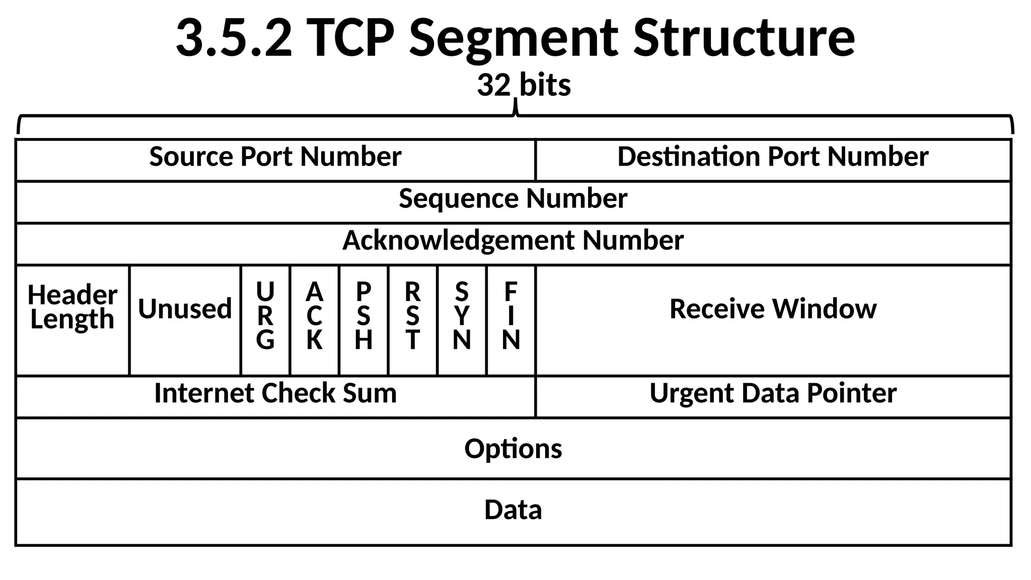
3.5.2 TCP SegmentStructure
•The TCP segment consists of header fields and a data field.
•The data field contains a chunk of application data.
•The MSS limits the maximum size of a segment’s data field.
•When TCP sends a large file, such as an image as part
of a Web page, it breaks the file into chunks of size
MSS (except for the last chunk, which will often be
less than the MSS).
•Interactive applications, transmit data chunks that
are smaller than the MSS.
145.
3.5.2 TCP SegmentStructure
Source Port Number Destination Port Number
Sequence Number
Acknowledgement Number
Header
Length Unused
U
R
G
A
C
K
P
S
H
R
S
T
S
Y
N
F
I
N
Receive Window
Internet Check Sum Urgent Data Pointer
Options
Data
32 bits
146.
•The header includes
•SourcePort Number and
•Destination Port Number
•These are used for multiplexing/demultiplexing data
from/to upper-layer applications.
•The header includes a checksum field.
147.
A TCP segmentheader also contains the
following fields
•The 32-bit sequence number field and the 32-bit
acknowledgment number field are used by the TCP
sender and receiver in implementing a reliable data
transfer service.
•The 16-bit receive window field is used for flow
control. It is used to indicate the number of bytes that
a receiver is willing to accept.
148.
A TCP segmentheader also contains the
following fields
•The 4-bit header length field specifies the length of the
TCP header in 32-bit words. The TCP header can be of
variable length due to the TCP options field.
(Normally, the options field is empty, so that the length
of the typical TCP header is 20 bytes.)
•The optional and variable-length options field is used
when a sender and receiver negotiate the maximum
segment size (MSS) or as a window scaling factor for
use in high-speed networks
Contd…
149.
A TCP segmentheader also contains the
following fields
• The Flag Field contains 6 bits.
• The ACK bit is used to indicate that the value carried in the
acknowledgment field is valid; that is, the segment contains an
acknowledgment for a segment that has been successfully
received.
• The RST, SYN, and FIN bits are used for connection setup and
teardown.
• Setting the PSH bit indicates that the receiver should pass the
data to the upper layer immediately.
• Finally, the URG bit is used to indicate that there is data in this
segment that the sending-side upper-layer entity has marked as
“urgent.”
Contd…
150.
A TCP segmentheader also contains the
following fields
•The location of the last byte of this urgent data is
indicated by the 16-bit urgent data pointer field.
•TCP must inform the receiving-side upper-layer entity
when urgent data exists and pass it a pointer to the
end of the urgent data.
Contd…
151.
Sequence Numbers and
AcknowledgmentNumbers
• These fields are a critical part of TCP’s reliable data transfer
service.
• TCP views data as an unstructured, but ordered, stream of
bytes.
• TCP’s use of sequence numbers reflects this view in that
sequence numbers are over the stream of transmitted bytes
and not over the series of transmitted segments.
• The sequence number for a segment is therefore the byte-
stream number of the first byte in the segment.
152.
Example
•Suppose that aprocess in Host A wants to send a stream
of data to a process in Host B over a TCP connection. The
TCP in Host A will implicitly number each byte in the data
stream.
•Suppose that the data stream consists of a file consisting
of 500,000 bytes, that the MSS is 1,000 bytes, and that the
first byte of the data stream is numbered 0.
153.
Example
• Suppose thata process in Host A wants to send a stream of data to a
process in Host B over a TCP connection. The TCP in Host A will
implicitly number each byte in the data stream.
• Suppose that the data stream consists of a file consisting of 500,000
bytes, that the MSS is 1,000 bytes, and that the first byte of the data
stream is numbered 0.
• TCP constructs 500 segments out of the data stream. The first
segment gets assigned sequence number 0, the second segment gets
assigned sequence number 1,000, the third segment gets assigned
sequence number 2,000, and so on. Each sequence number is
inserted in the sequence number field in the header of the
appropriate TCP segment.
154.
• Now, let’sconsider acknowledgment numbers.
• TCP is full-duplex, so that Host A may be receiving data from Host B while it
sends data to Host B (as part of the same TCP connection).
• Each of the segments that arrive from Host B has a sequence number for the
data.


![Four intervals in the range of sequence numbers
• Sequence numbers in the interval [0, base-1] correspond to
packets that have already been transmitted and acknowledged.
• The interval [base, nextseqnum-1] corresponds to packets that
have been sent but not yet acknowledged.
• Sequence numbers in the interval [nextseqnum,base+N-1] can be
used for packets that can be sent immediately, should data arrive
from the upper layer.
• Sequence numbers greater than or equal to base+N cannot be
used until an unacknowledged packet currently in the pipeline
(specifically, the packet with sequence number base) has been
acknowledged.](https://image.slidesharecdn.com/cnsmodule2ppt-250412153943-17d01e25/75/VTU-V-SEM-CNS-Module-1-PPT-2018-Batch-students-109-2048.jpg)
![SR receiver events and actions
1. Packet with sequence number in [rcv_base, rcv_base+N-1] is correctly
received. In this case, the received packet falls within the receiver’s window
and a selective ACK packet is returned to the sender. If the packet was not
previously received, it is buffered. If this packet has a sequence number equal
to the base of the receive window then this packet, and any previously
buffered and consecutively numbered (beginning with rcv_base) packets are
delivered to the upper layer. The receive window is then moved forward by
the number of packets delivered to the upper layer. When a packet with a
sequence number of rcv_base=2 is received, it and packets 3, 4, and 5 can be
delivered to the upper layer.
2. Packet with sequence number in [rcv_base-N, rcv_base-1] is correctly
received. In this case, an ACK must be generated, even though this is a packet
that the receiver has previously acknowledged.
3. Otherwise. Ignore the packet.](https://image.slidesharecdn.com/cnsmodule2ppt-250412153943-17d01e25/75/VTU-V-SEM-CNS-Module-1-PPT-2018-Batch-students-128-2048.jpg)