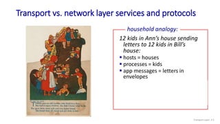
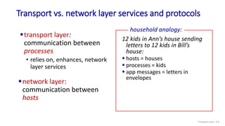
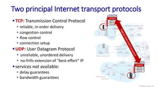
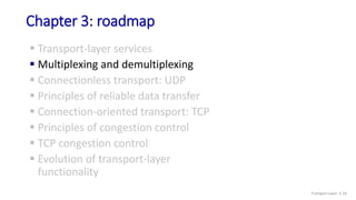
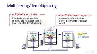
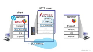
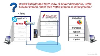
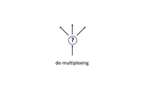
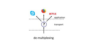
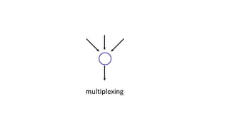
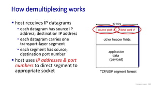
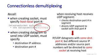
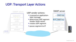
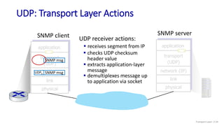
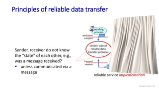
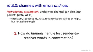
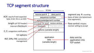
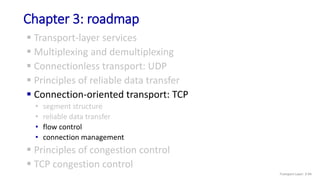
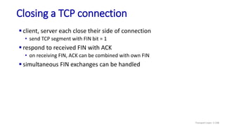
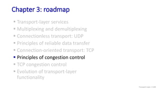
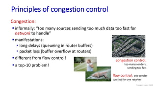
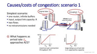
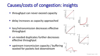
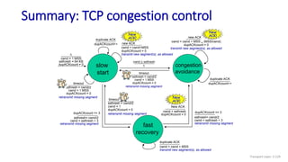
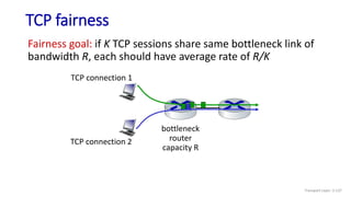
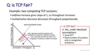
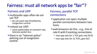
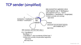
The document discusses the transport layer and provides an overview of key concepts. It introduces transport layer services including multiplexing, demultiplexing, and reliable data transfer. It describes the two main Internet transport protocols - UDP which provides connectionless unreliable data transfer, and TCP which provides connection-oriented reliable transfer. The document outlines the concepts that will be covered in more detail, including multiplexing, demultiplexing, the transport protocols UDP and TCP, and congestion control.

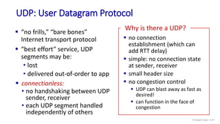
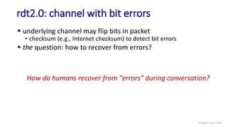
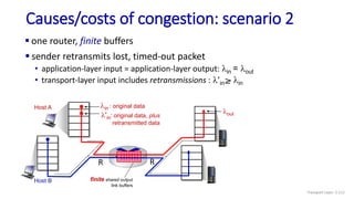
![UDP: User Datagram Protocol [RFC 768]
Transport Layer: 3-31](https://image.slidesharecdn.com/cnmodule3ppt-240324100557-c897a0f4/85/Computer-networks-Module-3-Transport-layer-31-320.jpg)
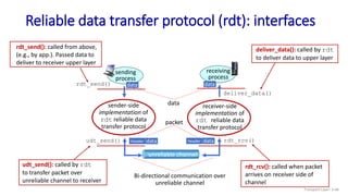
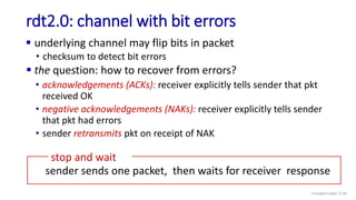

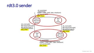
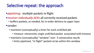
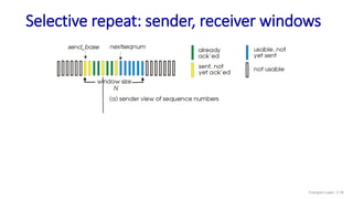
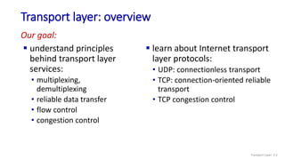
![Selective repeat: sender and receiver
data from above:
if next available seq # in
window, send packet
timeout(n):
resend packet n, restart timer
ACK(n) in [sendbase,sendbase+N-1]:
mark packet n as received
if n smallest unACKed packet,
advance window base to next
unACKed seq #
sender
packet n in [rcvbase, rcvbase+N-1]
send ACK(n)
out-of-order: buffer
in-order: deliver (also deliver
buffered, in-order packets),
advance window to next not-yet-
received packet
packet n in [rcvbase-N,rcvbase-1]
ACK(n)
otherwise:
ignore
receiver
Transport Layer: 3-77](https://image.slidesharecdn.com/cnmodule3ppt-240324100557-c897a0f4/85/Computer-networks-Module-3-Transport-layer-77-320.jpg)
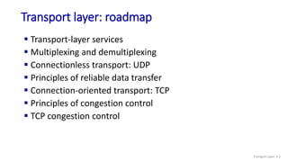
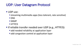
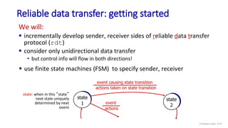
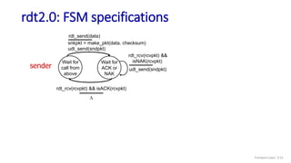
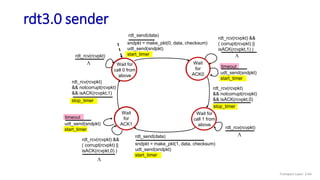
![TCP Receiver: ACK generation [RFC 5681]
Event at receiver
arrival of in-order segment with
expected seq #. All data up to
expected seq # already ACKed
arrival of in-order segment with
expected seq #. One other
segment has ACK pending
arrival of out-of-order segment
higher-than-expect seq. # .
Gap detected
arrival of segment that
partially or completely fills gap
TCP receiver action
delayed ACK. Wait up to 500ms
for next segment. If no next segment,
send ACK
immediately send single cumulative
ACK, ACKing both in-order segments
immediately send duplicate ACK,
indicating seq. # of next expected byte
immediate send ACK, provided that
segment starts at lower end of gap
Transport Layer: 3-90](https://image.slidesharecdn.com/cnmodule3ppt-240324100557-c897a0f4/85/Computer-networks-Module-3-Transport-layer-90-320.jpg)

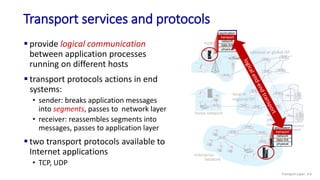
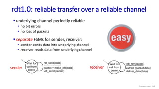
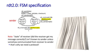
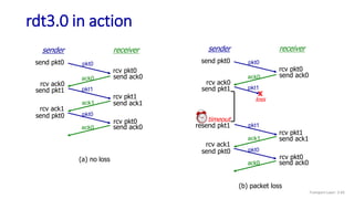
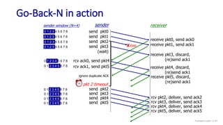
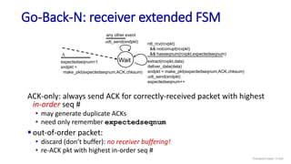
![Go-Back-N: sender extended FSM
Transport Layer: 3-141
Wait
start_timer
udt_send(sndpkt[base])
udt_send(sndpkt[base+1])
…
udt_send(sndpkt[nextseqnum-1])
timeout
rdt_send(data)
if (nextseqnum < base+N) {
sndpkt[nextseqnum] = make_pkt(nextseqnum,data,chksum)
udt_send(sndpkt[nextseqnum])
if (base == nextseqnum)
start_timer
nextseqnum++
}
else
refuse_data(data)
base = getacknum(rcvpkt)+1
If (base == nextseqnum)
stop_timer
else
start_timer
rdt_rcv(rcvpkt) &&
notcorrupt(rcvpkt)
base=1
nextseqnum=1
rdt_rcv(rcvpkt)
&& corrupt(rcvpkt)
L](https://image.slidesharecdn.com/cnmodule3ppt-240324100557-c897a0f4/85/Computer-networks-Module-3-Transport-layer-141-320.jpg)
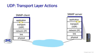
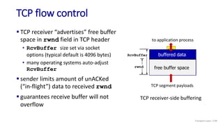
![TCP over “long, fat pipes”
Transport Layer: 3-147
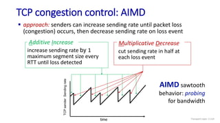
example: 1500 byte segments, 100ms RTT, want 10 Gbps throughput
requires W = 83,333 in-flight segments
throughput in terms of segment loss probability, L [Mathis 1997]:
➜ to achieve 10 Gbps throughput, need a loss rate of L = 2·10-10 – a
very small loss rate!
versions of TCP for long, high-speed scenarios
TCP throughput =
1.22 . MSS
RTT L](https://image.slidesharecdn.com/cnmodule3ppt-240324100557-c897a0f4/85/Computer-networks-Module-3-Transport-layer-147-320.jpg)


