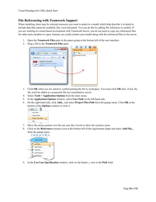
Downloaded 141 times

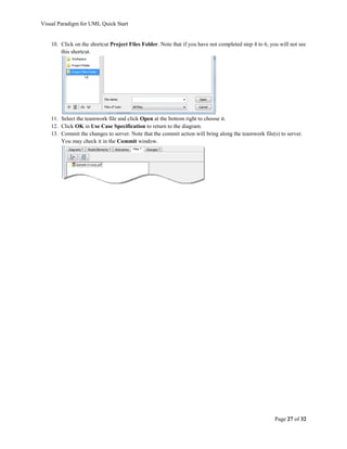
![Visual Paradigm for UML Quick Start
UML Modeling
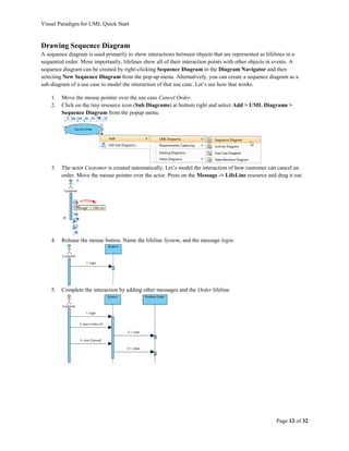
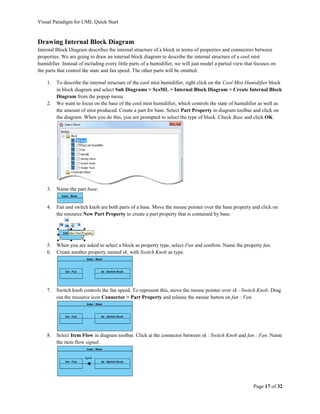
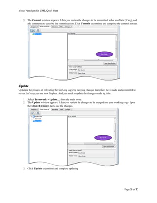
Drawing Use Case Diagrams
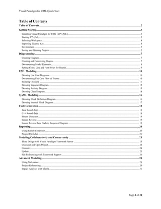
A use case diagram is used to model and identify the functional requirements of a software system. In a use case
diagram, all stakeholders and system goals are identified to elaborate how the system is formed. The main elements
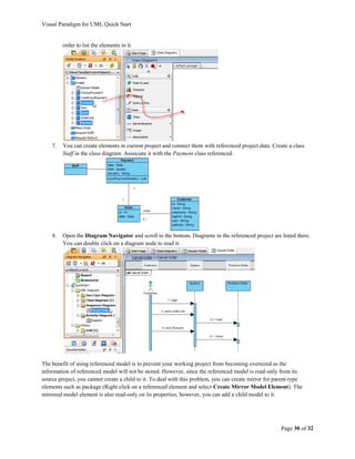
of a use case diagram include actor, use case and association (communication link).
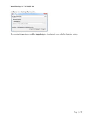
An actor is any person or external system that interacts with the system to achieve a user goal (i.e. use case). The
following simple use case diagram illustrates the use cases of a sales order system. Customer, an actor, interacts with
the system to accomplish the goal of order placement, as modeled by the use case Place Order. There are other
goals that the customer wants to accomplish, such as Request Refund and Cancel Order.
Now, apply the diagramming techniques described in the previous section to draw the diagram. You can drag the
resize handler surrounding a shape to resize it. To reshape a connector, press on it and drag around to produce and
move a pivot point (which appears as a bubble).
Documenting Use Case Flow of Events [Professional Edition or above]
A use case’s name tells us the 'what' aspect of a use case – what the users need. Meanwhile, the flow of events
shows the 'how' aspect of a use case by explaining how a user’s goal can be achieved. It is a technique for analyzing
interaction between the actor and the system in accomplishing a use case. To work with the flow of events editor:
1. Right-click on a use case (e.g. Place Order) and select Open Use Case Details… from the popup menu.
2. Open the Flow of Events tab.
3. Enter the steps involved in accomplishing the Place Order use case.
Tips:
- Create a new step by pressing Enter.
- Set a step as sub-step by pressing Tab.
- Add and declare a step responded by the system
by clicking and selecting System Response
from the popup menu.
- Make use of the formatting functions (e.g. bold,
italic, etc) to format text.
4. At the bottom of the editor you can find the Extension section. An extension represents a variation of the
use case being extended. The variation may be triggered when walking through the main flow, under
certain conditions. Let’s assume the place order use case is capable in handling rush order. Right click on
step 5 where a user proceeds with buying. Select Add Extension from the popup menu.
Page 10 of 32](https://image.slidesharecdn.com/quickstartvpuml-120701145728-phpapp02/85/visual-paradigm-uml-10-320.jpg)
![Visual Paradigm for UML Quick Start
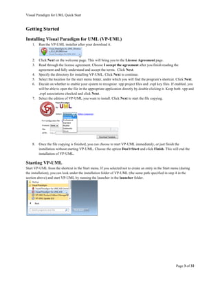
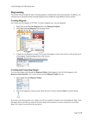
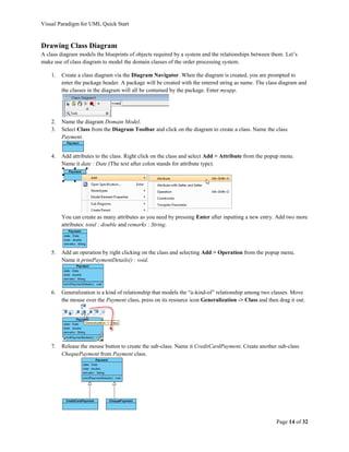
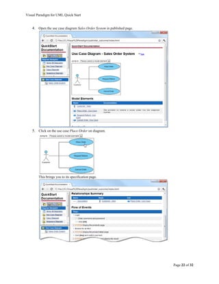
5. Fill in the steps required for handling rush order.
Building Glossary [Modeler Edition or above]
A glossary is a place where domain-specific vocabularies are stored and managed. And you can build a glossary by
identifying terms in a flow of events.
1. Suppose rush order is a key phrase that requires definition. Highlight it in the flow of events, right-click to
select Add “rush order” to Glossary from the pop-up menu to make it a term.
2. This opens a glossary with the term online system homepage added. Right-click on the term to select Open
Term Editor from the pop-up menu.
3. Specify its alias. In the Term Editor, click Add and enter urgent order. Add also quick order as alias.
Enter the term’s definition in the Definition section below.
Note Move your mouse pointer to the underlined term online system homepage in the Flow of Events,
the documentation of the term will appear automatically.
Page 11 of 32](https://image.slidesharecdn.com/quickstartvpuml-120701145728-phpapp02/85/visual-paradigm-uml-11-320.jpg)
![Visual Paradigm for UML Quick Start
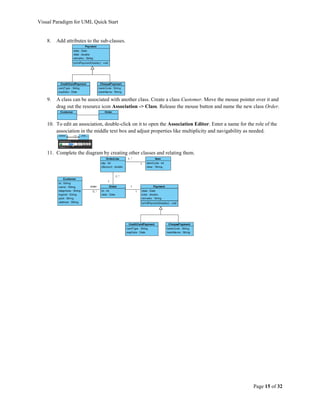
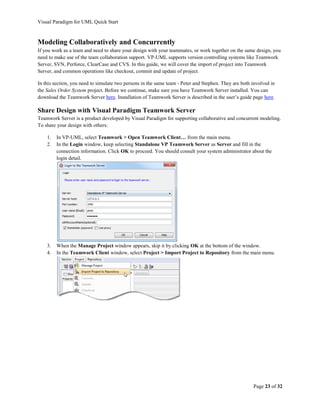
Drawing Activity Diagram
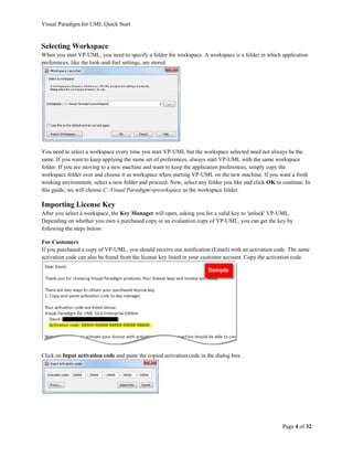
An activity diagram is essentially a flowchart, showing flow of control from one activity to another. Unlike a
traditional flowchart, it can model the dynamic aspects of a system because it involves modeling the sequential steps
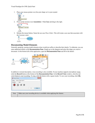
in a computational process. Let’s make use of activity diagram to model the registration process.
1. Create an activity diagram via the Diagram Navigator. Name the diagram Register.
2. Select Initial Node from the Diagram Toolbar. Click on the diagram to create an initial node, which
represents the beginning of a flow.
3. Press on the initial node’s resource icon Control Flow -> Action and drag it. Release the mouse button to
create an action and name it Click [Register]. This is the first action of the flow.
4. Complete the rest of the flow as shown below. The diamond shape is a decision node which leads to two
possible subsequent flows.
5. You can use a swimlane to group actions by participant. Select Horizontal Swimlane from the Diagram
Toolbar and click on the diagram to create one. Double-click on the header of the partitions to name them.
Drag the actions and other flow elements into the partitions appropriately.
Page 13 of 32](https://image.slidesharecdn.com/quickstartvpuml-120701145728-phpapp02/85/visual-paradigm-uml-13-320.jpg)
![Visual Paradigm for UML Quick Start
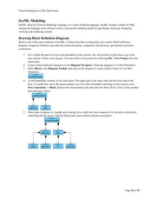
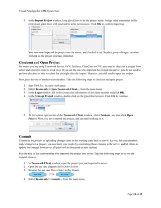
Code Generation
Java Round-Trip [Standard Edition or above]
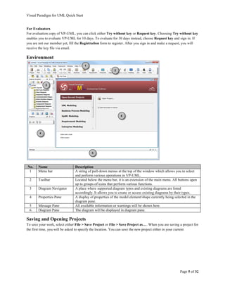
Round-trip engineering enables you to keep class model and source code in-sync. With Java round-trip, you can
reverse a code-base to VP-UML as class model, analyze, and make changes such as adding missing classes, and then
updating the changes to code, or vice versa.
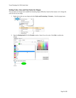
To generate Java source code from class model, select Tools > Code Engineering > Java Round-trip > Generate
Code… from the main menu. Enter the output path in the Generate code window and click OK to generate.
To reverse engineer a class from code, select Tools > Code Engineering > Java Round-trip > Reverse Code…
from the main menu. The Reverse Code window will pop up asking you to select a source file path. Click OK to
reverse.
C++ Round-Trip [Standard Edition or above]
To generate C++ for the whole project, click Tools > Code Engineering > C++ Round-trip > Generate Code…
from the main menu. The Generate Code window will pop up asking you to select a path, click the + button to add
a path. After selecting one, click OK to generate.
To reverse class model from code, select Tools > Code Engineering > C++ Round-trip > Reverse Code… from
the main menu. Select a source file path in the Reverse Code window and click OK to reverse.
Instant Generator [Standard Edition or above]
Instant generator produces source code from your model at a particular instant. Unlike the code generation support
in round-trip engineering, instant generator is a one-off. To generate code, select Tools > Code Engineering >
Instant Generator from the main menu, then select the programming language in which to generate.
Page 18 of 32](https://image.slidesharecdn.com/quickstartvpuml-120701145728-phpapp02/85/visual-paradigm-uml-18-320.jpg)
![Visual Paradigm for UML Quick Start
Instant Reverse [Standard Edition or above]
Instant Reverse allows you to reverse different types of source into UML class models, such as Java source, Java
classes, C++ source etc. To reverse, select Tools > Code Engineering > Instant Reverse from the main menu, then
select the appropriate programming language. Select the source files and proceed.
Instant Reverse Java Code to Sequence Diagram [Standard Edition or above]
Sequence diagram can help represent interactions between objects in runtime. VP-UML enables you to reverse your
Java source code to sequence diagram. You can gain a better understanding of a piece of Java source code by
reading its corresponding diagram, instead of looking at possibly a thousand lines of code. To reverse Java code to
sequence diagram, select Tools > Code Engineering > Instant Reverse > Java to Sequence Diagram… from the
main menu. Add the folder that contains the source code, continue and select the source file. Finally, visualize the
code in a new diagram.
Page 19 of 32](https://image.slidesharecdn.com/quickstartvpuml-120701145728-phpapp02/85/visual-paradigm-uml-19-320.jpg)
![Visual Paradigm for UML Quick Start
Reporting
Using Report Composer [Standard Edition or above]
You can develop professionally designed documentation using the Report Composer. Apart from the diagram-based
report generation function, you can customize a report by adding elements to your report manually.
1. Let’s continue with the QuickStart.vpp. Open the use case diagram Sales Order System. Create one if you
do not have one already.
2. Right-click on the diagram and select Utilities > Generate Use Case Report from the popup menu. This
creates a new report in report composer.
3. Scroll to the end of the report.
4. In the Diagram Navigator, press on the class diagram node Domain Model. Drag to the end of the report.
Page 20 of 32](https://image.slidesharecdn.com/quickstartvpuml-120701145728-phpapp02/85/visual-paradigm-uml-20-320.jpg)
![Visual Paradigm for UML Quick Start
The result should look something like this.
5. Click on the Export button at the top right and select Word Report….
6. In the Export Word Report window, fill in the output path and click Export to produce a Word.
Project Publisher [Standard Edition or above]
You can publish your project to Web format through the Project Publisher.
1. Select Tools > Project Publisher… from the main menu.
2. In the Project Publisher window, specify the output directory, which is the folder for storing the files to
publish.
3. Click OK. When finished, you can read the published content in a web browser.
Page 21 of 32](https://image.slidesharecdn.com/quickstartvpuml-120701145728-phpapp02/85/visual-paradigm-uml-21-320.jpg)
![Visual Paradigm for UML Quick Start
Advanced Modeling
Using Nicknamer [Standard Edition or above]
Nicknamer is a feature which helps you to present a model with labels in different languages. This is particularly
useful to multinational corporations where there’s often a need in presenting a model in multiple languages for
different regions. As localization is created on the fly when requested, there is no need to keep multiple versions for
different languages. That means you need to modify one version only if there are any changes.
1. Select View > Nicknames > Configure Nicknames… from the main menu.
2. In the Configure Nickname window, click Add User Language and select in the popup window a
language to add as nickname. E.g. Chinese (Traditional).
3. Click OK to close the popup window. Click OK again to return to the diagram. Modify the model for the
added nickname.
4. To open the English (original) version of the model. Select View > Nicknames > Original from the main
menu.
Page 28 of 32](https://image.slidesharecdn.com/quickstartvpuml-120701145728-phpapp02/85/visual-paradigm-uml-28-320.jpg)
![Visual Paradigm for UML Quick Start
Project Referencing [Standard Edition or above]
To avoid creating the same things (e.g. a class) over and over again, it would be useful to have a generic library to
keep components for reuse. When you make any changes to the components in the library, those changes will ripple
down to where the components are actually used. In VP-UML, we call this generic library a “Reference Project.”
1. Create a new project in VP-UML. You can create a new project by selecting File > New Project from the
main menu.
2. Right click on the background of Diagram Navigator/Model Explorer and select Manage Referenced
Project from the popup menu.
3. Click Add in the Manage Referenced Projects window. Select the QuickStart project to reference to.
4. Click Close.
5. The referenced project(s) are listed in the drop down menu at the top of the Model Explorer. You can
switch between the current project and the referenced project(s) through the drop down menu to see the
elements in them.
6. Create a new class diagram. Drag and drop the classes Customer, Order and Payment from Model
Explorer to the diagram. Make sure you have selected the referenced project in the drop down menu in
Page 29 of 32](https://image.slidesharecdn.com/quickstartvpuml-120701145728-phpapp02/85/visual-paradigm-uml-29-320.jpg)
![Visual Paradigm for UML Quick Start
Impact Analysis with Matrix [Professional Edition or above]
If you were to make a change to some model elements, it would be important to know which other elements will get
affected because of it. Impact Analysis can help you with that. There are three options, Matrix, Analysis Diagram
and Chart, to choose from, depending on the scope of the analysis you need. Matrix (diagram) is a tool that helps
you identify the relationship between model elements of specific type(s), so as to study the consequence of making
certain changes. Let’s try.
1. Continue with the QuickStart project (QuickStart.vpp). Create a matrix diagram via the Diagram
Navigator, under the category of Impact Analysis.
2. You need to configure the type of elements to list in rows and columns. Let’s say you want to delete some
classes and you want to be certain that such action won’t damage the integrity of the model. Therefore, you
want to see the relationships among classes. Select Class from the list of available models. Click on the
upper and lower arrow button to make classes list in both row and column.
3. You want to see the relationships (e.g. association, dependency, etc.) among classes. Select Relationship
for By (By here means to compare row and column items by the selected criterion)
4. Click OK. This produces a matrix which lists the classes in rows and columns, showing their relationships
in cells.
Page 31 of 32](https://image.slidesharecdn.com/quickstartvpuml-120701145728-phpapp02/85/visual-paradigm-uml-31-320.jpg)
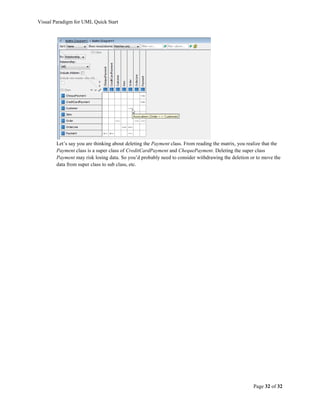

The document is a quick start guide for Visual Paradigm for UML (VP- UML), detailing installation, starting the application, workspace selection, and basic functions such as creating diagrams and model elements. It covers essential UML and SysML modeling techniques, including use case, sequence, activity, and class diagrams, along with code generation and collaborative features. Additionally, it instructs on saving projects, importing license keys, and customizing the user interface.