Principle of
Virtual Work
T. Sriyaratna Peiris
Principle of Virtual Work
T. Sriyaratna Peiris
Principle of Virtual Work
Principle of virtual work was developed by John Bernoulli in
1717.
Like other energy methods this is based on conservation of
energy.
The body is subjected to real loads , , .
𝐏𝟏 𝐏𝟐 𝐏𝟑
Consider the displacement
Δ at point A.
Δ cannot be included as an external work term in the equation
of conservation of energy.
If we place an imaginary or virtual force P’ on the body at
point A. P’ acts in the same direction as Δ. This load is
applied to the body before the real loads are applied.
This unit force can be designated as virtual force since it is
imaginary force.
This virtual load = 1 create an internal virtual load in one
𝑃 𝑢
of the representative elements in the structure.
When the virtual load is applied
and then the body is subjected to
the real loads P1,P2 and P3, point
A will be displaced a real amount
Δ, Which causes the element to
be displaced dL.
The external virtual load P’ and
internal virtual load U caused a
displacement of Δ and dL.
External virtual work on the body
= 1 x Δ
Internal virtual work on the
element = u x dL
According to the conservation of
energy;
External virtual work on the body
= Internal virtual work on the
element
Principle of Virtual Couple
Moment
If angular displacement or slope
of the tangent at a point on the
body
A virtual couple moment M’ of
unit magnitude is applied at the
point. It causes a virtual load uθ
in one of the elements of the
body.
Assuming the real loads ,
𝐏𝟏
, deform the element an
𝐏𝟐 𝐏𝟑
amount dL, the angular
displacement θ can be found
from the virtual work equation,
Internal Virtual
Work
Internal work developed in the body;
The real internal displacements dl in these tems can be produced
in several different ways.
1. Geometric fabrication errors
2. Change in temperature or more commonly
3. from stresses.
No restriction on magnitude of the external lading, so stress may
be large enough to cause yielding or even strain hardening of the
material.
Elastic strain energy & Internal virtual work for various types
of loading
The material is linear elastic and does
not exceed the proportional limit.
Internal loading N, V, M or T is applied
gradually from zero to its full value. As a
results the work done by these
resultants is shown in these
expressions as one half the product of
internal loading and its displacement.
In the case of the virtual loading full
virtual internal loading is applied before
the real load cause displacement.
Lowercase symbols n, v, m and t are
the virtual work due to axial load, shear,
bending moment and torsional moment.
The Virtual Work Equation
Conservation of Energy
A loading applied slowly to body , then physically the external
loads tend s to deform the body, and the loads do external
work Ue as t they are displaced. This external work on the body
is transformed into internal work or strain energy Ui, which is
stored in the body. When the loads are removed , the strain
energy restores the body back to its original undeformed
position within the elastic limit.
U e= Ui
Example - Beam
𝑈𝑖=∫
𝑀2
2 𝐸𝐼
𝑑𝑥
1
2
𝑃 Δ=∫
0
𝐿
𝑀
2
2 𝐸𝐼
𝑑𝑥
Beam loaded by a couple moment
1
2
𝑀 0 θ=∫
0
𝐿
𝑀
2
2 𝐸𝐼
𝑑𝑥
Methods of Virtual Forces Applied to
Trusses.
P1 and P2 are real loads are applied to the truss cause the
external virtual work 1.Δ. The internal virtual work in each
member is n ΔL and N and n are constant throughout the
member length.
Methods of Virtual Forces Applied to
Trusses.
Temperature Change
Fabrication Errors
Method of Virtual Forces Applied to
Beam
The vertical displacement
Δ of point the beam to be
determined.
Place vertical unit load at
this point.
Apply real distributed load
w on the load will cause
internal virtual work 1. Δ,
The lad causes both a
shear V and moment M
within the beam.
Internal virtual work due to both these loading.
Deflection s due to shear are negligible compared with those
caused by bending when the beam is long and slender.
Real load causes the element dx to deform and it sides rotate by
an angle Internal virtual work = mdθ,
Elastic Curve of the slope of the
tangent at a point on the beam
•
Example-1 Determine the
displacement of point B on the beam .
The virtual displacement of point B is
obtained by placing a virtual unit load at
B.
Virtual work equation.
Determine the slope at point B of the beam
Castigliano’s Second Theorem
• In 1879 Alberto Castigliano introduced this method to
determine the displacement and slope at a point in the body.
This is applied only to body at constant temperature and for the
linear elastic behaviour.
• This state that the displacement is equal to the first partial
derivative of the strain energy in the body with respect to the
force acting at that point and in the direction of displacement.
• In the similar manner the slope of the tangent at a point in a
body is equal to the first partial derivative of the strain energy in
the body with respect toa a couple moment acting at the pont
and in the direction of the slope angle.
Derivation of Castigliano’s 2nd
Theorem
• Consider a body of any arbitrary shape subjected to a series of
n forces P1, P2, …….Pn apply first and then dpj.
• Applying conservation of energy principle, the external work
done by these forces is equal to the internal strain energy
stored
Ui =Ue = f(P1, P2, …….Pn)
…….Eqn 1
Δj ……Eqn 2 Equating these two equations
Δj = Δj = Castigliano’s 2nd
Theorem.
The equation below represent the strain
energy in a body when dpj applied first and
then P1, P2, …….Pn .
Derivation of Castigliano’s 1st Theorem
• Similarly, we can prove 1st
theorem
= But it has very limited
applications
Castigliano’s Theorem Applied to
Trusses
Strain energy for the member is,
From Castigliano’s 2nd
theorem Δj =
Δ =
Δ =
Which is similar to
equation obtain for
virtual forces
1.Δ =
n is replaced by
Procedure for Analysis
1. External Force P
Place a force p on the truss at the joint, the displacement to be
determined. Force is assumed to be a variable magnitude and should be
along the line of action of the displacement.
2. Internal Force
Determine the force N in each member in terms of both the actual
(numerical) loads and variable force P. Tensile positive & Compressive
negative
Find the partial derivative for each member.
After N & determined, assign P its numerical value if it has actually
replaced a real force on the truss. Otherwise set to zero.
Procedure for Analysis. Cont..
3. Castigliano’s Theorem.
Apply Castigliano’s theorem to find the required displacement.
Retain the
algebraic sign for corresponding values of N and .
If the resultant sum is positive , Δ is in the same
direction as P,
otherwise opposite direction to P.
Exampl
e
Determine the vertical displacement of joint C of
the steel truss. The cross-sectional area of each
member is A = 400 mm2
and E = 200 GPa
Castigliano’s Theorem Applied to Beams
• The internal strain energy for beam is caused by both bending
and shear. If the beam is long and slender, the strain energy
due to shear can be neglected compared to that of the
bending.
• Assuming this to be the case , the internal strain energy for a
beam is given by;
• Omitting the subscript I, applying Castiglianos Theorem, Δj =
In addition , axial load, shear and torsion cause significant strain
energy within the member, then the effect of all these loading should
be included when applying Castigliano’s theorem.
The result is,
Procedure for Analysis
Castigliano’s Second Theorem
Apply , or
To determine the desired displacement θ or Δ.
Retaining the algebraic signs for corresponding
valves of M and or .
Example
Determine the displacement of point B on the beam shown below.
Example
Determine the slope at point B on the beam shown below.
Summary
Summary
Impact Loading
Important Points
Example
The aluminium pipe used to support a load of 600 kN.
Find the maximum displacement at the top of the pipe if
the load is (a) applied gradually, and (b) applied
suddenly by releasing it from the top of the pipe at h =
0.
Take Eal= 70(103
) Nmm2
and assume that the aluminium
behaves elastically.
Solution:
(a) Applying the conservation of energy, we have
Ue = Ui = = = = 0.5953 mm
• When h=0
= 1.19.6 mm

Virtu nnnnnnnnklojjnjnjjkokkal work.pptx

  • 1.
  • 2.
    Principle of VirtualWork T. Sriyaratna Peiris
  • 3.
    Principle of VirtualWork Principle of virtual work was developed by John Bernoulli in 1717. Like other energy methods this is based on conservation of energy. The body is subjected to real loads , , . 𝐏𝟏 𝐏𝟐 𝐏𝟑 Consider the displacement Δ at point A. Δ cannot be included as an external work term in the equation of conservation of energy. If we place an imaginary or virtual force P’ on the body at point A. P’ acts in the same direction as Δ. This load is applied to the body before the real loads are applied. This unit force can be designated as virtual force since it is imaginary force. This virtual load = 1 create an internal virtual load in one 𝑃 𝑢 of the representative elements in the structure.
  • 4.
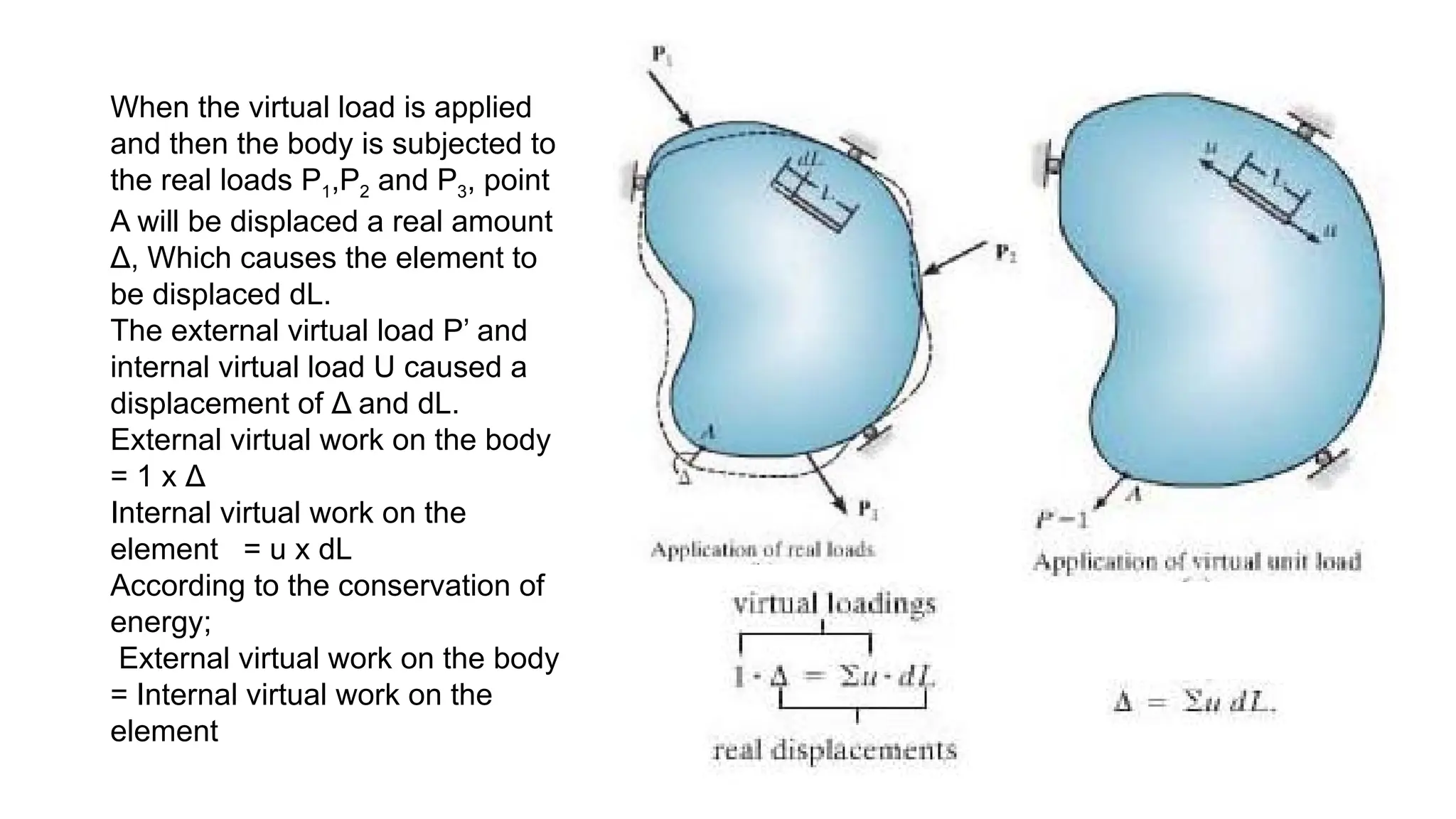
    When the virtualload is applied and then the body is subjected to the real loads P1,P2 and P3, point A will be displaced a real amount Δ, Which causes the element to be displaced dL. The external virtual load P’ and internal virtual load U caused a displacement of Δ and dL. External virtual work on the body = 1 x Δ Internal virtual work on the element = u x dL According to the conservation of energy; External virtual work on the body = Internal virtual work on the element
  • 5.
    Principle of VirtualCouple Moment If angular displacement or slope of the tangent at a point on the body A virtual couple moment M’ of unit magnitude is applied at the point. It causes a virtual load uθ in one of the elements of the body. Assuming the real loads , 𝐏𝟏 , deform the element an 𝐏𝟐 𝐏𝟑 amount dL, the angular displacement θ can be found from the virtual work equation,
  • 6.
    Internal Virtual Work Internal workdeveloped in the body; The real internal displacements dl in these tems can be produced in several different ways. 1. Geometric fabrication errors 2. Change in temperature or more commonly 3. from stresses. No restriction on magnitude of the external lading, so stress may be large enough to cause yielding or even strain hardening of the material.
  • 7.
    Elastic strain energy& Internal virtual work for various types of loading The material is linear elastic and does not exceed the proportional limit. Internal loading N, V, M or T is applied gradually from zero to its full value. As a results the work done by these resultants is shown in these expressions as one half the product of internal loading and its displacement. In the case of the virtual loading full virtual internal loading is applied before the real load cause displacement. Lowercase symbols n, v, m and t are the virtual work due to axial load, shear, bending moment and torsional moment.
  • 8.
  • 9.
    Conservation of Energy Aloading applied slowly to body , then physically the external loads tend s to deform the body, and the loads do external work Ue as t they are displaced. This external work on the body is transformed into internal work or strain energy Ui, which is stored in the body. When the loads are removed , the strain energy restores the body back to its original undeformed position within the elastic limit. U e= Ui
  • 10.
    Example - Beam 𝑈𝑖=∫ 𝑀2 2𝐸𝐼 𝑑𝑥 1 2 𝑃 Δ=∫ 0 𝐿 𝑀 2 2 𝐸𝐼 𝑑𝑥
  • 11.
    Beam loaded bya couple moment 1 2 𝑀 0 θ=∫ 0 𝐿 𝑀 2 2 𝐸𝐼 𝑑𝑥
  • 12.
    Methods of VirtualForces Applied to Trusses. P1 and P2 are real loads are applied to the truss cause the external virtual work 1.Δ. The internal virtual work in each member is n ΔL and N and n are constant throughout the member length.
  • 13.
    Methods of VirtualForces Applied to Trusses.
  • 14.
  • 15.
  • 16.
    Method of VirtualForces Applied to Beam The vertical displacement Δ of point the beam to be determined. Place vertical unit load at this point. Apply real distributed load w on the load will cause internal virtual work 1. Δ, The lad causes both a shear V and moment M within the beam.
  • 17.
    Internal virtual workdue to both these loading. Deflection s due to shear are negligible compared with those caused by bending when the beam is long and slender. Real load causes the element dx to deform and it sides rotate by an angle Internal virtual work = mdθ,
  • 18.
    Elastic Curve ofthe slope of the tangent at a point on the beam •
  • 19.
    Example-1 Determine the displacementof point B on the beam . The virtual displacement of point B is obtained by placing a virtual unit load at B.
  • 20.
  • 21.
    Determine the slopeat point B of the beam
  • 23.
    Castigliano’s Second Theorem •In 1879 Alberto Castigliano introduced this method to determine the displacement and slope at a point in the body. This is applied only to body at constant temperature and for the linear elastic behaviour. • This state that the displacement is equal to the first partial derivative of the strain energy in the body with respect to the force acting at that point and in the direction of displacement. • In the similar manner the slope of the tangent at a point in a body is equal to the first partial derivative of the strain energy in the body with respect toa a couple moment acting at the pont and in the direction of the slope angle.
  • 24.
    Derivation of Castigliano’s2nd Theorem • Consider a body of any arbitrary shape subjected to a series of n forces P1, P2, …….Pn apply first and then dpj. • Applying conservation of energy principle, the external work done by these forces is equal to the internal strain energy stored Ui =Ue = f(P1, P2, …….Pn) …….Eqn 1 Δj ……Eqn 2 Equating these two equations Δj = Δj = Castigliano’s 2nd Theorem. The equation below represent the strain energy in a body when dpj applied first and then P1, P2, …….Pn .
  • 25.
    Derivation of Castigliano’s1st Theorem • Similarly, we can prove 1st theorem = But it has very limited applications
  • 26.
    Castigliano’s Theorem Appliedto Trusses Strain energy for the member is, From Castigliano’s 2nd theorem Δj = Δ = Δ = Which is similar to equation obtain for virtual forces 1.Δ = n is replaced by
  • 27.
    Procedure for Analysis 1.External Force P Place a force p on the truss at the joint, the displacement to be determined. Force is assumed to be a variable magnitude and should be along the line of action of the displacement. 2. Internal Force Determine the force N in each member in terms of both the actual (numerical) loads and variable force P. Tensile positive & Compressive negative Find the partial derivative for each member. After N & determined, assign P its numerical value if it has actually replaced a real force on the truss. Otherwise set to zero.
  • 28.
    Procedure for Analysis.Cont.. 3. Castigliano’s Theorem. Apply Castigliano’s theorem to find the required displacement. Retain the algebraic sign for corresponding values of N and . If the resultant sum is positive , Δ is in the same direction as P, otherwise opposite direction to P.
  • 29.
    Exampl e Determine the verticaldisplacement of joint C of the steel truss. The cross-sectional area of each member is A = 400 mm2 and E = 200 GPa
  • 30.
    Castigliano’s Theorem Appliedto Beams • The internal strain energy for beam is caused by both bending and shear. If the beam is long and slender, the strain energy due to shear can be neglected compared to that of the bending. • Assuming this to be the case , the internal strain energy for a beam is given by; • Omitting the subscript I, applying Castiglianos Theorem, Δj =
  • 31.
    In addition ,axial load, shear and torsion cause significant strain energy within the member, then the effect of all these loading should be included when applying Castigliano’s theorem. The result is,
  • 32.
    Procedure for Analysis Castigliano’sSecond Theorem Apply , or To determine the desired displacement θ or Δ. Retaining the algebraic signs for corresponding valves of M and or .
  • 33.
    Example Determine the displacementof point B on the beam shown below.
  • 34.
    Example Determine the slopeat point B on the beam shown below.
  • 35.
  • 36.
  • 37.
  • 41.
  • 42.
    Example The aluminium pipeused to support a load of 600 kN. Find the maximum displacement at the top of the pipe if the load is (a) applied gradually, and (b) applied suddenly by releasing it from the top of the pipe at h = 0. Take Eal= 70(103 ) Nmm2 and assume that the aluminium behaves elastically. Solution: (a) Applying the conservation of energy, we have Ue = Ui = = = = 0.5953 mm • When h=0 = 1.19.6 mm