Download to read offline
![17
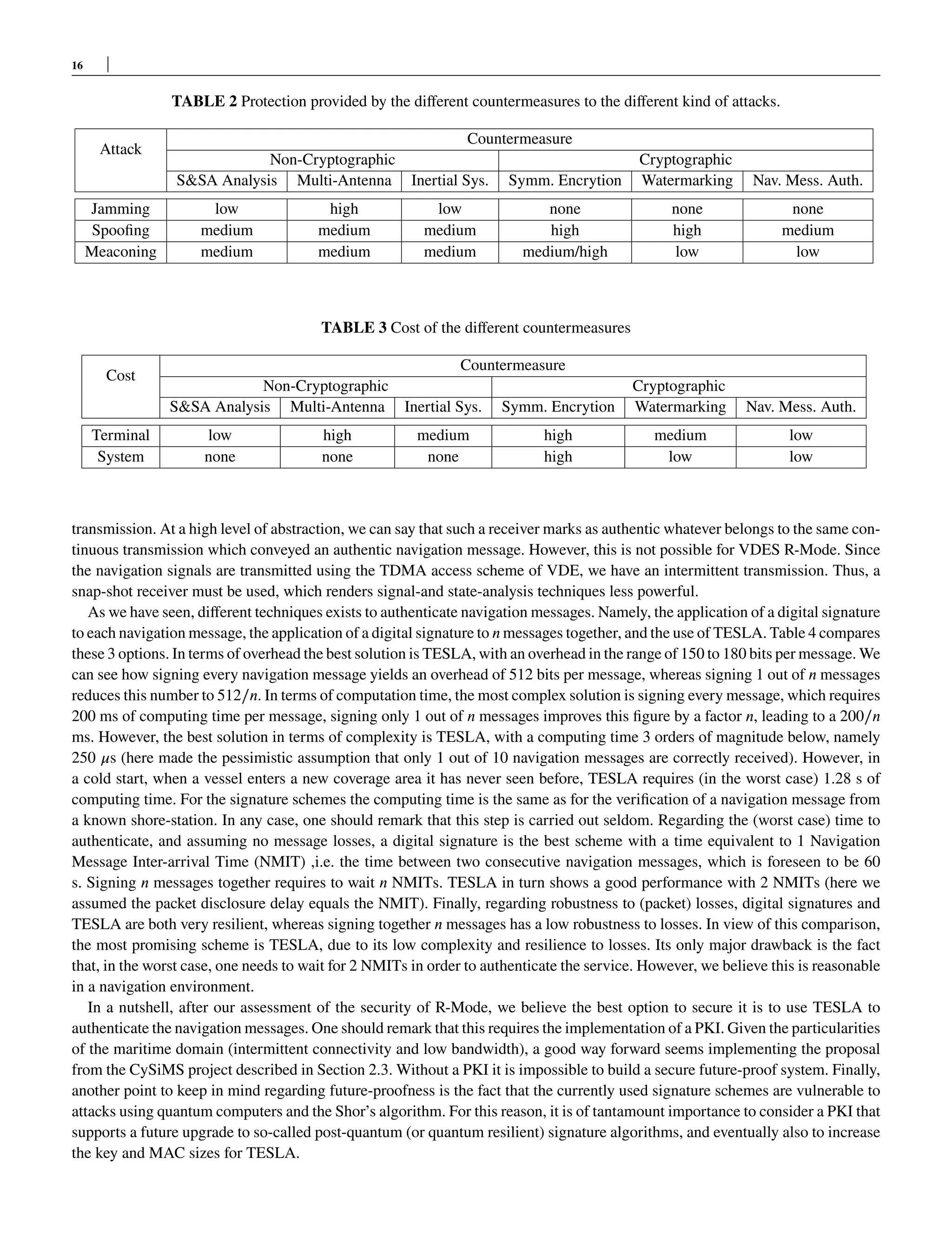
TABLE 4 Comparison of the direct application of signatures and TESLA for navigation message authentication.
dig. signatures 1-out-of-𝑛 dig. sign. TESLA
overhead per
nav. message [bits]
512 512∕𝑛 150-180
computation time per
authenticated nav. message
200 ms 200∕𝑛 ms 250 𝜇s
computation time
for cold start
200 ms 200∕𝑛 ms 1.28 s
Time to authenticate 1 NMIT 𝑛 NMIT 2 NMIT
Robustness to losses high low high
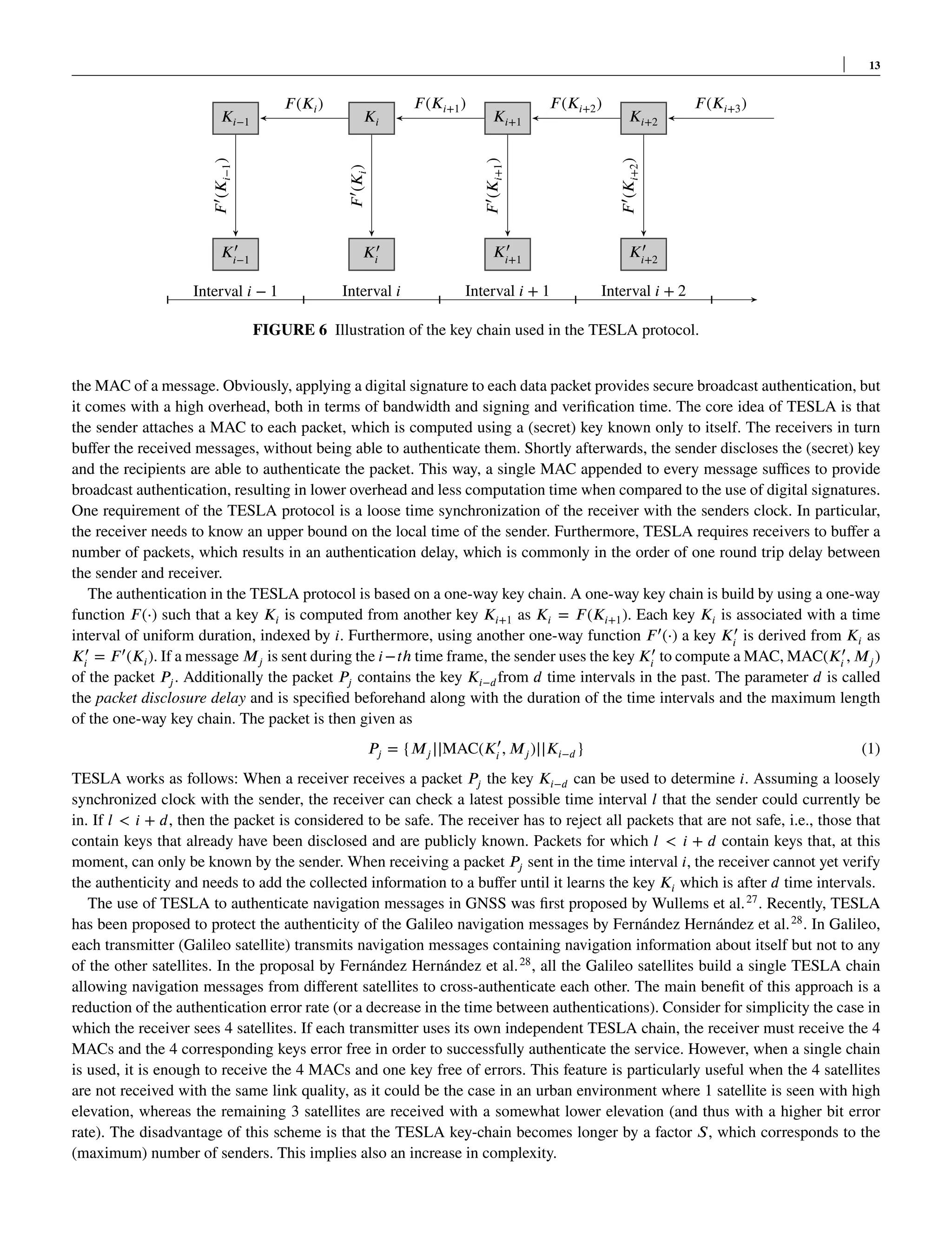
7 CONCLUSIONS
In this paper, we have studied the vulnerabilities of R-Mode, the contingency maritime positioning and navigation system that is
currently undergoing standardization through the International Association of Lighthouse Authorities (IALA). After analyzing
the different types of attacks that the system can be subject to, we have analyze the effectiveness of different cryptographic and
non-cryptographic countermeasures. Keeping in mind the fact that low terminal and system operation cost are of key importance
in order to foster the acceptance of the system, a promising solution seems authenticating the navigation messages of VDES R-
Mode using the TESLA protocol. Additionally, some receivers might optionally adopt some non-cryptographic countermeasures
to increase the level of protection.
DATA AVAILABILITY
Data sharing is not applicable to this article as no new data were created or analyzed in this study.
BIBLIOGRAPHY
References
1. Sadlier G, Flytkjær R, Sabri F, Herr D. The economic impact on the UK of a disruption to GNSS. tech. rep., Innovate UK;
2017.
2. IALA . R-129 GNSS VULNERABILITY AND MITIGATION MEASURES. tech. rep., IALA; 2012.
3. IALA . G1139 – THE TECHNICAL SPECIFICATION OF VDES. tech. rep., IALA; 2019.
4. Recommendation ITU-R M.1371-0 . Technical characteristics for a universal shipborne automatic identification system
using time division multiple access in the VHF maritime mobile band. ITU Tehcnical Report 1998.
5. Clazzer F, Lázaro F, Plass S. Enhanced AIS receiver design for satellite reception. CEAS Space Journal 2016; 8(4): 257–268.
6. Plass S, Poehlmann R, Hermenier R, Dammann A. Global maritime surveillance by airliner-based AIS detection:
preliminary analysis. The Journal of Navigation 2015; 68(6): 1195.
7. Safar J, Shaw G, Grant A, et al. GNSS Augmentation using the VHF Data Exchange System (VDES). In: ION. ; 2018.
8. IMO MSC-FAL1/Circ.3 . Guidelines on Maritime Cyber Risk Management. IMO 2017.
9. IMO MSC 98/23/Add.1 . Resolution MSC.428(98): Maritime Cyber Risk Management in Safety Management Systems.
IMO 2017.](https://image.slidesharecdn.com/vdesr-modevulnerabilityanalysisandmitigation-220802100354-38a43a24/75/VDES_R-Mode_Vulnerability_Analysis_and_Mitigation_-pdf-17-2048.jpg)

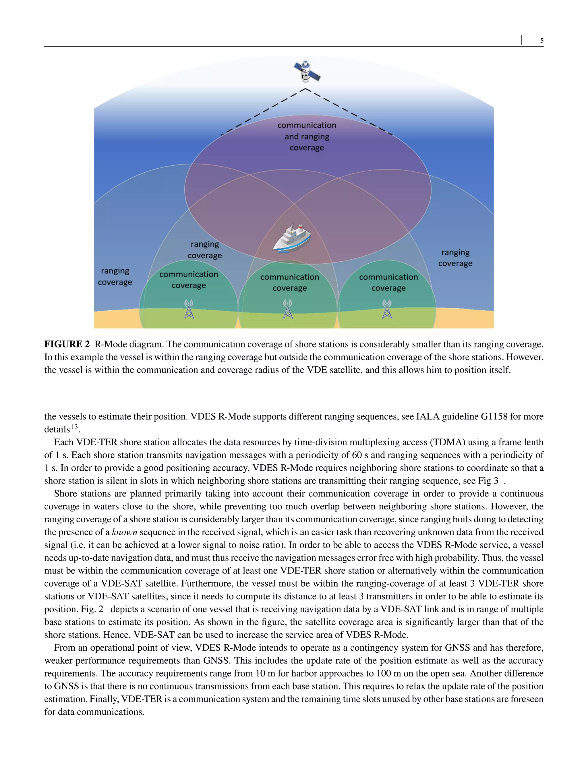
This document discusses the security vulnerabilities of VDES R-Mode, a contingency maritime positioning and navigation system that uses terrestrial infrastructure. It analyzes different types of attacks like jamming or spoofing that VDES R-Mode is susceptible to. The document recommends introducing authentication for R-Mode navigation messages using the TESLA protocol as the most promising countermeasure due to its good balance of complexity and security. It provides an overview of VDES, its security capabilities, and describes VDES R-Mode before assessing its security and discussing various cryptographic and non-cryptographic countermeasures.


![The Maritime Security. OSINT [EN] .pdf](https://cdn.slidesharecdn.com/ss_thumbnails/maritimesecurity-240723053511-8c070405-thumbnail.jpg?width=640&height=640&fit=bounds)


![Coded Agents – with UiPath SDK + LangGraph [Virtual Hands-on Workshop]](https://cdn.slidesharecdn.com/ss_thumbnails/codedagentsdeck-251215155422-5497c599-thumbnail.jpg?width=640&height=640&fit=bounds)


