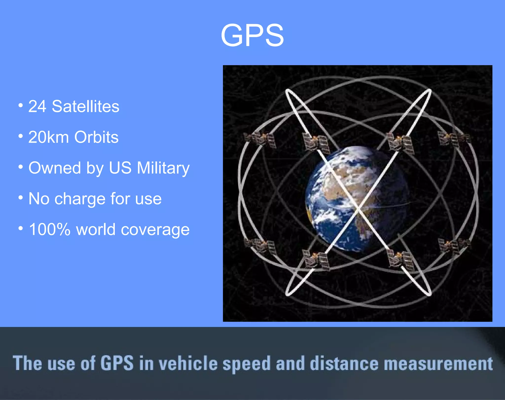
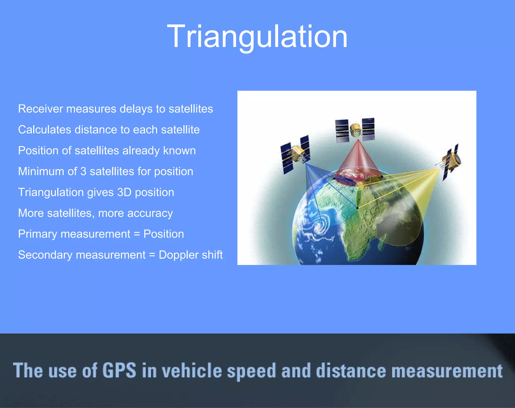
GPS
24 Satellites 20km Orbits Owned by US Military  No charge for use 100% world coverage GPS
Receiver measures delays to satellites Calculates distance to each satellite Position of satellites already known Minimum of 3 satellites for position Triangulation gives 3D position More satellites, more accuracy Primary measurement = Position Secondary measurement = Doppler shift Triangulation
Doppler  Shift
Speed from position
Doppler speed
What can you measure?
GPS derived measurements Non slip Velocity Position Height Distance True X,Y acceleration Side slip angle Radius of turn
What are the advantages?
The advantages of using GPS Small Lightweight Quick to fit Versatile Low power Robust Discrete
Used almost anywhere All weather conditions Independent of surface Anywhere in the world
GPS accuracy
Other sources of Error Hard Surface Direct Signal Reflected Signal Reflected Signal Satellite GPS Antenna
Accuracy  Velocity  ± 0.1km/h Distance ±0.05% Acceleration 0.5% Absolute position 3m
With Selective  Availability  X,Y position within 100m
Without  Selective  Availability  X,Y position within 3m
Calibration  Doppler simulator 12 satellite channels Repeatable Different simulations Constant speed Brake test High g cornering UKAS calibrated
Increasing Position Accuracy
Differential GPS  Fixed base station at known position Measures distances to satellites Corrects readings based on known position Corrections sent via radio or satellite
WAAS DGPS Coverage
Accuracies No DGPS 3m WAAS 1.5 m Local DGPS 0.5m
RTK GPS  Real Time Kinematic Fixed base station Limited baseline length <5km Dual frequency, L1 & L2 Corrections sent via radio 1cm XY accuracy, 2cm Z accuracy Track mapping ACC testing – distance between two vehicles
Sample rate
Sample rates available 1 Hz - route plotting only 5 Hz - general performance 20 Hz - brake testing 100Hz - transients/dynamics
Sample rate comparison
100Hz sample rate Lateral aquaplane tests Lane change manoeuvre 2 second test 20Hz - 40 samples 100Hz – 200 samples Suitable for Transients
Formula one car Maximum yaw rate = 150 degrees per second 100Hz sample rate Suitable for very high dynamics
Existing customers MIRA Millbrook Idiada Bosch  TUV Visteon BP Continental Teves (Auburn Hills USA & Germany) US Army Vickers defense QinetiQ Roush Industries Haldex Jatco Palmersport Martin Baker (Ejection seats) Rod Millen special vehicles BorgWarner Automotive International Truck and Engine Corporation  Transport Canada  PMG Technologies Chip Ganassi Racing TARRC Test World - Finland Windjet Speed Record Project  W S Atkins Rail  Helsinki University AP Hydraulics Car and Driver Popular Science  Automobile EVO  Autoexpress Autocar (UK) Autocar (NZ) Autocar (India)  Autocar (Greece) Autocar (Czech) Option Magazine (Japan) What Car Fast Ford Car and Car Conversions Fast Bike Performance BMW  Bike Magazine  BBC Top Gear TV ITV Pulling Power Motorcycle news Motor Magazine (Norway) Tekniikan Maailma-Magazine (Finland) Overdrive (India) Duke Video Driven(Thailand) Dunlop Goodyear Michelin Continental Tyres  Bridgestone Firestone  Kumho tyres (Korea & UK) Continental Nexen Nokian Ford GM Daimler Chrysler Mercedes BMW Ferrari Lamborghini Toyota Honda Volvo Saab Nissan Renault Yamaha  Aston Martin Hyundai Proton Iveco AMG Land Rover  Triumph Motorcycles Harley Davidson American Suzuki Ford Racing Volvo Penta  Renault F1 team TVS Motorcycles (India)  LML Motorcycles (India)
Applications
Distance is derived from velocity & time Accuracy ±5cm Very repeatable Also measure Longitudinal G & drift Brake assist development Brake testing
Traction control development  Time between two speeds ¼ mile time and terminal speed Vmax In gear times Performance testing
Lap time using virtual gates Split times Lateral G from radius & speed Driver line Circuit & driver analysis
Multifunction display Accel 0-60,50-70 etc Lap times/splits Printer function Brake stop, 100-0 etc Multiple test profiles  for quick and easy live  results.
CAN modules
Analogue inputs 24 bit A-D 8 channels  20Hz to 100Hz  ± 100mV to  ± 50V Opto-isolated, differential CAN output Fully configurable
Thermocouple inputs 24 bit A-D 8 channels -50 to +1200 degrees  0.1 degrees CAN output Fully configurable
Frequency/pulse inputs 4 Frequency inputs 0.5 – 25Khz Pulse counting TTL or inductive inputs CAN output Configurable Calculate wheelslip
Vehicle CAN Interface 16 CAN channels Fits any CAN bus Fully configurable CAN input/ CAN output OEM Data sets available
Vehicle CAN Interface Mercedes BMW Audi Volkswagen  Porsche Ferrari SAAB Vauxhall Jaguar Fiat Alfa Renault Citroen Peugeot Ford
YAW SENSOR Yaw rate range ±150°/s  Acceleration range ±1.7g in each axis Internal temperature compensation Yaw rate resolution 0.01°/s Acceleration resolution 1mg CAN Bus interface The YAW02 is designed for use with VBOXII, VBOX-III or as a stand-alone sensor with simple connection and configuration via the CAN bus interface.
INERTIAL MEASUREMENT UNIT ( IMU) Yaw, Pitch and Roll rate range ±150°/s Acceleration range ±1.7g in each axis Internal temperature compensation Yaw, Pitch and Roll rate resolution 0.01°/s Acceleration resolution 1mg  CAN Bus interface  The IMU01 is designed for use with VBOXII, VBOX-III or as a stand-alone sensor with simple connection and configuration via the CAN bus interface.
VBOX Slip Angle Sensor Velocity Position Distance X & Y Acceleration Slip angle Pitch or Roll angle Lateral velocity Yaw rate By closely coupling two 20Hz GPS engines, the VBOX Slip Angle Sensor can measure the following:
How does it work? The two antennas are placed at an exact distance apart
How does it work? The angle the vehicle is pointing is calculated using trigonometry.
How does it work? The direction the vehicle is travelling is the Course over Ground of the primary antenna
How does it work? The slip angle is the difference between the two
Where is the slip measured? The slip angle measured at the primary antenna
Where can the antennas be placed? The primary antenna is placed anywhere, as long as it is a known distance from the secondary antenna. Any misalignment to straight ahead is calibrated out in a simple operation, allowing the antennas to be placed in any orientation. If the antenna is not fixed to the roof, an antenna with an internal ground plane must be used (as shown).
How good is the pitch measurement? In the example above, the small pitch variations ( ±0.6)º  during a gear change can be clearly seen.
How can I measure Roll? Place the antennas at 90º to the direction of travel, Slip and Roll are now measured.
What are the accuracies? The accuracies depend on the separation between the antennas: 0.5 m separation gives 0.5º 1.0m separation gives 0.25º 2.0m separation gives 0.1º
What kind of tests can it be used to measure ? The 20Hz sample rate gives plenty of detail even in a very fast manoeuvre such as a violent lane change shown above, note the very large yaw rate and jerk rate.
Does it need constant alignment ? The Slip Angle Sensor can be used indefinitely during vehicle testing without any need for alignment due to the absolute measurement of heading obtained using the two antennas
What outputs are available? 2 x 16 bit analogue outputs 2 x 24 bit digital outputs CAN output RS232 output The Slip Angle Sensor can be connected to a VBOX which will then log all the measured parameters.
Recent Product Releases Differential Base  Station Standard RTCM output Integrated radio transmitter 25 Position memory Self survey mode Battery or external power Supplied with radio receiver Rugged IP64 Enclosure
CAN Display Compact Size Simple graphical interface Use standard DBC database files Display raw CAN data or database signals Automatically detects CAN bit/s Scan CAN Bus for lists of all identifiers Recent Product Releases
Recent Product Releases File Manager Simple graphical interface VBOX filenames can be configured by the user Unwanted files can be deleted after each test Graphical speed display Set logging modes without laptop
Windows s/w Flexible graphs Circuit plots Results tables Live Windows Live results
Live Windows
Report generator
GPS Extremely versatile Accurate Very convenient GPS now accepted as a means of measuring speed and distance by an increasing number of automotive companies.  The VBOX is used by BMW, Daimler Chrysler, GM, Ford, Michelin, Goodyear, Bosch, Visteon, Idiada, MIRA etc. More satellites and more processing power means GPS is only going to get better.
 

Vbox Training Presentation

  • 1.
  • 2.
  • 3.
    24 Satellites 20kmOrbits Owned by US Military No charge for use 100% world coverage GPS
  • 4.
    Receiver measures delaysto satellites Calculates distance to each satellite Position of satellites already known Minimum of 3 satellites for position Triangulation gives 3D position More satellites, more accuracy Primary measurement = Position Secondary measurement = Doppler shift Triangulation
  • 5.
  • 6.
  • 7.
  • 8.
    What can youmeasure?
  • 9.
    GPS derived measurementsNon slip Velocity Position Height Distance True X,Y acceleration Side slip angle Radius of turn
  • 10.
    What are theadvantages?
  • 11.
    The advantages ofusing GPS Small Lightweight Quick to fit Versatile Low power Robust Discrete
  • 12.
    Used almost anywhereAll weather conditions Independent of surface Anywhere in the world
  • 13.
  • 14.
    Other sources ofError Hard Surface Direct Signal Reflected Signal Reflected Signal Satellite GPS Antenna
  • 15.
    Accuracy Velocity ± 0.1km/h Distance ±0.05% Acceleration 0.5% Absolute position 3m
  • 16.
    With Selective Availability X,Y position within 100m
  • 17.
    Without Selective Availability X,Y position within 3m
  • 18.
    Calibration Dopplersimulator 12 satellite channels Repeatable Different simulations Constant speed Brake test High g cornering UKAS calibrated
  • 19.
  • 20.
    Differential GPS Fixed base station at known position Measures distances to satellites Corrects readings based on known position Corrections sent via radio or satellite
  • 21.
  • 22.
    Accuracies No DGPS3m WAAS 1.5 m Local DGPS 0.5m
  • 23.
    RTK GPS Real Time Kinematic Fixed base station Limited baseline length <5km Dual frequency, L1 & L2 Corrections sent via radio 1cm XY accuracy, 2cm Z accuracy Track mapping ACC testing – distance between two vehicles
  • 24.
  • 25.
    Sample rates available1 Hz - route plotting only 5 Hz - general performance 20 Hz - brake testing 100Hz - transients/dynamics
  • 26.
  • 27.
  • 28.
    100Hz sample rateLateral aquaplane tests Lane change manoeuvre 2 second test 20Hz - 40 samples 100Hz – 200 samples Suitable for Transients
  • 29.
    Formula one carMaximum yaw rate = 150 degrees per second 100Hz sample rate Suitable for very high dynamics
  • 30.
    Existing customers MIRAMillbrook Idiada Bosch TUV Visteon BP Continental Teves (Auburn Hills USA & Germany) US Army Vickers defense QinetiQ Roush Industries Haldex Jatco Palmersport Martin Baker (Ejection seats) Rod Millen special vehicles BorgWarner Automotive International Truck and Engine Corporation Transport Canada PMG Technologies Chip Ganassi Racing TARRC Test World - Finland Windjet Speed Record Project W S Atkins Rail Helsinki University AP Hydraulics Car and Driver Popular Science Automobile EVO Autoexpress Autocar (UK) Autocar (NZ) Autocar (India) Autocar (Greece) Autocar (Czech) Option Magazine (Japan) What Car Fast Ford Car and Car Conversions Fast Bike Performance BMW Bike Magazine BBC Top Gear TV ITV Pulling Power Motorcycle news Motor Magazine (Norway) Tekniikan Maailma-Magazine (Finland) Overdrive (India) Duke Video Driven(Thailand) Dunlop Goodyear Michelin Continental Tyres Bridgestone Firestone Kumho tyres (Korea & UK) Continental Nexen Nokian Ford GM Daimler Chrysler Mercedes BMW Ferrari Lamborghini Toyota Honda Volvo Saab Nissan Renault Yamaha Aston Martin Hyundai Proton Iveco AMG Land Rover Triumph Motorcycles Harley Davidson American Suzuki Ford Racing Volvo Penta Renault F1 team TVS Motorcycles (India) LML Motorcycles (India)
  • 31.
  • 32.
    Distance is derivedfrom velocity & time Accuracy ±5cm Very repeatable Also measure Longitudinal G & drift Brake assist development Brake testing
  • 33.
    Traction control development Time between two speeds ¼ mile time and terminal speed Vmax In gear times Performance testing
  • 34.
    Lap time usingvirtual gates Split times Lateral G from radius & speed Driver line Circuit & driver analysis
  • 35.
    Multifunction display Accel0-60,50-70 etc Lap times/splits Printer function Brake stop, 100-0 etc Multiple test profiles for quick and easy live results.
  • 36.
  • 37.
    Analogue inputs 24bit A-D 8 channels 20Hz to 100Hz ± 100mV to ± 50V Opto-isolated, differential CAN output Fully configurable
  • 38.
    Thermocouple inputs 24bit A-D 8 channels -50 to +1200 degrees 0.1 degrees CAN output Fully configurable
  • 39.
    Frequency/pulse inputs 4Frequency inputs 0.5 – 25Khz Pulse counting TTL or inductive inputs CAN output Configurable Calculate wheelslip
  • 40.
    Vehicle CAN Interface16 CAN channels Fits any CAN bus Fully configurable CAN input/ CAN output OEM Data sets available
  • 41.
    Vehicle CAN InterfaceMercedes BMW Audi Volkswagen Porsche Ferrari SAAB Vauxhall Jaguar Fiat Alfa Renault Citroen Peugeot Ford
  • 42.
    YAW SENSOR Yawrate range ±150°/s Acceleration range ±1.7g in each axis Internal temperature compensation Yaw rate resolution 0.01°/s Acceleration resolution 1mg CAN Bus interface The YAW02 is designed for use with VBOXII, VBOX-III or as a stand-alone sensor with simple connection and configuration via the CAN bus interface.
  • 43.
    INERTIAL MEASUREMENT UNIT( IMU) Yaw, Pitch and Roll rate range ±150°/s Acceleration range ±1.7g in each axis Internal temperature compensation Yaw, Pitch and Roll rate resolution 0.01°/s Acceleration resolution 1mg CAN Bus interface The IMU01 is designed for use with VBOXII, VBOX-III or as a stand-alone sensor with simple connection and configuration via the CAN bus interface.
  • 44.
    VBOX Slip AngleSensor Velocity Position Distance X & Y Acceleration Slip angle Pitch or Roll angle Lateral velocity Yaw rate By closely coupling two 20Hz GPS engines, the VBOX Slip Angle Sensor can measure the following:
  • 45.
    How does itwork? The two antennas are placed at an exact distance apart
  • 46.
    How does itwork? The angle the vehicle is pointing is calculated using trigonometry.
  • 47.
    How does itwork? The direction the vehicle is travelling is the Course over Ground of the primary antenna
  • 48.
    How does itwork? The slip angle is the difference between the two
  • 49.
    Where is theslip measured? The slip angle measured at the primary antenna
  • 50.
    Where can theantennas be placed? The primary antenna is placed anywhere, as long as it is a known distance from the secondary antenna. Any misalignment to straight ahead is calibrated out in a simple operation, allowing the antennas to be placed in any orientation. If the antenna is not fixed to the roof, an antenna with an internal ground plane must be used (as shown).
  • 51.
    How good isthe pitch measurement? In the example above, the small pitch variations ( ±0.6)º during a gear change can be clearly seen.
  • 52.
    How can Imeasure Roll? Place the antennas at 90º to the direction of travel, Slip and Roll are now measured.
  • 53.
    What are theaccuracies? The accuracies depend on the separation between the antennas: 0.5 m separation gives 0.5º 1.0m separation gives 0.25º 2.0m separation gives 0.1º
  • 54.
    What kind oftests can it be used to measure ? The 20Hz sample rate gives plenty of detail even in a very fast manoeuvre such as a violent lane change shown above, note the very large yaw rate and jerk rate.
  • 55.
    Does it needconstant alignment ? The Slip Angle Sensor can be used indefinitely during vehicle testing without any need for alignment due to the absolute measurement of heading obtained using the two antennas
  • 56.
    What outputs areavailable? 2 x 16 bit analogue outputs 2 x 24 bit digital outputs CAN output RS232 output The Slip Angle Sensor can be connected to a VBOX which will then log all the measured parameters.
  • 57.
    Recent Product ReleasesDifferential Base Station Standard RTCM output Integrated radio transmitter 25 Position memory Self survey mode Battery or external power Supplied with radio receiver Rugged IP64 Enclosure
  • 58.
    CAN Display CompactSize Simple graphical interface Use standard DBC database files Display raw CAN data or database signals Automatically detects CAN bit/s Scan CAN Bus for lists of all identifiers Recent Product Releases
  • 59.
    Recent Product ReleasesFile Manager Simple graphical interface VBOX filenames can be configured by the user Unwanted files can be deleted after each test Graphical speed display Set logging modes without laptop
  • 60.
    Windows s/w Flexiblegraphs Circuit plots Results tables Live Windows Live results
  • 61.
  • 62.
  • 63.
    GPS Extremely versatileAccurate Very convenient GPS now accepted as a means of measuring speed and distance by an increasing number of automotive companies. The VBOX is used by BMW, Daimler Chrysler, GM, Ford, Michelin, Goodyear, Bosch, Visteon, Idiada, MIRA etc. More satellites and more processing power means GPS is only going to get better.
  • 64.