Download to read offline
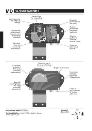
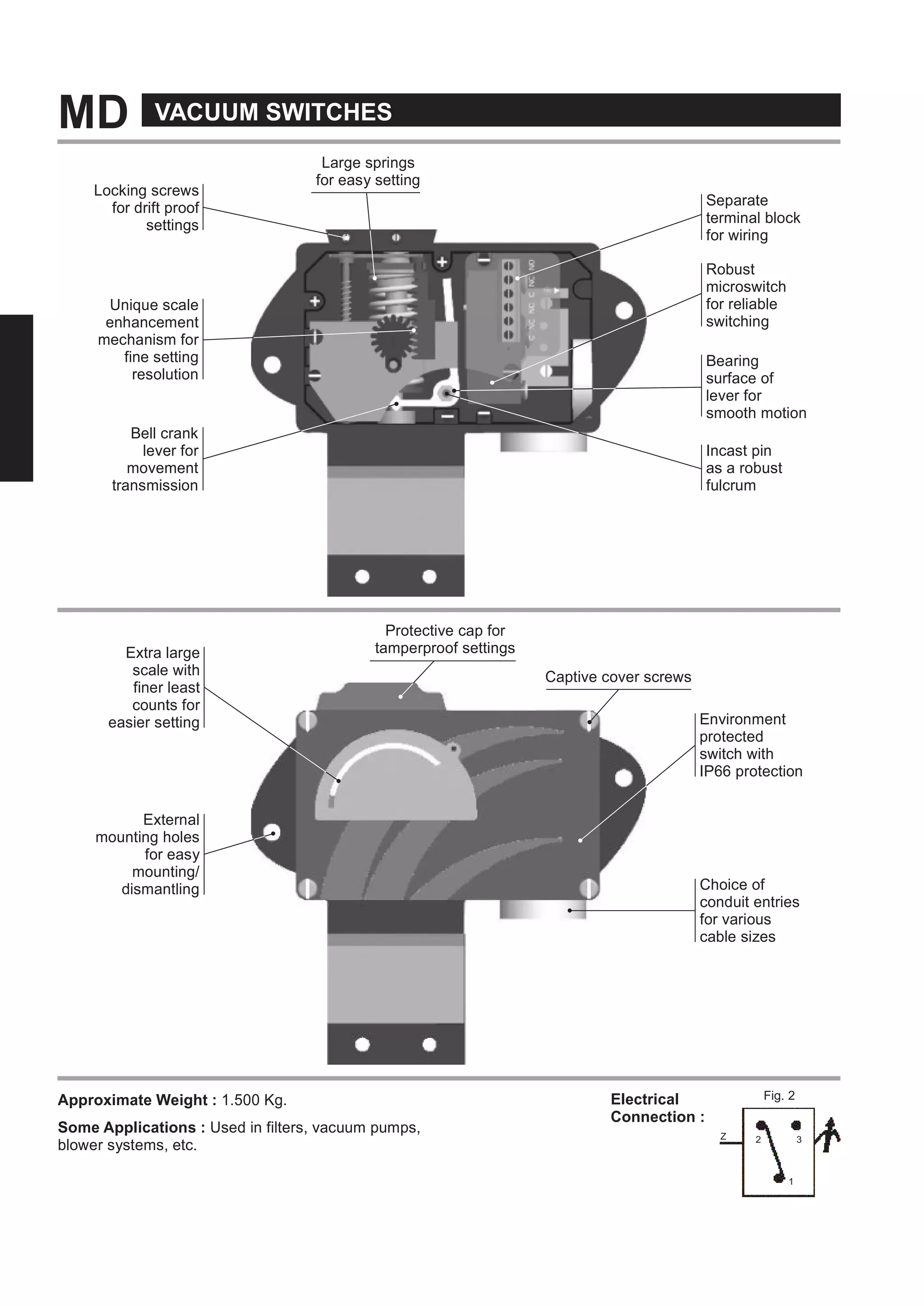
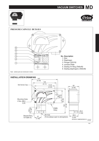

The document details md vacuum switches, highlighting their features such as locking screws for drift proof settings, unique scale mechanisms, and robust microswitches for reliable operation. It includes specifications like dimensions, weight, working pressure, and applications in systems like vacuum pumps and filters. Additionally, it provides contact information for the manufacturer, including email and website details.


