Download to read offline
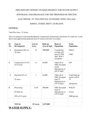

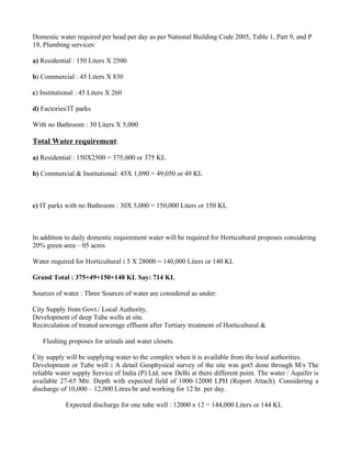
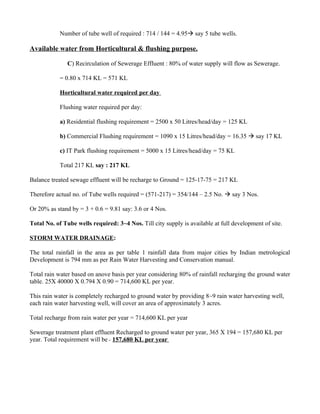
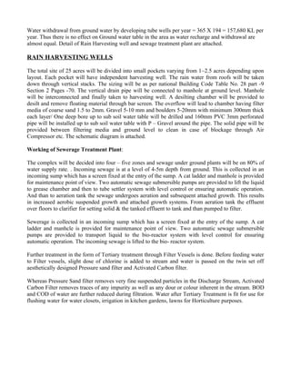

The document provides details on the water supply, sewerage, drainage and power requirements for a proposed special economic zone in Sohna, Haryana. It estimates that the total water requirement will be 714 kilolitres per day to meet the needs of residential, commercial, institutional and IT developments. Storm water drainage and rainwater harvesting systems are also described to recharge groundwater and maintain water balance. The power demand for the development is estimated to be 9 megawatts, sourced from the local grid and distributed via an 11kV network. Street lighting designs and operations are outlined.


