4. US 8,890,016 B2
1
TOUCH PAD DEVICE
The present invention is an operating button attachment for
electronic devices. The present application claims the bene?t
of Provisional Patent Application 61/425,532 ?led Dec. 21,
2010.
BACKGROUND OF THE INVENTION
Numerous electronic devices use designated input areas,
often in the form of “buttons” to which ?nger pressure is
applied and interpreted to enter a command, and as the sup
porting technology has expanded, the use to which a single
input element can be put has expanded. For example, when
Apple Inc.’s iPhone operating system was introduced in
2007, its input button, the “home” button, was simply used to
exit an application and return to the home screen. Subsequent
advancements, such as Apple’ s iOS 4 operating system, intro
duced to the public in 2010, provided for multi-tasking. Such
increased functionality incorporated “double clicking” the
home button to switch between applications. The home but
ton thus has matured to the point where it is now a multi
function/multi purpose input/control element, having func
tionality that has expanded farbeyond its original single click
purpose to return “home”. Other electronics devices of other
manufacturers have or can be expected to adopt similar func
tionality, providing a single (or several) button(s) to perform
a plurality of tasks and/or enter a variety of commands, par
ticularly in portable devices in which available space for
operating controls may be at a premium.
While use of such operating buttons has increased, they
often have an upper contact surface which is recessed from
the surrounding bezel or surface on which the button is
mounted. While such a construction provides for a degree of
security against inadvertent contact, it often hinders effective
contact, and offers little in the way oftactile feedback.
Because of the multi-tasking feature of a home button or
similar tactile input device, the button is used on a continuous
basis, and it is important that the user have increased control
and comfort in using the button. In addition, it would be
advantageous to provide a button with means by which it can
be easily tactilely identi?ed. This can be ofparticular bene?t
when a group of buttons is present, whereby a particular
button can be differentiated in a tactile manner to con?rm its
location and identity. Improving the tactile quality ofoperat
ing buttons may also be of bene?t to the visually impaired.
BRIEF DESCRIPTION OF THE INVENTION
In accordance with the forgoing and other bene?ts, the
present invention allows for easier use ofan operating button;
such as in “double clicking” or applying a directed force to the
button to control, for example, a displayed cursor when the
button functions as a peripheral device. The invention is a disc
shaped device with an adhesive backing, allowing the device
to be af?xed to the “home” or other designated control button
on an electronics device. The device is intended to be applied
to any electronic ormechanical device control button, and can
be ofa variety ofshapes, although in a preferred form it is disc
shaped.
When applied to a device’s operating button, access to the
button is enhanced, and the surface texture of the device can
improve the reliability ofthe intended operation as well as the
tactile response to the user.
BRIEF DESCRIPTION OF DRAWINGS
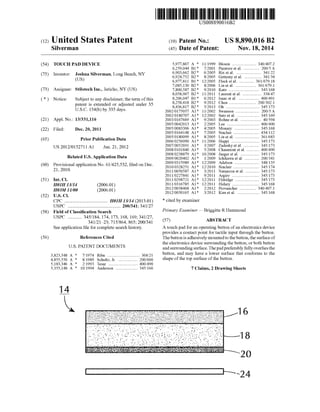
FIG. 1 is a perspective view ofa mobile electronics device
with the invention in place thereon;
20
25
30
35
40
45
50
55
60
65
2
FIG. 2 is a top plan view ofthe device of FIG. 1;
FIG. 3 is an elevation view of the invention;
FIG. 4 is an illustration ofhow the invention may be oma
mented; and
FIG. 5 is a cross-sectional view ofa preferred embodiment
ofthe invention.
DETAILED DESCRIPTION OF THE INVENTION
As shown in FIGS. 1 and 2, 10 is a representative mobile
electronics device, such as a cell phone. In addition to the
device’s screen 12, which may be touch-sensitive, a “home”
button is provided towards the lower edge of the device’s
front face surface 22. The button may be recessed from the
surrounding surface and can be dif?cult to access. In the
Figures the button is shown overlaid with the present inven
tion 14. It completely covers the button, providing a raised
area that can be easily contacted and which transmits the
applied ?nger pressure to the button which it overlies.
As depicted in the Figures, the device may preferably be in
the form of a disc, the general construction of which may be
seen in FIG. 3, intended to generally conform to the outline
shape ofthe button over which it is positioned. The disc has a
top layer 16, the top surface of which accepts the ?nger
pressure ofthe user. The top layer may be formed ofa variety
of materials, including coarse fabrics, as well as materials
with other textures, such as grooved rubber and foam.
Depending on the nature of the top layer, a backing layer 18
may also be used to provide additional thickness to the device
and/or to further control the tactile response ofthe device. For
example, the backing layer may be offoam to provide further
?exibility and cushioning. Alternatively, if the upper layer
itselfhas suf?cient ?exibility, the backing layer may be a less
resilient material, serving primarily to raise the top layer.
Bottom layer 20 is an adhesive that allows the device 14 to
be a?ixed to the operating button which it overlies. Typically,
the adhesive, as known in the art, is applied directly to the
adjoining layer 18 (or 16). A removable liner 24 initially
covers the bottom surface of the adhesive layer, and is
removed by the user to expose the adhesive when the device
is to be installed on the electronic device.
The diameter ofthe device 14 may be varied as appropriate
to accommodate operating buttons of various sizes. A diam
eter of about 9.5 m (3/8"), for example, may be appropriate
for installation on the Apple Inc. iPhone product. As depicted
in FIG. 4, the top surface ofthe device may be imprinted with
a logo or design to customize the device. In addition, the top
layer 16 can be colored or otherwise decorated using any
technique as known in the art. In addition to being round, the
shape of the device may likewise be varied. Square, rectan
gular and hexagonal shapes in plan, for example, may be
employed. So long as the operating button with which the
device is to be used is adequately overlaid, the shape of the
device may be varied as desired.
While as shown in FIG. 3 the adhesive layer 20 is coexten
sive with the area of the bottom surface of the layer upon
which it lies, it need not be. The adhesive may be in the form
of a ring or central spot. In addition, in conjunction with the
size ofthe device 14 itself, which may be sized to overlie only
the intended operating button or both the button and a portion
ofthe surrounding surface 22, the adhesive may be sized and
located to adhere the device 14 to the button, the button’s
surrounding surface, or both.
FIG. 5 presents a cross-sectional view of a preferred
embodiment, as may be used, for example on an Apple Inc.
iPhone unit. The device 26 is circular in plan, constructed of
silicone rubber, and may have a diameter of 13.2 mm and an
5. US 8,890,016 B2
3
overall thickness of 1.5 mm. The major portion of the upper
surface is ?at, with sloping peripheral edge 28 ofabout 1 mm
in width. The intersection between the ?at central portion and
the edge 28 may bear a radius of0.5 mm. The bottom surface
ofthe device may be contoured to more readily accommodate
a depressed operating button. Thus, the bottom central sur
face portion 30 is arcuate, with a contour that complements
that of the upper surface of the button which it is to contact.
The central portion is surroundedby planarperipheral rim 32,
1 mm in width. In general the depth of the central portion 10
below the rim is on the order of 0.5 mm.
The construction of FIG. 5 is intended to overlie both the
corresponding button and a portion of the surrounding unit
surface. Thus, the adhesive layer (not shown) may preferably
be provided at the bottom rim 32. It may, however, also extend 15
onto the central portion 30 to allow device attachment directly
to the overlaid button.
As set forth herein, the present invention adds functionality
and design customization to the device upon which it is
installed and with it is used, providing easier button location 20
and more comfortable clicking.
I claim:
1. A touch pad for an operating button of an electronics
device, comprising:
5
4
a ?rst layer with an upper surface providing a contact point
for user tactile input;
an adhesive layer for af?xing the touch pad to the operating
button; and
an intermediate layerpositioned between the ?rst layer and
the adhesive layer.
2. The touch pad of claim 1, wherein the ?rst layer is of
silicone rubber.
3. The touch pad ofclaim 1 wherein the intermediate layer
is of foam.
4. The touch pad of claim 1, wherein the ?rst layer has a
size in plan equal or greater than the size in plan of the
operating button.
5. The touch pad of claim 4, wherein the ?rst layer is
circular in plan.
6. The touch pad of claim 4, wherein the adhesive layer is
coextensive with the size of the ?rst layer.
7. The touch pad of claim 4, wherein the size of the ?rst
layer is greater than the size ofthe operating button to further
overlie a portion of a surrounding surface of the electronics
device, the adhesive layerbeing locatedto alignwith only one
ofthe operating button or surrounding surface.
* * * * *