SlideShare a Scribd company logo
1 of 31
Download to read offline
USOO6474099B2
(12) United States Patent (10) Patent No.: US 6,474,099 B2
Tanaka et al. (45) Date of Patent: Nov. 5, 2002
(54) ADSORPTION-TYPE COOLING APPARATUS 5,351,493 A * 10/1994 Hiro et al. ................... 62/46.2
5,463.879 A 11/1995 Jones .......................... 62/480
(75) Inventors: Masaaki Tanaka, Nagoya (JP); Satoshi
Inoue, Kariya (JP); Hideaki Sato, Anjo
(JP); Katsuya Ishii, Anjo (JP); Hisao
Nagashima, Okazaki (JP); Shin Honda,
Nagoya (JP); Takahisa Suzuki, Kariya
(JP)
(73) Assignee: Denso Corporation, Kariya (JP)
(*) Notice: Subject to any disclaimer, the term ofthis
patent is extended or adjusted under 35
U.S.C. 154(b) by 0 days.
(21) Appl. No.: 09/734,845
(22) Filed: Dec. 11, 2000
(65) Prior Publication Data
US 2002/003.5849 A1 Mar. 28, 2002
(30) Foreign Application Priority Data
Dec. 17, 1999 (JP) ........................................... 11-359761
Feb. 28, 2000 (JP) ....................................... 2OOO-056055
(51) Int. Cl." ................................................. F25B 17/08
(52) U.S. Cl. ............................................ 62/480; 62/476
(58) Field of Search .......................... 62/480, 481,476,
62/477, 335, 101, 106
(56) References Cited
U.S. PATENT DOCUMENTS
5,157,938 A * 10/1992 Bard et al..................... 62/335
5
5.Af.1987 to
|
5,775,126 A 7/1998 Sato et al.
* cited by examiner
Primary Examiner Denise Esquivel
ASSistant Examiner Melvin Jones
(74) Attorney, Agent, or Firm-Harness, Dickey & Pierce,
PLC
(57) ABSTRACT
The present invention provides an adsorption-type cooling
apparatus comprising first, Second, third, and fourth adsorp
tion devices filled with a coolant and contain adsorbents
which adsorb evaporated coolant and desorb the adsorbed
coolant during heating. Adsorption cores provide heat
eXchange between the adsorbents and a heat medium, and
evaporation and condensation cores provide heat eXchange
between heating medium and the coolant. A cooling device
in which heating medium cooled in the evaporation and
condensation cores circulates and cools the object of cool
ing. A heating means Supplies a high-temperature heat
medium to the first-fourth adsorption devices. A cooling
means Supplies a low-temperature heat medium which has a
temperature lower than that of the high-temperature heat
medium to the first-fourth adsorption devices. Also, a
Switching control means is provided which Switches
between multiple States.
6 Claims, 22 Drawing Sheets
93 it
Also, (
Lungwani (JP)KariyaMuungo,
U.S. Patent Nov.5, 2002 Sheet 1 of22 US 6,474,099 B2
94
NDs
J.E.E.SSSS S5.N
Aft
U.S. Patent Nov.5, 2002 Sheet 2 of 22 US 6,474,099 B2
FG. 2
HIGH-TEMPERATURE
HEAT MEDIUM
LOW-TEMPERATURE
HEAT MEDIUM
- - - - -COOLING WATER
U.S. Patent Nov.5, 2002 Sheet 3 of 22 US 6,474,099 B2
FIG. 3
HIGH-TEMPERATURE
HEAT MEDIUM
LOW-TEMPERATURE
HEAT MEDIUM
- - - - -COOLING WATER
U.S. Patent Nov. 5, 2002 Sheet 4 of22 US 6,474,099 B2
FIG. 4
HIGH-TEMPERATURE
HEAT MEDIUM
LOW-TEMPERATURE
HEAT MEDIUM
c - - -COOLING WATER
US 6,474,099 B2Sheet 5 of 22Nov. 5, 2002U.S. Patent
FIG. 5
-TEMPERATURE
HEAT MEDIUM
- - - - -COOLING WATER
U.S. Patent Nov. 5, 2002 Sheet 6 of22 US 6,474,099 B2
F.G. 6
HIGH-TEMPERATURE
HEAT MEDIUM
LOW-TEMPERATURE
HEAT MEDIUM
COOLING WATER
US 6,474,099 B2Sheet 7 of 22Nov.5, 2002U.S. Patent
FIG. 7
HEAT MEDIUM
LOW-TEMPERATURE
HEAT MEDIUM
- - - - -COOLING WATER
US 6,474,099 B2Sheet 8 of 22Nov. 5, 2002U.S. Patent
FIG. 8
HEAT MEDIUM
- - - - -COOLING WATER
U.S. Patent Nov.5, 2002 Sheet 9 of 22 US 6,474,099 B2
FIG. 9
HIGH-TEMPERATURE
HEAT MEDIUM
LOW-TEMPERATURE
HEAT MEDIUM
- - - - -COOLING WATER
US 6,474,099 B2Sheet 11 of 22Nov.5, 2002U.S. Patent
US 6,474,099 B2Sheet 12 of 22Nov.5, 2002
(JEJWM0NIT000–––––
U.S. Patent
US 6,474,099 B2Sheet 13 of 22Nov.5, 2002U.S. Patent
}}|B|WM9NIT000-----
US 6,474,099 B2Sheet 14 of 22Nov.5, 2002U.S. Patent
}|E||WMONIT000-----
O
N.
£8
US 6,474,099 B2Sheet 15 of 22Nov.5, 2002
83||WM0NIT000------–—
U.S. Patent
US 6,474,099 B2Sheet 16 of 22Nov.5, 2002U.S. Patent
US 6,474,099 B2Sheet 17 of 22Nov.5, 2002U.S. Patent
------------
c
O
CN
CN
CO
US 6,474,099 B2Sheet 18 of 22Nov.5, 2002U.S. Patent
£8
US 6,474,099 B2Sheet 19 of 22Nov.5, 2002
83||WM0NIT000--------
U.S. Patent
U.S. Patent Nov.5, 2002 Sheet 22 of 22 US 6,474,099 B2
FIG. 22A FIG. 22B
DURING
PRIOR TOSWITCHING SWITCHING
81-83
2. al
d b (EX: - -/ aaraaaaaaara
|91-101,2011-206 10,203040 | 91-101,201a2O6
AFTER
SWITCHING
FIG. 22C 2
d b
|91a101, 201-206
FIG. 23
91a101, 2011-206
US 6,474,099 B2
1
ADSORPTION-TYPE COOLING APPARATUS
CROSS REFERENCE TO RELATED ART
The present invention is related to Japanese patent appli
cation No. Hei. 11-359761, filed Dec. 17, 1999; 2000-56055,
filed Feb. 28, 2000; the contents of which are incorporated
herein by reference.
FIELD OF THE INVENTION
The present invention relates to an adsorption-type cool
ing apparatus, and more particularly to an adsorption-type
cooling apparatus that is Suitable for application to air
conditioners.
BACKGROUND OF THE INVENTION
The assignee has filed an application relating to an
adsorption-type cooling apparatus containing at least four
adsorption devices (Laid-open Japanese Patent Application
9-303900 hereby incorporated by reference). However, in
the above-mentioned openly described invention, the appa
ratus is difficult to control.
SUMMARY OF THE INVENTION
In View of the above, the present invention provides an
adsorption-type cooling apparatus containing four adsorp
tion devices. The present invention provides an adsorption
type cooling apparatus comprising first, Second, third, and
fourth adsorption devices. These devices are filled with a
coolant and contain adsorbents which adsorb evaporated
coolant and desorb the adsorbed coolant during heating.
Adsorption cores provide heat eXchange between the adsor
bents and a heat medium, and evaporation and condensation
cores provide heat eXchange between heating medium and
the coolant. A cooling device in which heating medium
cooled in the evaporation and condensation cores circulates
and cools the object of cooling. A heating means Supplies a
high-temperature heat medium to the first-fourth adsorption
devices. A cooling means Supplies a low-temperature heat
medium which has a temperature lower than that of the
high-temperature heat medium to the first-fourth adsorption
devices. Also, a Switching control means is provided which
Switches between multiple States. In a first State, a heat
medium iscirculatedbetween the coolingdevice andevapo
ration andcondensation cores ofthe first andSecond adsorp
tion devices. The low-temperature heat medium iscirculated
to the adsorption core of the first adsorption device and
heating medium exiting the cooling device is circulated to
the adsorption core of the Second adsorption device.
Meanwhile, the high-temperature heat medium is circulated
to the adsorption cores of the third and fourth adsorption
devices and the low-temperature heat medium is circulated
to the evaporation and condensation cores of the third and
fourth adsorption devices. In a Second State, a heat medium
is circulatedbetween the coolingdevice andevaporation and
condensation cores of the first and Second adsorption
devices and the low-temperature heat medium is circulated
to the adsorption cores of the first and Second adsorption
devices. Meanwhile the high-temperature heat medium is
circulated to the adsorption cores of the third and fourth
adsorption devices and the low-temperature heat medium is
circulated to the evaporation and condensation cores of the
third and fourth adsorption devices. In a third state, the
low-temperature heat medium is Supplied to the inlet open
ings of evaporation and condensation cores of the first and
15
25
35
40
45
50
55
60
65
2
Second adsorption devices and the high-temperature heat
medium is Supplied to inlet openings ofthe adsorption cores
of the first and second adsorption devices. Meanwhile, the
low-temperature heat medium is Supplied to the inlet open
ings of the adsorption cores of the third and fourth adsorp
tion devices and heating medium exiting the cooling device
is Supplied to the evaporation and condensation cores of the
third and fourth adsorption devices. In a fourth state, the
low-temperature heat medium is circulated to the evapora
tion and condensation cores of the first and Second adsorp
tion devices and the high-temperature heat medium is cir
culated to the adsorption cores of the first and Second
adsorption devices. Meanwhile, the low-temperature heat
medium is circulated to the adsorption cores ofthe third and
fourth adsorption devices and when the evaporation and
condensation cores of the third and fourth adsorption
devices were filled with heating medium that exited the
cooling device, the circulation of this heat medium is
terminated. In a fifth State, a heat medium is circulated
between the cooling device and evaporation and condensa
tion cores of the third and fourth adsorption devices, the
low-temperature heat medium is circulated to the adsorption
core of the third adsorption device, and heating medium
exiting the cooling device iscirculatedto the adsorption core
of the fourth adsorption device. Meanwhile, the high
temperature heat medium is circulated to the adsorption
cores of the first and Second adsorption devices and the
low-temperature heat medium is circulated to the evapora
tion and condensation cores of the first and Second adsorp
tion devices. In a sixth State (VI), a heat medium is circu
lated between the cooling device and evaporation and
condensation cores of the third and fourth adsorption
devices and the low-temperature heat medium is circulated
to the adsorption cores of the third and fourth adsorption
device. Meanwhile, the high-temperature heat medium is
circulated to the adsorption cores of the first and Second
adsorption devices and the low-temperature heat medium is
circulated to the evaporation and condensation cores of the
first and Second adsorption devices. In a Seventh State (VII),
the low-temperature heat medium is Supplied to evaporation
and condensation cores of the third and fourth adsorption
devicesand the high-temperature heat medium isSupplied to
the inlet openings ofadsorption cores ofthe third and fourth
adsorption device. Meanwhile, low-temperature heat
medium is Supplied to the inlet openings of the adsorption
cores ofthe first and Second adsorption devices and heating
medium exiting the cooling device is Supplied to the evapo
ration andcondensation cores ofthe first andSecond adsorp
tion devices. In an eighth state (VIII), the low-temperature
heat medium is circulated to the evaporation and conden
sation cores of the third and fourth adsorption devices and
the high-temperature heat medium is circulated to the
adsorption cores of the third and fourth adsorption device.
Meanwhile, the low-temperature heat medium is circulated
to the adsorption cores of the first and Second adsorption
devices and when the evaporation and condensation cores of
the first and second adsorption devices were filled with
heating medium, exiting the cooling device, circulation of
this heat medium is terminated. Accordingly, the Switching
control means has a first Switching control pattern in which
the States are Switched in the following order: first State
(I)->second state (II)->third state (III)->fourth state (IV)
->fifth state (V)->sixth state (VI)->seventh state (VII)
->eighth state (VIII)->first state (I).
AS a result, heating medium flowing out of the cooling
device which was cooling the adsorption cores in the first
and fifth States is Supplied to the evaporation and conden
US 6,474,099 B2
3
sation cores undergoing the adsorption process, without
being Supplied to the adsorption cores, in the Second and
Sixth States. For this reason, the Supply of heating medium
that has been heated while cooling the adsorption cores to
the evaporation and condensation cores undergoing the
adsorption proceSS in the next stage can be prevented.
Therefore, heating of the evaporation and condensation
cores undergoing the adsorption process in the next stage
can be prevented in advance. As a result, it is possible to
prevent the loSS of cooling capacity of the adsorption-type
cooling apparatus. Also, the outflow temperature fluctuation
is reducedby two-stage adsorption devices. Moreover, water
hammering is prevented by Switching valves.
In another aspect, the Switching control means has a
Second Switching control pattern in which the States are
switched in the following order: fourth state (IV)->seventh
state (VII)->eighth state (VIII)->third state (III)->fourth
state (IV).
AS a result, if the Second control pattern is implemented
when a large cooling capacity is required, the cooling
capacity of two adsorption devices can be taken out of the
cooling device and the coefficient of performance of the
adsorption-type cooling apparatus can be increased.
In another aspect, the Switching control means Switches
the states in the following order: first state (I)->third state
(III)->fourth state (IV)->fifth state (V)->seventh state (VII)
->eighthstate(VIII)->firststate(I),whentheoperationtime
of said first and fifth states (I, V) is extended.
AS a result, if the first and fifth States are extended, the
caloric value of adsorbents located inside the adsorption
devices is decreased. For this reason, the transition from the
first state to the fifth state or the transition from the fifth state
to the first State can be rapidly conducted. Without imple
menting the Second and Sixth States. Therefore, the time
period in which the adsorption-type cooling apparatus dem
onstrates cooling capacity can be extended which increases
the efficiency of the adsorption-type cooling apparatus.
In another aspect, the flow rate of heating medium Sup
plied to the evaporation and condensation cores in the third
state (III) orseventh state (VII) isgreater than the flow rate
ofheating medium Supplied to the evaporation and conden
sation cores in the first state (I) or fifth state (V).
As a result, the operation time of the third state (III) or
seventh state (VII) can be shortened. Therefore, the time
period during which the adsorption-type cooling apparatus
demonstrates cooling capacity can be extended, and the
cooling efficiency and coefficient of performance of the
adsorption-type cooling apparatus can be increased.
In another aspect, the Switching control means controls
heating medium flow by controlling the valves Switching
heating medium and flow pumps circulating heating
medium flow. When the valves are switched, the Switching
control means controls the pumps to terminate the circula
tion of heating medium to the Switched valves. As a result,
the action of a large force created by water impact (water
hammer) on valves when the valves are Switched is pre
vented.
In another aspect, a check valve is installed inside heating
medium channel through which heating medium flows, in a
position in which heating medium flows in one direction
only. As a result, the backward flow ofheating medium that
was pushed in by the pump preSSure can be prevented even
when the pumps are stopped. Therefore, the replacement of
heat medium can be conducted quickly and accurately and
the adsorption-type cooling apparatus can demonstrate its
capacity in full.
15
25
35
40
45
50
55
60
65
4
Further areas ofapplicability ofthe present invention will
become apparent from the detailed description provided
hereinafter. Itshouldbe understood that the detailed descrip
tion and Specific examples, while indicating preferred
embodiments of the invention, are intended for purposes of
illustration only, Since various changes and modifications
within the spirit and scope of the invention will become
apparent to those skilled in the art from this detailed descrip
tion. Further areas of applicability of the present invention
willbecome apparent from the detailed description provided
hereinafter. Itshouldbe understood that the detailed descrip
tion and Specific examples, while indicating preferred
embodiments of the invention, are intended for purposes of
illustration only, Since various changes and modifications
within the spirit and scope of the invention will become
apparent to those skilled in the art from this detailed descrip
tion. In the drawings:
BRIEF DESCRIPTION OF THE DRAWINGS
The present invention will become more fully understood
from the detailed description and the accompanying
drawings, wherein:
FIG. 1 is a Schematic view of the adsorption-type cooling
apparatus of a first embodiment of the present invention;
FIG. 2 is a schematic view showing the first state of the
adsorption-type cooling apparatus of Embodiment 1 of the
present invention;
FIG. 3 isa schematic view showingthe secondstate ofthe
adsorption-type cooling apparatus of Embodiment 1 of the
present invention;
FIG. 4 is a schematic view showing a third state of the
adsorption-type cooling apparatus of Embodiment 1 of the
present invention;
FIG. 5 is a schematic view showing a fourth state of the
adsorption-type cooling apparatus of Embodiment 1 of the
present invention;
FIG. 6 is a schematic view showing a fifth state of the
adsorption-type cooling apparatus of Embodiment 1 of the
present invention;
FIG. 7 is a schematic view showing a sixth state of the
adsorption-type cooling apparatus of Embodiment 1 of the
present invention;
FIG. 8 is a schematic view showing a seventh state of the
adsorption-type cooling apparatus of Embodiment 1 of the
present invention;
FIG. 9 is a schematic view showing an eighth state of the
adsorption-type cooling apparatus of Embodiment 1 of the
present invention;
FIG. 10 is a chart showing the operation of the selector
Valves and first pump of the adsorption-type cooling appa
ratus of Embodiment 1 of the present invention;
FIG. 11 is aSchematic view ofthe adsorption-type cooling
apparatus of Embodiment 6 of the present invention;
FIG. 12 is a schematic view showing a first state of the
adsorption-type cooling apparatus of Embodiment 6 of the
present invention;
FIG. 13 is a schematic view showing a second state ofthe
adsorption-type cooling apparatus of Embodiment 6 of the
present invention;
FIG. 14 is a schematic view showing a third state of the
adsorption-type cooling apparatus of Embodiment 6 of the
present invention;
FIG. 15 is a schematic view showing a fourth state of the
adsorption-type cooling apparatus of Embodiment 6 of the
present invention;
US 6,474,099 B2
S
FIG. 16 is a schematic view showing a fifth state of the
adsorption-type cooling apparatus of Embodiment 6 of the
present invention;
FIG. 17 is a schematic view showing a sixth state of the
adsorption-type cooling apparatus of Embodiment 6 of the
present invention;
FIG. 18 is a schematic view showinga seventh state ofthe
adsorption-type cooling apparatus of Embodiment 6 of the
present invention;
FIG. 19 is a schematic view showing an eighth state ofthe
adsorption-type cooling apparatus of Embodiment 6 of the
present invention;
FIG. 20 is a graphical view showing the operation of the
Selector valvesandfirst pump ofthe adsorption-type cooling
apparatus of Embodiment 6 of according to the present
invention;
FIG. 21 is a graphical view showing the operation of the
Selector valves and pumps of the adsorption-type cooling
apparatus of Embodiment 7 of the present invention;
FIG.22 is a schematic view showing the operation of the
Selector valves and pumps of the adsorption-type cooling
apparatus of the present invention; and
FIG. 23 is a schematic view showing the check valve
installed in the adsorption-type cooling apparatus of
Embodiment 8 of the present invention.
In a first embodiment, as shown in FIG. 1, the adsorption
type cooling apparatus is applied to an air conditioner for
vehicles. In this figure, reference symbols 10, 20, 30, 40
stand for first-fourth adsorption devices. These adsorption
devices 10, 20, 30, 40 are filled with a coolant (in this
embodiment, water) and contain adsorbents 11, 21, 31, 41,
Such as Silica gel and the like, which adsorb evaporated
coolant and desorb the adsorbed coolant during heating.
Adsorption cores 12,22,32,42 are adhesively bonded to the
surface to the adsorbents 11, 21, 31, 41, and provide heat
exchange between the adsorbents 11, 21, 31, 41 and a heat
medium (in this embodiment, water mixed with an ethylene
glycol-based antifreeze; identical to engine cooling water).
Evaporation and condensation cores 13, 23, 33, 43 provide
heat eXchange between heating medium and coolant. The
inside of the first-fourth adsorption devices 10,20,30, 40 is
maintained almost under vacuum.
Internal heat exchanger 50 (cooling device), in which
heating medium cooled in the evaporation and condensation
cores 13, 23, 33, 43 circulates, cools the air (object of
cooling)blown outinto the compartment.Adsorbents 11,21,
31,41 are heated with the waste heat(enginecoolingwater)
of engine 60 as a heat Source.
An external heat exchanger (cooling means) 70 provides
heat eXchange between heating medium and outside air and
Supplies heating medium, having a temperature lower than
that of the engine cooling water, (high-temperature heat
medium) to first-fourth adsorption devices 10, 20, 30, 40.
First-third electric pumps 81-83 circulate heating medium
(including engine cooling water) between the first-fourth
adsorption devices 10, 20, 30, 40, internal heat exchanger
50, external heat exchanger 60 (sic), and engine 60.
Electric selector valves 91-101 Switch heating medium
flow. Valves 91–96, 100 are four-way valves, valves 97, 98
are three-way valves, and the valves 99, 100 are two-way
valves.
A first water temperature sensor 102 (first temperature
detection means) detects the temperature ofheating medium
flowing out of engine 60 and to the first-fourth adsorption
devices 10, 20, 30, 40. A second water temperature sensor
15
25
35
40
45
50
55
60
65
6
103 (second temperature detection means) detects the tem
perature ofheating medium returning to engine 60 from the
first-fourth adsorption devices 10, 20, 30, 40. A third water
temperature Sensor 104 (third temperature detection means)
detects the temperature of heating medium flowing out of
the external heat exchanger 70.
A radiator 61 cools the engine cooling water, and a
thermostat 62 maintains the temperature of the engine
cooling water at the prescribed level (80–110° C) by
adjustingthe rate offlow passingthrough the radiator 61.An
outside air sensor 105 (outside air temperature detection
means) detects the external air temperature, an inflow air
temperature sensor 106 (inflow air temperature detection
means) detects the temperature of the air flowing into the
internal heat exchanger 50, the detected values of these
sensors 102-106 are input to an electronic control unit
(ECU) 110.
The ECU 110 (Switching control means) controls the
first-third pumps 81-83 and selector valves 91-101 accord
ing to the preset program based on the detected values of
Sensors 102-106.
The base operation States of the air conditioner for
vehicles (adsorption-type cooling apparatus) of the present
embodiment will be described below.
1. First State (I)
In the first State, as shown in FIG. 2, heating medium is
circulated between the internal heat exchanger 50 and
evaporation and condensation cores 13, 23 of the first and
second adsorption devices 10,20. The low-temperature heat
medium (heat medium cooledin the external heatexchanger
70) iscirculated to adsorption core 12 ofthe first adsorption
device 10, and heating medium exiting the internal heat
exchanger 50 is circulated to adsorption core 22 of the
Second adsorption device 20. Meanwhile, the high
temperature heat medium (engine cooling water exiting
engine 60) is circulated to adsorption cores 32, 42 of the
third and fourth adsorption devices 30, 40 and the low
temperature heat medium is circulated to evaporation and
condensation cores 33, 43 of the third and fourth adsorption
devices 30, 40.
2. Second State (II)
In the Second State, as shown in FIG. 3, heating medium
is circulated between the internal heat exchanger 50 and
evaporation and condensation cores 13, 23 of the first and
second adsorption devices 10, 20 and the low-temperature
heat medium is circulated to adsorption cores 12, 22 of the
first and second adsorption devices 10, 20. Meanwhile, the
high-temperature heat medium is circulated to adsorption
cores32, 42 ofthe third andfourth adsorption devices30,40
and the low-temperature heat medium iscirculated toevapo
ration and condensation cores 33, 43 ofthe third and fourth
adsorption devices 30, 40.
Third State (III)
In the third state, asshown in FIG. 4, the low-temperature
heat medium is Supplied to evaporation and condensation
cores 13, 23 ofthe firstand second adsorption devices 10,20
and the high-temperature heat medium is Supplied to the
inlet openings of adsorption cores 12, 22 of the first and
second adsorption devices 10, 20. Meanwhile, the low
temperature heat medium is Supplied into the inlet openings
of adsorption cores 32, 42 of the third and fourth adsorption
devices30, 40 and heating medium exiting the internal heat
eXchanger50 isSuppliedto the inletopeningsofevaporation
and condensation cores 33, 43 of the third and fourth
adsorption devices 30, 40.
Fourth State (VI)
In the fourth state, as shown in FIG. 5, the low
temperature heat medium is circulated to evaporation and
US 6,474,099 B2
7
condensation cores 13, 23 ofthe first and Second adsorption
devices 10, 20 and the high-temperature heat medium is
circulated to the adsorption cores 12, 22 of the first and
second adsorption devices 10, 20. Meanwhile, the low
temperature heat medium is circulated to the adsorption
cores 32, 42 of the third and fourth adsorption devices 30,
40. when the evaporation and condensation cores 33, 43 of
the third and fourth adsorption devices 30, 40 are filled with
heating medium exiting internal heat eXchanger 50, the first
pump 81 is Stopped and the circulation of heating medium
in the evaporation and condensation cores 33, 43 is termi
nated.
Fifth State (V)
In the fifth state, as shown in FIG. 6, heating medium is
circulated between the internal heat exchanger 50 and
evaporation and condensation cores 33, 43 of the third and
fourth adsorption devices 30, 40. The low-temperature heat
medium is circulated to the adsorption core 32 of the third
adsorption device 30, and heating medium exiting the inter
nal heat exchanger 50 is circulated to adsorption core 43 of
the fourth adsorption device 40. Meanwhile, the high
temperature heat medium is circulated to adsorption cores
12,22 of the first and second adsorption devices 10, 20 and
the low-temperature heat medium is circulated to evapora
tion and condensation cores 13, 23 of the first and second
adsorption devices 10, 20.
Sixth State (VI)
In the sixth state, as shown in FIG. 7, heating medium is
circulated between the internal heat exchanger 50 and
evaporation and condensation cores 33, 43 of the third and
fourth adsorption devices 30, 40. The low-temperature heat
medium is circulated to the adsorption cores 32, 42 of the
third and fourth adsorption device 30, 40. Meanwhile, the
high-temperature heat medium is circulated to adsorption
cores 12, 22 ofthe firstand second adsorption devices 10,20
and the low-temperature heat medium iscirculated to evapo
ration and condensation cores 13, 43 (sic) of the first and
second adsorption devices 10, 20.
Seventh State (VII)
In the seventh state, as shown in FIG. 8, the low
temperature heat medium is Supplied to the inlet openings of
evaporation and condensation cores 33, 43 of the third and
fourth adsorption devices30, 40. The high-temperature heat
medium is Supplied to the inlet openings of adsorption cores
32, 42 of the third and fourth adsorption device 30, 40.
Meanwhile the low-temperature heat medium is Supplied to
adsorption cores 12, 22 of the first and Second adsorption
devices 10,20 and heating medium exiting the internal heat
eXchanger50 isSupplied to the inlet openings ofevaporation
and condensation cores 13, 23 of the first and second
adsorption devices 10, 20.
Eighth State (VIII)
In the eighth state, as shown in FIG. 9, the low
temperature heat medium is circulated to evaporation and
condensation cores 33, 43 of the third and fourth adsorption
devices 30, 40. The high-temperature heat medium is cir
culated to the adsorption cores 32, 42 ofthe third and fourth
adsorption device 30, 40. Meanwhile, the low-temperature
heat medium is circulated to adsorption cores 12, 22 of the
first and second adsorption devices 10, 20 and when the
evaporation and condensation cores 13, 23 of the first and
second adsorption devices 10, 20 are filled with heating
mediumexitinginternal heatexchanger50,the first pump81
is stopped and the circulation of heating medium in the
evaporation and condensation cores 13, 23 is terminated.
FIG. 10 is a diagram illustrating the operation of selector
valves 91-101 and first pump 81. Here, the operation time
15
25
35
40
45
50
55
60
65
8
of the first and fifth states was selected based on the time
required for the water(evaporated coolant) adsorption abil
ity tobe Saturated.This time variesdependingon the relative
humidity range inside the adsorption devices during adsorp
tion operation or the type and amount of the adsorbent.
The operation of the present embodiment will be
described below based on the aforesaid first-eight states.
1. Normal Operation Mode
In the normal operation mode, a first Switching control
pattern is realized in which the States are Switched in the
following order: firststate (I)->secondstate (II)->third state
(III)->fourth state (IV)->fifth state (V)->sixth state (VI)
->seventh state (VII)->eighth state (VIII)->first state (I).
Here,the operation time ofthe thirdstate (III)andseventh
state (VII) is referred to as the time required to replace the
low-temperature heat medium present inside the evaporation
and condensation cores of the adsorption devices that have
been in the desorption process with heating medium exiting
the internal heat exchanger 50. This time is determined by
the yield of the first pump 81 and the volume of heating
medium channel inside evaporation and condensation cores
13, 23 or 33, 43.
In the desorption process, the adsorbed coolant is des
orbed and discharged by Supplying a high-temperature heat
medium to the adsorption cores, having adsorbent that
adsorbed coolant, and heating the adsorbent. More
specifically, the third and fourth adsorption devices30,40 in
the first-fourth States and the first and Second adsorption
devices 10, 20 in the fifth-seventh states are in the desorp
tion process.
Thereupon, in the normal operation mode, air flowing out
into the compartment in the first-third states and fifth-sev
enth States iscooled. However, in the first and fifth State, the
adsorbent is cooled by heating medium flowing out of the
internal heat exchanger 50. Therefore, in the first state, the
cooling capacity of cooling air flowing out into the com
partment is the cooling capacity generated in the first
adsorption device 1. In the fifth State, it is the cooling
capacity generated by the third adsorption device 30.
In the adsorption process, the liquid-phase coolantpresent
inside the adsorption devices is evaporated and the evapo
rated vapor (gas-phase) coolant is adsorbed by the adsor
bent. The cooling capacity in the adsorption device, under
going the adsorption process, is demonstrated owing to the
latent heat of evaporation of the coolant.
In this connection, the Second adsorption device 20 in the
first state and the fourth adsorption device 40 in the fifth
State decrease the temperature of heating medium cooled in
the first adsorption device 10 and third adsorption device 30
to a temperature that enables heat eXchange with the internal
air and does not increase the heat removed from the air
blown out into the compartment.
2. High-load Operation Mode
The high-load operation mode is a mode implemented
when the temperature (detected temperature of inflow air
temperature sensor 106) of the air flowing into the internal
heat exchanger 50 is no less than about 40 C. and the
thermal load required in the internal heat exchanger 50 is
high. In this mode, a Second Switching control pattern is
realized comprising Switching the States in the following
order: fourth state (IV)->seventh state (VII)->eighth state
(VIII)->third state (III)->fourth state (IV).
Thereupon, in the high-load operation mode, cooling of
the adsorbent of the adsorption devices in the adsorption
process by heating medium flowing out of the internal heat
exchanger50 is avoided by omitting the first and fifth states.
AS a result, almost the entire cooling capacity generated in
US 6,474,099 B2
9
the two adsorption devices which are in the adsorption
proceSS can contribute to the cooling of the air blown out
into the compartment and can correspond to a high thermal
load.
Furthermore, in a high-load operation mode, the adsor
bent of the adsorption devices, not undergoing the adsorp
tion process, are not cooled by heating medium flowing out
ofthe internal heatexchanger50.Therefore,the temperature
of the air blown out into the compartment cannot be
decreased to the same degree as in the normal operation
mode. However, as described above, Since almost the entire
cooling capacity generated by the two adsorption devices
which are in the adsorption process cancontribute to cooling
of the air blown out into the compartment, the coefficient of
performance ofthe adsorption-type coolingapparatuscanbe
increased and the waste heat ofengine 60 can be effectively
utilized.
The coefficient of performance of the adsorption-type
cooling apparatus in this case is the value obtained by
dividing the amount of heat removed from the air blown out
into the compartment by the amount of heat Supplied from
engine 60.
3. Low-load Operation Mode
The low-load operation mode is a mode implemented
when the temperature ofthe air flowing into the internalheat
exchanger 50 is not lower than about 22 C. and not higher
than27 C., and the thermal load requiredin the internal heat
exchanger 50 is small. More specifically, in this mode,
Similar to the high-load operation mode, a Second Switching
control pattern is realized comprisingSwitching the States in
the following order: fourth state (IV)->seventh state (VII)
->eighth state (VIII) ->third state (III)->fourth state (IV).
As a result, Similar to the high-load operation mode,
though the temperature of the air flowing into the internal
heat eXchanger 50 cannot be largely decreased, Since the
temperature of the air flowing into the internal heat
exchanger 50 is low, the coefficient of performance of the
adsorption-type cooling apparatus can be increased while
the temperature ofthe air blown out into the compartment is
lowered to a level Sufficient for practical purposes.
4. Extended Operation Mode
The extended operation mode is a mode implemented
when the operation time of the first and fifth states is
extended from the initial set time (see FIG. 10). More
Specifically, a third Switching control pattern is realized that
comprises Switching the States in the following order: first
state (I)->third state (III)->fourth state (IV)->fifth state
(V)->seventhstate(VII)->eighth state(VIII)->firststate(I).
In the extended operation mode, the Second and Sixth
States are omitted. Therefore, for example, in a transition
from the first State to the third and fourth States, heating
medium that has entered the adsorption core 22 during the
adsorption process (in the first State) flows as is in evapo
ration and condensation cores 33, 43 of the adsorption
devices 30, 40 which are subsequently in the adsorption
process. It is possible that the evaporation and condensation
cores33,43 will be heatedby heating medium heated by the
adsorption core 22.
However, when the operation time of the first and fifth
States is extended from the initial Set time, the water adsorp
tion capacity (amount ofadsorbed water) ofthe adsorbent is
decreased and the heat of adsorption which is generated
during water adsorption is decreased. Therefore, even
though heating medium that has entered the adsorption core
during the adsorption process flows as in the evaporation
and condensation cores of the adsorption devices, it causes
no practical problems.
15
25
35
40
45
50
55
60
65
10
Furthermore, in the extended operation mode of the
present embodiment, the operation time ofthe first and fifth
states is extended from the initial set time till the difference
between the temperature (detected temperature of the first
watertemperature sensor 102) ofthe supplied heat medium
which flows out of engine 60 and into the first-fourth
adsorption devices 10, 20, 30, 40 and the temperature
(detected temperature ofthe Second water temperature Sen
sor 103) ofthe outflow heat medium which returns from the
first-fourth adsorption devices 10, 20, 30, 40 to engine 60
becomes the preset temperature difference.
Herein, the prescribed temperature difference is referred
to a state with a temperature difference ofabout 0°C., more
specifically, ofno less than 1 C. and no more than about 5
C.
Specific features of the present embodiment will be
described below.
The heat medium flowing out of the internal heat
exchanger 50 which cooled the adsorption cores in the first
and fifth States is Supplied to the evaporation and conden
sation cores undergoing the adsorption process, without
being Supplied to the adsorption cores, in the Second and
Sixth States. For this reason, the Supply of heating medium,
heatedwhile coolingthe adsorptioncores, to the evaporation
and condensation cores undergoingthe adsorption proceSS in
the next stage can be prevented.
Therefore, heating of the evaporation and condensation
cores undergoing the adsorption process in the next stage
can be prevented in advance. As a result, it is possible to
prevent the loSS of cooling capacity of the adsorption-type
cooling apparatus (air conditioner) in the normal operation
mode, high-load operation mode, and low-mode operation
mode.
Furthermore, in the third and seventh states, heating
medium exiting internal heateXchanger 50 is Supplied to the
evaporation and condensation cores undergoing the adsorp
tion proceSS in the next stage. For this reason, it is possible
to discharge the low-temperature heat medium which flows
out of external heat eXchanger 70 having a temperature
higherthan thatofheating medium circulating in the internal
heat eXchanger 50. Therefore, the evaporation and conden
sation cores undergoing the adsorption proceSS in the next
Stage can be cooled which makes it possible to prevent the
loSS of cooling capacity of the adsorption-type cooling
apparatus (air conditioner) in the normal operation mode,
high-load operation mode, low-mode operation mode, and
extended operation mode.
Furthermore, Since in the extended operation mode a
transition is made to the third and seventh state without
implementing the Second and Sixth States, the working
process of the adsorption-type cooling apparatus can be
shortened which makes itpossible to use effectively the heat
Supplied from engine 60 as a heat Source (energy) driving
the adsorption-type cooling apparatus and to increase the
coefficient of performance of the adsorption-type cooling
apparatuS.
Furthermore, Since in the extended operation mode the
operation time of the first and fifth states is extended from
the initial set time until the difference between the tempera
ture of the Supplied heat medium and the temperature of
heating medium that flows out becomes the prescribed
temperature difference, almost the entire amount of water
adsorbed by the adsorbent can be desorbed and discharged.
Therefore, the heat supplied from engine 60 can be effec
tively used as a heat Source (energy) driving the adsorption
type cooling apparatus, which makes it possible to increase
the coefficient ofperformance ofthe adsorption-type cooling
apparatuS.
US 6,474,099 B2
11
Embodiment 2
In Embodiment 1, the flow rate of first pump 81 was
almost constant regardless of the working State. In the
Second embodiment, the flow rate of heating medium Sup
plied to the evaporation and condensation cores in the third
state (III) orseventhstate (VII) ismadehigher thanthe flow
rate of heating medium Supplied to the evaporation and
condensation cores in the first state (I) or fifth state (V).
As a result, the operation time of the third state (III) or
seventh state (VII) can be shorted, extending. the time
period during which the adsorption-type cooling apparatus
demonstrates cooling capacity and increasing the cooling
capacity and coefficient of performance of the adsorption
type cooling apparatus.
Embodiment 3
In the extended operation mode of Embodiment 1, the
operation time of the first and fifth states is extended from
the initial set time until the difference between the tempera
ture of the Supplied heat medium and the temperature of
heating medium that flows out becomes the prescribed
temperature difference. However, in the third embodiment,
the operation time of the first and fifth states is extended
from the initial Set time until the temperature ofthe Supplied
heat medium becomes the prescribed temperature (for
example, no less than 80° C. and no higher than 100° C.).
During this time, the engine cooling water is controlled,
as described above, So as to be maintained at the prescribed
temperature. Therefore, extending the operation time of the
first and fifth states from the initial set time until the
temperature of the Supplied heat medium becomes the
prescribed temperature is identical to extending the opera
tion time of the first and fifth states from the initial set time
until the difference between the temperature of the Supplied
heat medium and the temperature of heating medium that
flows out becomes the prescribed temperature difference.
Embodiment 4
In the extended operation mode of Embodiment 1, the
operation time of the first and fifth states is extended from
the initial set time until the difference between the tempera
ture of the Supplied heat medium and the temperature of
heating medium that flows out becomes the prescribed
temperature difference. However, in this embodiment, the
operation time of the first and fifth states is extended from
the initial Set time until the temperature of heating medium
that flows out becomes the prescribed temperature (for
example, no less than 80° C. and no higher than 90° C).
During this time, the engine cooling water is controlled,
as described above, So as to be maintained at the prescribed
temperature. Therefore, extending the operation time of the
first and fifth states from the initial set time until the
temperature of heating medium that flows out becomes the
prescribed temperature is identical to extending the opera
tion time of the first and fifth states from the initial set time
until the difference between the temperature of the Supplied
heat medium and the temperature of heating medium that
flows out becomes the prescribed temperature difference.
Embodiment 5
In the above-described embodiments, the operation time
ofthe first and fifth stateswasbased on the water adsorption
capacity ofthe adsorbent. However, in the fifth embodiment,
the operation State (caloric value) of engine 60 is detected
and the operation time ofthe first and fifth states is variably
controlled based on the detected values.
15
25
35
40
45
50
55
60
65
12
Furthermore, when the operation state (caloric value) of
engine 60 is detected, it is desired that the Setting be made
based, for example, on the temperature of engine cooling
water or the amount of fuel (injected amount of fuel)
Supplied to the engine.
Embodiment 6
In the above-described embodiments, the adsorption-type
cooling apparatus was operated by using three-way and
four-way valves for Switching heating medium flow. By
contrast, in the present embodiment, the adsorption-type
cooling apparatus was constructedby usingfour-way valves
201-204 and six-way valves 205, 206.
FIG. 12 is a schematic view illustrating the first state (I),
FIG. 13 isa schematic view illustratingthe secondstate(II),
FIG. 14 is a schematic view illustrating the third state (III),
FIG. 15isa schematic view illustratingthe fourth state (IV),
FIG. 16 is a schematic view illustrating the fifth state (V),
FIG. 17 is a schematic view illustrating the sixth state (VI),
FIG. 18 is a schematic view illustrating the seventh state
(VII), FIG. 19 is a schematic view illustrating the eighth
state (VIII), FIG.20 isa time chart illustrating the operation
of valves 201-206 and first pump 81.
Embodiment 7
In this embodiment, when the valves 201-206 are
Switched according to the operation time charts of Valves
201-206 and first-third pumps 81-83, which are shown in
FIG. 21, the pumps circulating heating medium to the
activated valves are Stopped only within the prescribed time
periods before and after the Switching time.
When the valves 201-206 are Switched, the valves
201-206 instantaneously get into an entirely closed State, as
shown in FIG. 22. Therefore, there is a possibility that a
Strong force generating an abnormal noise will act upon the
valves 201-206 due to a water impact (water hammer)
acting upon the valves201-206. Furthermore, in FIG. 22, a
four-way valve is presented, but this figure is an example
which does not indicate that only the four-way valve can be
used.
In this regard, in the present embodiment, the pumps
circulating heating medium to the valves, which are
Switched, are stopped. Therefore, the effect ofa strongforce
created by the water impact (water hammer) on valves
201–206 is prevented.
Furthermore, in FIG. 21, this embodiment was explained
by referring to an adsorption-type cooling apparatus of
Embodiment 6. However, the present invention is not lim
ited thereto and can be applied to the adsorption-type
cooling apparatus, for example, of Embodiment 1.
Embodiment 8
In this embodiment, a check valve 207 is installed in the
apparatus of Embodiment 7 inside heating medium channel
through which heating medium flows, in a position in which
heating medium flows in one direction only. Furthermore, in
FIG. 23, a four-way valve is presented. However, this figure
is anexample which does not indicate thatonly the four-way
Valve can be used.
Incidentally, in Embodiment 7, the pumps 81-83 are
stopped when the valves 201-206 are Switched. Therefore,
heating medium pushed in by the pump pressure may flow
backward when the pumps 81-83 are stopped. If heating
medium flowsbackward, the replacement ofheat medium is
difficult to conduct quickly and accurately. Therefore, the
capacity of the adsorption-type cooling apparatus may be
decreased.
US 6,474,099 B2
13
In this regard, because this embodiment employs the
checkvalve 207,even ifthe pumps 81-83 are stopped when
the selector valves 201-206 are Switched, heating medium
that was pushed in by the pump pressure is prevented from
flowing backward. Therefore, the replacement of heat
medium can be conducted quickly and accurately. AS a
result, the adsorption-type cooling apparatus can demon
Strate its capacity in full.
Furthermore, in FIG. 23, the check valve 207 was
installed in the exit side of the selector valve. However, the
present embodiment is not limited to this configuration, and
the check valve can be in any position inside heating
medium channel through which heating medium flows,
provided that this is a position in which heating medium
flows in one direction only.
Other Embodiments
In the above-described embodiments, the present inven
tion was applied to an air conditioner for vehicles. However,
the present invention is not limited to this application and
can be applied to other cooling apparatus.
Furthermore, a Silica gel was used as the adsorbent, but
active alumina, active carbon, Zeolites, molecular Sieving
carbon and the like may also be used.
While the above-described embodiments refer to
examples of usage of the present invention, it is understood
that the present invention may be applied to other usage,
modifications and variations of the same, and is not limited
to the disclosure provided herein.
While the above-described embodiments refer to
examples of usage of the present invention, it is understood
that the present invention may be applied to other usage,
modifications and variations of the same, and is not limited
to the disclosure provided herein.
What is claimed is:
1. An adsorption-type cooling apparatus comprising:
first, Second, third, and fourth adsorption devices, each of
Said first, Second, third, and fourth adsorption devices
are filled with a coolant and contain an adsorbent which
adsorbSevaporated coolant and desorbs adsorbed cool
ant duringheating, each ofSaid first, Second, third, and
fourth adsorption devices having an adsorption core,
each Said adsorption core providing heat eXchange
between a respective Said adsorbent and a heating
medium;
evaporation and condensation cores providing heat
eXchange between a heating medium and the coolant;
a cooling device in which heating medium cooled in Said
evaporation and condensation cores circulates and
cools an object of cooling,
heating meansSupplyinga high-temperature heat medium
to Said first, Second, third and fourth adsorption
devices,
cooling means Supplying a low-temperature heat medium
which has a temperature lower than that of Said high
temperature heat medium to Saidfirst,Second, third and
fourth adsorption devices,
Switching control means which Switches between:
a first State where a heating medium is circulated
between Said cooling device and evaporation and
condensation cores of Said first and Second adsorp
tion devices, Said low-temperature heat medium is
circulated to Said adsorption core ofSaid firstadsorp
tion device, heating medium exiting Said cooling
device is circulated to Said adsorption core of Said
15
25
35
40
45
50
55
60
65
14
Second adsorption device while Said high
temperature heat medium is circulated to Said
adsorption cores of Said third and fourth adsorption
devices and Said low-temperature heat medium is
circulated to the evaporation and condensation cores
of Said third and fourth adsorption devices,
a Second State in which a heat medium is circulated
between Said cooling device and evaporation and
condensation cores of Said first and Second adsorp
tion devices, Said low-temperature heat medium is
circulated to Said adsorption cores of Said first and
Second adsorption devices while Said high
temperature heat medium is circulated to Said
adsorption cores of Said third and fourth adsorption
devices and Said low-temperature heat medium is
circulated to the evaporation and condensation cores
of Said third and fourth adsorption devices,
third State in which Said low-temperature heat
medium is Supplied to the inlet openings of evapo
ration and condensation cores ofSaid first and Second
adsorption devices and Said high-temperature heat
medium is Supplied to inlet openings ofSaid adsorp
tion cores ofSaid first and Second adsorption devices
while Said low-temperature heat medium is Supplied
to the inlet openings of Said adsorption cores ofSaid
third and fourth adsorption devices and heating
medium exitingSaidcoolingdevice is Supplied to the
evaporation and condensation cores ofSaid third and
fourth adsorption devices,
a fourth State where Said low-temperature heat medium
is circulated to the evaporation and condensation
cores ofSaid first and Second adsorption devices and
Said high-temperature heat medium is circulated to
Said adsorption cores ofSaid first andSecond adsorp
tion devices while Said low-temperature heat
medium is circulated to Said adsorption cores ofSaid
third and fourth adsorption devices, wherein the
circulation of this heat medium is terminated when
Said evaporation andcondensation cores ofSaidthird
and fourth adsorption devices were filled with heat
ing medium exiting Said cooling device;
a fifth state where a heat medium is circulated between
Said cooling device and evaporation and condensa
tioncores ofSaid third and fourth adsorption devices,
Said low-temperature heat medium is circulated to
Said adsorption core of Said third adsorption device
and heating medium exiting Said cooling device is
circulated to Said adsorption core of Said fourth
adsorption device, wherein while Said high
temperature heat medium is circulated to Said
adsorption cores of Said first and Second adsorption
devices and Said low-temperature heat medium is
circulated to the evaporation and condensation cores
of Said first and Second adsorption devices,
a Sixth State in which a heat medium is circulated
between Said cooling device and evaporation and
condensation cores of Said third and fourth adsorp
tion devices and Said low-temperature heat medium
iscirculatedtoSaid adsorption cores ofSaid third and
fourth adsorption device while Saidhigh-temperature
heat medium is circulated to Said adsorption cores of
Said first and Second adsorption devices and Said
low-temperature heat medium is circulated to the
evaporation and condensation cores ofSaid first and
Second adsorption devices,
a Seventh State in which said low-temperature heat
medium is Supplied to evaporation and condensation
US 6,474,099 B2
15
cores ofSaid third and fourth adsorption devices and
Said high-temperature heat medium is Supplied to the
inlet openings of adsorption cores of Said third and
fourth adsorption device while Said low-temperature
heat medium isSupplied to the inlet openings ofSaid
adsorption cores of Said first and Second adsorption
devices and heating medium exiting Said cooling
device is Supplied to the evaporation and condensa
tioncores ofSaid first andSecondadsorption devices,
and
an eighth State in which Said low-temperature heat
medium is circulated to the evaporation and conden
sation cores of Said third and fourth adsorption
devices and Said high-temperature heat medium is
circulated to Said adsorption cores of Said third and
fourth adsorption device while Said low-temperature
heat medium is circulated to Said adsorption cores of
Said first and Second adsorption devices, wherein the
circulation of this heat medium is terminated when
the evaporation and condensation cores of Said first
and Second adsorption devices were filled with heat
ing medium exiting Said cooling device, and
whereinSaidSwitchingcontrol meanshas a firstSwitch
ingcontrolpattern in which the States are Switched in
an order of the first State, Second State, third State,
fourth State, fifth State, Sixth State, Seventh State,
eighth State, first State.
2. The adsorption-type cooling apparatus according to
claim 1, wherein Said Switching control means has a Second
Switching control pattern in which the States are Switched in
15
25
16
the order of fourth State, Seventh State, eighth State, third
State, fourth State.
3. The adsorption-type cooling apparatus according to
claim 1, wherein Said Switching control means has a third
Switching controlpattern in which the States are Switched in
an order of the first State, third State, fourth State, fifth State,
Seventh State, eighth State, first State, when the operation
time of said first and fifth states is extended.
4. The adsorption-type cooling apparatus according to
claims 1, wherein the flow rate of heating medium Supplied
to Saidevaporation and condensation cores in Said third State
or said Seventh State is greater than the flow rate of heating
medium Suppliedto Said evaporation andcondensationcores
in said first state or said fifth state.
5. The adsorption-type cooling apparatus according to
claim 1, wherein Said Switching control means controls
heating medium flow by controlling valves disposed along a
flow of Said heating medium and by Switching heating
medium and flow pumps circulating heating medium flow,
and
when Said valves are Switched, Said Switching control
means controls Said pumps to terminate the circulation
of heating medium to the Switched valves.
6. The adsorption-type cooling apparatus according to
claim 5, wherein a check valve is installed inside heating
medium channel through which heating medium flows, in a
position in which heating medium flows in one direction
only.

More Related Content

Similar to Us6474099

Cryoref
CryorefCryoref
Cryorefritu70
 
refrigeration and air conditioning
refrigeration and air conditioningrefrigeration and air conditioning
refrigeration and air conditioningGear Abohar
 
1. Study the vapor compression refrigeration cycle.docx
1. Study the vapor compression refrigeration cycle.docx1. Study the vapor compression refrigeration cycle.docx
1. Study the vapor compression refrigeration cycle.docxsydur10
 
An overview of stack design for a thermoacoustic refrigerator
An overview of stack design for a thermoacoustic refrigeratorAn overview of stack design for a thermoacoustic refrigerator
An overview of stack design for a thermoacoustic refrigeratoreSAT Journals
 
HVAC Basics with all details slides show
HVAC Basics with all details slides showHVAC Basics with all details slides show
HVAC Basics with all details slides showArunKumarP698448
 
REFRIGERATION AND AIR CONDITIONING
REFRIGERATION AND AIR CONDITIONINGREFRIGERATION AND AIR CONDITIONING
REFRIGERATION AND AIR CONDITIONINGDivakar Ketha
 
Applied Process Design for Chemical and Petrochemical Plants. Vol. 3. E. Ludw...
Applied Process Design for Chemical and Petrochemical Plants. Vol. 3. E. Ludw...Applied Process Design for Chemical and Petrochemical Plants. Vol. 3. E. Ludw...
Applied Process Design for Chemical and Petrochemical Plants. Vol. 3. E. Ludw...Emily Smith
 
Analysis of transport properties for hydro fluorocarbon (hfcs)
Analysis of transport properties for hydro fluorocarbon (hfcs)Analysis of transport properties for hydro fluorocarbon (hfcs)
Analysis of transport properties for hydro fluorocarbon (hfcs)IAEME Publication
 
52 stephen a. ferranti - 6249437 - heat sink with offset fin profile
52   stephen a. ferranti - 6249437 - heat sink with offset fin profile52   stephen a. ferranti - 6249437 - heat sink with offset fin profile
52 stephen a. ferranti - 6249437 - heat sink with offset fin profileMello_Patent_Registry
 

Similar to Us6474099 (20)

Project Report
Project ReportProject Report
Project Report
 
2 (1)
2 (1)2 (1)
2 (1)
 
Cryoref
CryorefCryoref
Cryoref
 
refrigeration and air conditioning
refrigeration and air conditioningrefrigeration and air conditioning
refrigeration and air conditioning
 
Name 409 refrigeration and air conditioning
Name 409 refrigeration and air conditioningName 409 refrigeration and air conditioning
Name 409 refrigeration and air conditioning
 
1. Study the vapor compression refrigeration cycle.docx
1. Study the vapor compression refrigeration cycle.docx1. Study the vapor compression refrigeration cycle.docx
1. Study the vapor compression refrigeration cycle.docx
 
An overview of stack design for a thermoacoustic refrigerator
An overview of stack design for a thermoacoustic refrigeratorAn overview of stack design for a thermoacoustic refrigerator
An overview of stack design for a thermoacoustic refrigerator
 
Rac lecture 2
Rac lecture 2Rac lecture 2
Rac lecture 2
 
COMPARISON OF THE EXPERIMENTAL PERFORMANCE OF A THERMOELECTRIC REFRIGERATOR W...
COMPARISON OF THE EXPERIMENTAL PERFORMANCE OF A THERMOELECTRIC REFRIGERATOR W...COMPARISON OF THE EXPERIMENTAL PERFORMANCE OF A THERMOELECTRIC REFRIGERATOR W...
COMPARISON OF THE EXPERIMENTAL PERFORMANCE OF A THERMOELECTRIC REFRIGERATOR W...
 
HVAC Basics with all details slides show
HVAC Basics with all details slides showHVAC Basics with all details slides show
HVAC Basics with all details slides show
 
ref.pdf
ref.pdfref.pdf
ref.pdf
 
Heat exchanger lab 2
Heat exchanger lab 2Heat exchanger lab 2
Heat exchanger lab 2
 
E04573437
E04573437E04573437
E04573437
 
Us20130091879 a1
Us20130091879 a1Us20130091879 a1
Us20130091879 a1
 
Us20130091879 a1
Us20130091879 a1Us20130091879 a1
Us20130091879 a1
 
REFRIGERATION AND AIR CONDITIONING
REFRIGERATION AND AIR CONDITIONINGREFRIGERATION AND AIR CONDITIONING
REFRIGERATION AND AIR CONDITIONING
 
Applied Process Design for Chemical and Petrochemical Plants. Vol. 3. E. Ludw...
Applied Process Design for Chemical and Petrochemical Plants. Vol. 3. E. Ludw...Applied Process Design for Chemical and Petrochemical Plants. Vol. 3. E. Ludw...
Applied Process Design for Chemical and Petrochemical Plants. Vol. 3. E. Ludw...
 
Module No. 32
Module No. 32Module No. 32
Module No. 32
 
Analysis of transport properties for hydro fluorocarbon (hfcs)
Analysis of transport properties for hydro fluorocarbon (hfcs)Analysis of transport properties for hydro fluorocarbon (hfcs)
Analysis of transport properties for hydro fluorocarbon (hfcs)
 
52 stephen a. ferranti - 6249437 - heat sink with offset fin profile
52   stephen a. ferranti - 6249437 - heat sink with offset fin profile52   stephen a. ferranti - 6249437 - heat sink with offset fin profile
52 stephen a. ferranti - 6249437 - heat sink with offset fin profile
 

More from University of Zambia, School of Pharmacy, Lusaka, Zambia

More from University of Zambia, School of Pharmacy, Lusaka, Zambia (20)

7 biotechnology and human disease
7 biotechnology and human disease7 biotechnology and human disease
7 biotechnology and human disease
 
6 radiopharmaceutical systems
6 radiopharmaceutical systems6 radiopharmaceutical systems
6 radiopharmaceutical systems
 
4 preformulation
4 preformulation4 preformulation
4 preformulation
 
2 colloidal system
2 colloidal system2 colloidal system
2 colloidal system
 
1 general polymer science
1 general polymer science1 general polymer science
1 general polymer science
 
15 sedimentation
15 sedimentation15 sedimentation
15 sedimentation
 
15 lyophilization
15 lyophilization15 lyophilization
15 lyophilization
 
15 heat transfer
15 heat transfer15 heat transfer
15 heat transfer
 
15 extraction
15 extraction15 extraction
15 extraction
 
15 evaporation transpiration sublimation
15 evaporation transpiration sublimation15 evaporation transpiration sublimation
15 evaporation transpiration sublimation
 
15 distillation
15 distillation15 distillation
15 distillation
 
15 crystallization
15 crystallization15 crystallization
15 crystallization
 
15 coagulation and flocculation
15 coagulation and flocculation15 coagulation and flocculation
15 coagulation and flocculation
 
15 mixing
15 mixing15 mixing
15 mixing
 
15 filtration
15 filtration15 filtration
15 filtration
 
15 drying
15 drying15 drying
15 drying
 
15 communition
15 communition15 communition
15 communition
 
15 adsorption
15 adsorption15 adsorption
15 adsorption
 
14 rheology
14 rheology14 rheology
14 rheology
 
13 polymer science
13 polymer science13 polymer science
13 polymer science
 

Recently uploaded

Call Girl Raipur 9873940964 Book Hot And Sexy Girls
Call Girl Raipur 9873940964 Book Hot And Sexy GirlsCall Girl Raipur 9873940964 Book Hot And Sexy Girls
Call Girl Raipur 9873940964 Book Hot And Sexy Girlsddev2574
 
indian Call Girl Panchkula ❤️🍑 9907093804 Low Rate Call Girls Ludhiana Tulsi
indian Call Girl Panchkula ❤️🍑 9907093804 Low Rate Call Girls Ludhiana Tulsiindian Call Girl Panchkula ❤️🍑 9907093804 Low Rate Call Girls Ludhiana Tulsi
indian Call Girl Panchkula ❤️🍑 9907093804 Low Rate Call Girls Ludhiana TulsiHigh Profile Call Girls Chandigarh Aarushi
 
Dehradun Call Girls Service 7017441440 Real Russian Girls Looking Models
Dehradun Call Girls Service 7017441440 Real Russian Girls Looking ModelsDehradun Call Girls Service 7017441440 Real Russian Girls Looking Models
Dehradun Call Girls Service 7017441440 Real Russian Girls Looking Modelsindiancallgirl4rent
 
Call Girl Chandigarh Mallika ❤️🍑 9907093804 👄🫦 Independent Escort Service Cha...
Call Girl Chandigarh Mallika ❤️🍑 9907093804 👄🫦 Independent Escort Service Cha...Call Girl Chandigarh Mallika ❤️🍑 9907093804 👄🫦 Independent Escort Service Cha...
Call Girl Chandigarh Mallika ❤️🍑 9907093804 👄🫦 Independent Escort Service Cha...High Profile Call Girls Chandigarh Aarushi
 
Call Girls Kukatpally 7001305949 all area service COD available Any Time
Call Girls Kukatpally 7001305949 all area service COD available Any TimeCall Girls Kukatpally 7001305949 all area service COD available Any Time
Call Girls Kukatpally 7001305949 all area service COD available Any Timedelhimodelshub1
 
Russian Call Girls Hyderabad Indira 9907093804 Independent Escort Service Hyd...
Russian Call Girls Hyderabad Indira 9907093804 Independent Escort Service Hyd...Russian Call Girls Hyderabad Indira 9907093804 Independent Escort Service Hyd...
Russian Call Girls Hyderabad Indira 9907093804 Independent Escort Service Hyd...delhimodelshub1
 
Basics of Anatomy- Language of Anatomy.pptx
Basics of Anatomy- Language of Anatomy.pptxBasics of Anatomy- Language of Anatomy.pptx
Basics of Anatomy- Language of Anatomy.pptxAyush Gupta
 
No Advance 9053900678 Chandigarh Call Girls , Indian Call Girls For Full Ni...
No Advance 9053900678 Chandigarh  Call Girls , Indian Call Girls  For Full Ni...No Advance 9053900678 Chandigarh  Call Girls , Indian Call Girls  For Full Ni...
No Advance 9053900678 Chandigarh Call Girls , Indian Call Girls For Full Ni...Vip call girls In Chandigarh
 
Call Girl Gurgaon Saloni 9711199012 Independent Escort Service Gurgaon
Call Girl Gurgaon Saloni 9711199012 Independent Escort Service GurgaonCall Girl Gurgaon Saloni 9711199012 Independent Escort Service Gurgaon
Call Girl Gurgaon Saloni 9711199012 Independent Escort Service GurgaonCall Girls Service Gurgaon
 
Vip Kolkata Call Girls Cossipore 👉 8250192130 ❣️💯 Available With Room 24×7
Vip Kolkata Call Girls Cossipore 👉 8250192130 ❣️💯 Available With Room 24×7Vip Kolkata Call Girls Cossipore 👉 8250192130 ❣️💯 Available With Room 24×7
Vip Kolkata Call Girls Cossipore 👉 8250192130 ❣️💯 Available With Room 24×7Miss joya
 
Call Girls Hyderabad Kirti 9907093804 Independent Escort Service Hyderabad
Call Girls Hyderabad Kirti 9907093804 Independent Escort Service HyderabadCall Girls Hyderabad Kirti 9907093804 Independent Escort Service Hyderabad
Call Girls Hyderabad Kirti 9907093804 Independent Escort Service Hyderabaddelhimodelshub1
 
Call Girl Hyderabad Madhuri 9907093804 Independent Escort Service Hyderabad
Call Girl Hyderabad Madhuri 9907093804 Independent Escort Service HyderabadCall Girl Hyderabad Madhuri 9907093804 Independent Escort Service Hyderabad
Call Girl Hyderabad Madhuri 9907093804 Independent Escort Service Hyderabaddelhimodelshub1
 
Call Girls in Mohali Surbhi ❤️🍑 9907093804 👄🫦 Independent Escort Service Mohali
Call Girls in Mohali Surbhi ❤️🍑 9907093804 👄🫦 Independent Escort Service MohaliCall Girls in Mohali Surbhi ❤️🍑 9907093804 👄🫦 Independent Escort Service Mohali
Call Girls in Mohali Surbhi ❤️🍑 9907093804 👄🫦 Independent Escort Service MohaliHigh Profile Call Girls Chandigarh Aarushi
 
Russian Escorts Aishbagh Road * 9548273370 Naughty Call Girls Service in Lucknow
Russian Escorts Aishbagh Road * 9548273370 Naughty Call Girls Service in LucknowRussian Escorts Aishbagh Road * 9548273370 Naughty Call Girls Service in Lucknow
Russian Escorts Aishbagh Road * 9548273370 Naughty Call Girls Service in Lucknowgragteena
 
VIP Call Girl Sector 32 Noida Just Book Me 9711199171
VIP Call Girl Sector 32 Noida Just Book Me 9711199171VIP Call Girl Sector 32 Noida Just Book Me 9711199171
VIP Call Girl Sector 32 Noida Just Book Me 9711199171Call Girls Service Gurgaon
 
Vip sexy Call Girls Service In Sector 137,9999965857 Young Female Escorts Ser...
Vip sexy Call Girls Service In Sector 137,9999965857 Young Female Escorts Ser...Vip sexy Call Girls Service In Sector 137,9999965857 Young Female Escorts Ser...
Vip sexy Call Girls Service In Sector 137,9999965857 Young Female Escorts Ser...Call Girls Noida
 
VIP Call Girl Sector 25 Gurgaon Just Call Me 9899900591
VIP Call Girl Sector 25 Gurgaon Just Call Me 9899900591VIP Call Girl Sector 25 Gurgaon Just Call Me 9899900591
VIP Call Girl Sector 25 Gurgaon Just Call Me 9899900591adityaroy0215
 

Recently uploaded (20)

Call Girl Raipur 9873940964 Book Hot And Sexy Girls
Call Girl Raipur 9873940964 Book Hot And Sexy GirlsCall Girl Raipur 9873940964 Book Hot And Sexy Girls
Call Girl Raipur 9873940964 Book Hot And Sexy Girls
 
Call Girl Guwahati Aashi 👉 7001305949 👈 🔝 Independent Escort Service Guwahati
Call Girl Guwahati Aashi 👉 7001305949 👈 🔝 Independent Escort Service GuwahatiCall Girl Guwahati Aashi 👉 7001305949 👈 🔝 Independent Escort Service Guwahati
Call Girl Guwahati Aashi 👉 7001305949 👈 🔝 Independent Escort Service Guwahati
 
Call Girl Lucknow Gauri 🔝 8923113531 🔝 🎶 Independent Escort Service Lucknow
Call Girl Lucknow Gauri 🔝 8923113531  🔝 🎶 Independent Escort Service LucknowCall Girl Lucknow Gauri 🔝 8923113531  🔝 🎶 Independent Escort Service Lucknow
Call Girl Lucknow Gauri 🔝 8923113531 🔝 🎶 Independent Escort Service Lucknow
 
indian Call Girl Panchkula ❤️🍑 9907093804 Low Rate Call Girls Ludhiana Tulsi
indian Call Girl Panchkula ❤️🍑 9907093804 Low Rate Call Girls Ludhiana Tulsiindian Call Girl Panchkula ❤️🍑 9907093804 Low Rate Call Girls Ludhiana Tulsi
indian Call Girl Panchkula ❤️🍑 9907093804 Low Rate Call Girls Ludhiana Tulsi
 
Dehradun Call Girls Service 7017441440 Real Russian Girls Looking Models
Dehradun Call Girls Service 7017441440 Real Russian Girls Looking ModelsDehradun Call Girls Service 7017441440 Real Russian Girls Looking Models
Dehradun Call Girls Service 7017441440 Real Russian Girls Looking Models
 
VIP Call Girls Lucknow Isha 🔝 9719455033 🔝 🎶 Independent Escort Service Lucknow
VIP Call Girls Lucknow Isha 🔝 9719455033 🔝 🎶 Independent Escort Service LucknowVIP Call Girls Lucknow Isha 🔝 9719455033 🔝 🎶 Independent Escort Service Lucknow
VIP Call Girls Lucknow Isha 🔝 9719455033 🔝 🎶 Independent Escort Service Lucknow
 
Call Girl Chandigarh Mallika ❤️🍑 9907093804 👄🫦 Independent Escort Service Cha...
Call Girl Chandigarh Mallika ❤️🍑 9907093804 👄🫦 Independent Escort Service Cha...Call Girl Chandigarh Mallika ❤️🍑 9907093804 👄🫦 Independent Escort Service Cha...
Call Girl Chandigarh Mallika ❤️🍑 9907093804 👄🫦 Independent Escort Service Cha...
 
Call Girls Kukatpally 7001305949 all area service COD available Any Time
Call Girls Kukatpally 7001305949 all area service COD available Any TimeCall Girls Kukatpally 7001305949 all area service COD available Any Time
Call Girls Kukatpally 7001305949 all area service COD available Any Time
 
Russian Call Girls Hyderabad Indira 9907093804 Independent Escort Service Hyd...
Russian Call Girls Hyderabad Indira 9907093804 Independent Escort Service Hyd...Russian Call Girls Hyderabad Indira 9907093804 Independent Escort Service Hyd...
Russian Call Girls Hyderabad Indira 9907093804 Independent Escort Service Hyd...
 
Basics of Anatomy- Language of Anatomy.pptx
Basics of Anatomy- Language of Anatomy.pptxBasics of Anatomy- Language of Anatomy.pptx
Basics of Anatomy- Language of Anatomy.pptx
 
No Advance 9053900678 Chandigarh Call Girls , Indian Call Girls For Full Ni...
No Advance 9053900678 Chandigarh  Call Girls , Indian Call Girls  For Full Ni...No Advance 9053900678 Chandigarh  Call Girls , Indian Call Girls  For Full Ni...
No Advance 9053900678 Chandigarh Call Girls , Indian Call Girls For Full Ni...
 
Call Girl Gurgaon Saloni 9711199012 Independent Escort Service Gurgaon
Call Girl Gurgaon Saloni 9711199012 Independent Escort Service GurgaonCall Girl Gurgaon Saloni 9711199012 Independent Escort Service Gurgaon
Call Girl Gurgaon Saloni 9711199012 Independent Escort Service Gurgaon
 
Vip Kolkata Call Girls Cossipore 👉 8250192130 ❣️💯 Available With Room 24×7
Vip Kolkata Call Girls Cossipore 👉 8250192130 ❣️💯 Available With Room 24×7Vip Kolkata Call Girls Cossipore 👉 8250192130 ❣️💯 Available With Room 24×7
Vip Kolkata Call Girls Cossipore 👉 8250192130 ❣️💯 Available With Room 24×7
 
Call Girls Hyderabad Kirti 9907093804 Independent Escort Service Hyderabad
Call Girls Hyderabad Kirti 9907093804 Independent Escort Service HyderabadCall Girls Hyderabad Kirti 9907093804 Independent Escort Service Hyderabad
Call Girls Hyderabad Kirti 9907093804 Independent Escort Service Hyderabad
 
Call Girl Hyderabad Madhuri 9907093804 Independent Escort Service Hyderabad
Call Girl Hyderabad Madhuri 9907093804 Independent Escort Service HyderabadCall Girl Hyderabad Madhuri 9907093804 Independent Escort Service Hyderabad
Call Girl Hyderabad Madhuri 9907093804 Independent Escort Service Hyderabad
 
Call Girls in Mohali Surbhi ❤️🍑 9907093804 👄🫦 Independent Escort Service Mohali
Call Girls in Mohali Surbhi ❤️🍑 9907093804 👄🫦 Independent Escort Service MohaliCall Girls in Mohali Surbhi ❤️🍑 9907093804 👄🫦 Independent Escort Service Mohali
Call Girls in Mohali Surbhi ❤️🍑 9907093804 👄🫦 Independent Escort Service Mohali
 
Russian Escorts Aishbagh Road * 9548273370 Naughty Call Girls Service in Lucknow
Russian Escorts Aishbagh Road * 9548273370 Naughty Call Girls Service in LucknowRussian Escorts Aishbagh Road * 9548273370 Naughty Call Girls Service in Lucknow
Russian Escorts Aishbagh Road * 9548273370 Naughty Call Girls Service in Lucknow
 
VIP Call Girl Sector 32 Noida Just Book Me 9711199171
VIP Call Girl Sector 32 Noida Just Book Me 9711199171VIP Call Girl Sector 32 Noida Just Book Me 9711199171
VIP Call Girl Sector 32 Noida Just Book Me 9711199171
 
Vip sexy Call Girls Service In Sector 137,9999965857 Young Female Escorts Ser...
Vip sexy Call Girls Service In Sector 137,9999965857 Young Female Escorts Ser...Vip sexy Call Girls Service In Sector 137,9999965857 Young Female Escorts Ser...
Vip sexy Call Girls Service In Sector 137,9999965857 Young Female Escorts Ser...
 
VIP Call Girl Sector 25 Gurgaon Just Call Me 9899900591
VIP Call Girl Sector 25 Gurgaon Just Call Me 9899900591VIP Call Girl Sector 25 Gurgaon Just Call Me 9899900591
VIP Call Girl Sector 25 Gurgaon Just Call Me 9899900591
 

Us6474099

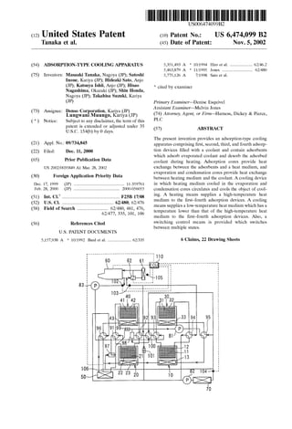
  • 1. USOO6474099B2 (12) United States Patent (10) Patent No.: US 6,474,099 B2 Tanaka et al. (45) Date of Patent: Nov. 5, 2002 (54) ADSORPTION-TYPE COOLING APPARATUS 5,351,493 A * 10/1994 Hiro et al. ................... 62/46.2 5,463.879 A 11/1995 Jones .......................... 62/480 (75) Inventors: Masaaki Tanaka, Nagoya (JP); Satoshi Inoue, Kariya (JP); Hideaki Sato, Anjo (JP); Katsuya Ishii, Anjo (JP); Hisao Nagashima, Okazaki (JP); Shin Honda, Nagoya (JP); Takahisa Suzuki, Kariya (JP) (73) Assignee: Denso Corporation, Kariya (JP) (*) Notice: Subject to any disclaimer, the term ofthis patent is extended or adjusted under 35 U.S.C. 154(b) by 0 days. (21) Appl. No.: 09/734,845 (22) Filed: Dec. 11, 2000 (65) Prior Publication Data US 2002/003.5849 A1 Mar. 28, 2002 (30) Foreign Application Priority Data Dec. 17, 1999 (JP) ........................................... 11-359761 Feb. 28, 2000 (JP) ....................................... 2OOO-056055 (51) Int. Cl." ................................................. F25B 17/08 (52) U.S. Cl. ............................................ 62/480; 62/476 (58) Field of Search .......................... 62/480, 481,476, 62/477, 335, 101, 106 (56) References Cited U.S. PATENT DOCUMENTS 5,157,938 A * 10/1992 Bard et al..................... 62/335 5 5.Af.1987 to | 5,775,126 A 7/1998 Sato et al. * cited by examiner Primary Examiner Denise Esquivel ASSistant Examiner Melvin Jones (74) Attorney, Agent, or Firm-Harness, Dickey & Pierce, PLC (57) ABSTRACT The present invention provides an adsorption-type cooling apparatus comprising first, Second, third, and fourth adsorp tion devices filled with a coolant and contain adsorbents which adsorb evaporated coolant and desorb the adsorbed coolant during heating. Adsorption cores provide heat eXchange between the adsorbents and a heat medium, and evaporation and condensation cores provide heat eXchange between heating medium and the coolant. A cooling device in which heating medium cooled in the evaporation and condensation cores circulates and cools the object of cool ing. A heating means Supplies a high-temperature heat medium to the first-fourth adsorption devices. A cooling means Supplies a low-temperature heat medium which has a temperature lower than that of the high-temperature heat medium to the first-fourth adsorption devices. Also, a Switching control means is provided which Switches between multiple States. 6 Claims, 22 Drawing Sheets 93 it Also, ( Lungwani (JP)KariyaMuungo,
  • 2. U.S. Patent Nov.5, 2002 Sheet 1 of22 US 6,474,099 B2 94 NDs J.E.E.SSSS S5.N Aft
  • 3. U.S. Patent Nov.5, 2002 Sheet 2 of 22 US 6,474,099 B2 FG. 2 HIGH-TEMPERATURE HEAT MEDIUM LOW-TEMPERATURE HEAT MEDIUM - - - - -COOLING WATER
  • 4. U.S. Patent Nov.5, 2002 Sheet 3 of 22 US 6,474,099 B2 FIG. 3 HIGH-TEMPERATURE HEAT MEDIUM LOW-TEMPERATURE HEAT MEDIUM - - - - -COOLING WATER
  • 5. U.S. Patent Nov. 5, 2002 Sheet 4 of22 US 6,474,099 B2 FIG. 4 HIGH-TEMPERATURE HEAT MEDIUM LOW-TEMPERATURE HEAT MEDIUM c - - -COOLING WATER
  • 6. US 6,474,099 B2Sheet 5 of 22Nov. 5, 2002U.S. Patent FIG. 5 -TEMPERATURE HEAT MEDIUM - - - - -COOLING WATER
  • 7. U.S. Patent Nov. 5, 2002 Sheet 6 of22 US 6,474,099 B2 F.G. 6 HIGH-TEMPERATURE HEAT MEDIUM LOW-TEMPERATURE HEAT MEDIUM COOLING WATER
  • 8. US 6,474,099 B2Sheet 7 of 22Nov.5, 2002U.S. Patent FIG. 7 HEAT MEDIUM LOW-TEMPERATURE HEAT MEDIUM - - - - -COOLING WATER
  • 9. US 6,474,099 B2Sheet 8 of 22Nov. 5, 2002U.S. Patent FIG. 8 HEAT MEDIUM - - - - -COOLING WATER
  • 10. U.S. Patent Nov.5, 2002 Sheet 9 of 22 US 6,474,099 B2 FIG. 9 HIGH-TEMPERATURE HEAT MEDIUM LOW-TEMPERATURE HEAT MEDIUM - - - - -COOLING WATER
  • 11.
  • 12. US 6,474,099 B2Sheet 11 of 22Nov.5, 2002U.S. Patent
  • 13. US 6,474,099 B2Sheet 12 of 22Nov.5, 2002 (JEJWM0NIT000––––– U.S. Patent
  • 14. US 6,474,099 B2Sheet 13 of 22Nov.5, 2002U.S. Patent }}|B|WM9NIT000-----
  • 15. US 6,474,099 B2Sheet 14 of 22Nov.5, 2002U.S. Patent }|E||WMONIT000----- O N.
  • 16. £8 US 6,474,099 B2Sheet 15 of 22Nov.5, 2002 83||WM0NIT000------–— U.S. Patent
  • 17. US 6,474,099 B2Sheet 16 of 22Nov.5, 2002U.S. Patent
  • 18. US 6,474,099 B2Sheet 17 of 22Nov.5, 2002U.S. Patent ------------ c O CN CN CO
  • 19. US 6,474,099 B2Sheet 18 of 22Nov.5, 2002U.S. Patent
  • 20. £8 US 6,474,099 B2Sheet 19 of 22Nov.5, 2002 83||WM0NIT000-------- U.S. Patent
  • 21.
  • 22.
  • 23. U.S. Patent Nov.5, 2002 Sheet 22 of 22 US 6,474,099 B2 FIG. 22A FIG. 22B DURING PRIOR TOSWITCHING SWITCHING 81-83 2. al d b (EX: - -/ aaraaaaaaara |91-101,2011-206 10,203040 | 91-101,201a2O6 AFTER SWITCHING FIG. 22C 2 d b |91a101, 201-206 FIG. 23 91a101, 2011-206
  • 24. US 6,474,099 B2 1 ADSORPTION-TYPE COOLING APPARATUS CROSS REFERENCE TO RELATED ART The present invention is related to Japanese patent appli cation No. Hei. 11-359761, filed Dec. 17, 1999; 2000-56055, filed Feb. 28, 2000; the contents of which are incorporated herein by reference. FIELD OF THE INVENTION The present invention relates to an adsorption-type cool ing apparatus, and more particularly to an adsorption-type cooling apparatus that is Suitable for application to air conditioners. BACKGROUND OF THE INVENTION The assignee has filed an application relating to an adsorption-type cooling apparatus containing at least four adsorption devices (Laid-open Japanese Patent Application 9-303900 hereby incorporated by reference). However, in the above-mentioned openly described invention, the appa ratus is difficult to control. SUMMARY OF THE INVENTION In View of the above, the present invention provides an adsorption-type cooling apparatus containing four adsorp tion devices. The present invention provides an adsorption type cooling apparatus comprising first, Second, third, and fourth adsorption devices. These devices are filled with a coolant and contain adsorbents which adsorb evaporated coolant and desorb the adsorbed coolant during heating. Adsorption cores provide heat eXchange between the adsor bents and a heat medium, and evaporation and condensation cores provide heat eXchange between heating medium and the coolant. A cooling device in which heating medium cooled in the evaporation and condensation cores circulates and cools the object of cooling. A heating means Supplies a high-temperature heat medium to the first-fourth adsorption devices. A cooling means Supplies a low-temperature heat medium which has a temperature lower than that of the high-temperature heat medium to the first-fourth adsorption devices. Also, a Switching control means is provided which Switches between multiple States. In a first State, a heat medium iscirculatedbetween the coolingdevice andevapo ration andcondensation cores ofthe first andSecond adsorp tion devices. The low-temperature heat medium iscirculated to the adsorption core of the first adsorption device and heating medium exiting the cooling device is circulated to the adsorption core of the Second adsorption device. Meanwhile, the high-temperature heat medium is circulated to the adsorption cores of the third and fourth adsorption devices and the low-temperature heat medium is circulated to the evaporation and condensation cores of the third and fourth adsorption devices. In a Second State, a heat medium is circulatedbetween the coolingdevice andevaporation and condensation cores of the first and Second adsorption devices and the low-temperature heat medium is circulated to the adsorption cores of the first and Second adsorption devices. Meanwhile the high-temperature heat medium is circulated to the adsorption cores of the third and fourth adsorption devices and the low-temperature heat medium is circulated to the evaporation and condensation cores of the third and fourth adsorption devices. In a third state, the low-temperature heat medium is Supplied to the inlet open ings of evaporation and condensation cores of the first and 15 25 35 40 45 50 55 60 65 2 Second adsorption devices and the high-temperature heat medium is Supplied to inlet openings ofthe adsorption cores of the first and second adsorption devices. Meanwhile, the low-temperature heat medium is Supplied to the inlet open ings of the adsorption cores of the third and fourth adsorp tion devices and heating medium exiting the cooling device is Supplied to the evaporation and condensation cores of the third and fourth adsorption devices. In a fourth state, the low-temperature heat medium is circulated to the evapora tion and condensation cores of the first and Second adsorp tion devices and the high-temperature heat medium is cir culated to the adsorption cores of the first and Second adsorption devices. Meanwhile, the low-temperature heat medium is circulated to the adsorption cores ofthe third and fourth adsorption devices and when the evaporation and condensation cores of the third and fourth adsorption devices were filled with heating medium that exited the cooling device, the circulation of this heat medium is terminated. In a fifth State, a heat medium is circulated between the cooling device and evaporation and condensa tion cores of the third and fourth adsorption devices, the low-temperature heat medium is circulated to the adsorption core of the third adsorption device, and heating medium exiting the cooling device iscirculatedto the adsorption core of the fourth adsorption device. Meanwhile, the high temperature heat medium is circulated to the adsorption cores of the first and Second adsorption devices and the low-temperature heat medium is circulated to the evapora tion and condensation cores of the first and Second adsorp tion devices. In a sixth State (VI), a heat medium is circu lated between the cooling device and evaporation and condensation cores of the third and fourth adsorption devices and the low-temperature heat medium is circulated to the adsorption cores of the third and fourth adsorption device. Meanwhile, the high-temperature heat medium is circulated to the adsorption cores of the first and Second adsorption devices and the low-temperature heat medium is circulated to the evaporation and condensation cores of the first and Second adsorption devices. In a Seventh State (VII), the low-temperature heat medium is Supplied to evaporation and condensation cores of the third and fourth adsorption devicesand the high-temperature heat medium isSupplied to the inlet openings ofadsorption cores ofthe third and fourth adsorption device. Meanwhile, low-temperature heat medium is Supplied to the inlet openings of the adsorption cores ofthe first and Second adsorption devices and heating medium exiting the cooling device is Supplied to the evapo ration andcondensation cores ofthe first andSecond adsorp tion devices. In an eighth state (VIII), the low-temperature heat medium is circulated to the evaporation and conden sation cores of the third and fourth adsorption devices and the high-temperature heat medium is circulated to the adsorption cores of the third and fourth adsorption device. Meanwhile, the low-temperature heat medium is circulated to the adsorption cores of the first and Second adsorption devices and when the evaporation and condensation cores of the first and second adsorption devices were filled with heating medium, exiting the cooling device, circulation of this heat medium is terminated. Accordingly, the Switching control means has a first Switching control pattern in which the States are Switched in the following order: first State (I)->second state (II)->third state (III)->fourth state (IV) ->fifth state (V)->sixth state (VI)->seventh state (VII) ->eighth state (VIII)->first state (I). AS a result, heating medium flowing out of the cooling device which was cooling the adsorption cores in the first and fifth States is Supplied to the evaporation and conden
  • 25. US 6,474,099 B2 3 sation cores undergoing the adsorption process, without being Supplied to the adsorption cores, in the Second and Sixth States. For this reason, the Supply of heating medium that has been heated while cooling the adsorption cores to the evaporation and condensation cores undergoing the adsorption proceSS in the next stage can be prevented. Therefore, heating of the evaporation and condensation cores undergoing the adsorption process in the next stage can be prevented in advance. As a result, it is possible to prevent the loSS of cooling capacity of the adsorption-type cooling apparatus. Also, the outflow temperature fluctuation is reducedby two-stage adsorption devices. Moreover, water hammering is prevented by Switching valves. In another aspect, the Switching control means has a Second Switching control pattern in which the States are switched in the following order: fourth state (IV)->seventh state (VII)->eighth state (VIII)->third state (III)->fourth state (IV). AS a result, if the Second control pattern is implemented when a large cooling capacity is required, the cooling capacity of two adsorption devices can be taken out of the cooling device and the coefficient of performance of the adsorption-type cooling apparatus can be increased. In another aspect, the Switching control means Switches the states in the following order: first state (I)->third state (III)->fourth state (IV)->fifth state (V)->seventh state (VII) ->eighthstate(VIII)->firststate(I),whentheoperationtime of said first and fifth states (I, V) is extended. AS a result, if the first and fifth States are extended, the caloric value of adsorbents located inside the adsorption devices is decreased. For this reason, the transition from the first state to the fifth state or the transition from the fifth state to the first State can be rapidly conducted. Without imple menting the Second and Sixth States. Therefore, the time period in which the adsorption-type cooling apparatus dem onstrates cooling capacity can be extended which increases the efficiency of the adsorption-type cooling apparatus. In another aspect, the flow rate of heating medium Sup plied to the evaporation and condensation cores in the third state (III) orseventh state (VII) isgreater than the flow rate ofheating medium Supplied to the evaporation and conden sation cores in the first state (I) or fifth state (V). As a result, the operation time of the third state (III) or seventh state (VII) can be shortened. Therefore, the time period during which the adsorption-type cooling apparatus demonstrates cooling capacity can be extended, and the cooling efficiency and coefficient of performance of the adsorption-type cooling apparatus can be increased. In another aspect, the Switching control means controls heating medium flow by controlling the valves Switching heating medium and flow pumps circulating heating medium flow. When the valves are switched, the Switching control means controls the pumps to terminate the circula tion of heating medium to the Switched valves. As a result, the action of a large force created by water impact (water hammer) on valves when the valves are Switched is pre vented. In another aspect, a check valve is installed inside heating medium channel through which heating medium flows, in a position in which heating medium flows in one direction only. As a result, the backward flow ofheating medium that was pushed in by the pump preSSure can be prevented even when the pumps are stopped. Therefore, the replacement of heat medium can be conducted quickly and accurately and the adsorption-type cooling apparatus can demonstrate its capacity in full. 15 25 35 40 45 50 55 60 65 4 Further areas ofapplicability ofthe present invention will become apparent from the detailed description provided hereinafter. Itshouldbe understood that the detailed descrip tion and Specific examples, while indicating preferred embodiments of the invention, are intended for purposes of illustration only, Since various changes and modifications within the spirit and scope of the invention will become apparent to those skilled in the art from this detailed descrip tion. Further areas of applicability of the present invention willbecome apparent from the detailed description provided hereinafter. Itshouldbe understood that the detailed descrip tion and Specific examples, while indicating preferred embodiments of the invention, are intended for purposes of illustration only, Since various changes and modifications within the spirit and scope of the invention will become apparent to those skilled in the art from this detailed descrip tion. In the drawings: BRIEF DESCRIPTION OF THE DRAWINGS The present invention will become more fully understood from the detailed description and the accompanying drawings, wherein: FIG. 1 is a Schematic view of the adsorption-type cooling apparatus of a first embodiment of the present invention; FIG. 2 is a schematic view showing the first state of the adsorption-type cooling apparatus of Embodiment 1 of the present invention; FIG. 3 isa schematic view showingthe secondstate ofthe adsorption-type cooling apparatus of Embodiment 1 of the present invention; FIG. 4 is a schematic view showing a third state of the adsorption-type cooling apparatus of Embodiment 1 of the present invention; FIG. 5 is a schematic view showing a fourth state of the adsorption-type cooling apparatus of Embodiment 1 of the present invention; FIG. 6 is a schematic view showing a fifth state of the adsorption-type cooling apparatus of Embodiment 1 of the present invention; FIG. 7 is a schematic view showing a sixth state of the adsorption-type cooling apparatus of Embodiment 1 of the present invention; FIG. 8 is a schematic view showing a seventh state of the adsorption-type cooling apparatus of Embodiment 1 of the present invention; FIG. 9 is a schematic view showing an eighth state of the adsorption-type cooling apparatus of Embodiment 1 of the present invention; FIG. 10 is a chart showing the operation of the selector Valves and first pump of the adsorption-type cooling appa ratus of Embodiment 1 of the present invention; FIG. 11 is aSchematic view ofthe adsorption-type cooling apparatus of Embodiment 6 of the present invention; FIG. 12 is a schematic view showing a first state of the adsorption-type cooling apparatus of Embodiment 6 of the present invention; FIG. 13 is a schematic view showing a second state ofthe adsorption-type cooling apparatus of Embodiment 6 of the present invention; FIG. 14 is a schematic view showing a third state of the adsorption-type cooling apparatus of Embodiment 6 of the present invention; FIG. 15 is a schematic view showing a fourth state of the adsorption-type cooling apparatus of Embodiment 6 of the present invention;
  • 26. US 6,474,099 B2 S FIG. 16 is a schematic view showing a fifth state of the adsorption-type cooling apparatus of Embodiment 6 of the present invention; FIG. 17 is a schematic view showing a sixth state of the adsorption-type cooling apparatus of Embodiment 6 of the present invention; FIG. 18 is a schematic view showinga seventh state ofthe adsorption-type cooling apparatus of Embodiment 6 of the present invention; FIG. 19 is a schematic view showing an eighth state ofthe adsorption-type cooling apparatus of Embodiment 6 of the present invention; FIG. 20 is a graphical view showing the operation of the Selector valvesandfirst pump ofthe adsorption-type cooling apparatus of Embodiment 6 of according to the present invention; FIG. 21 is a graphical view showing the operation of the Selector valves and pumps of the adsorption-type cooling apparatus of Embodiment 7 of the present invention; FIG.22 is a schematic view showing the operation of the Selector valves and pumps of the adsorption-type cooling apparatus of the present invention; and FIG. 23 is a schematic view showing the check valve installed in the adsorption-type cooling apparatus of Embodiment 8 of the present invention. In a first embodiment, as shown in FIG. 1, the adsorption type cooling apparatus is applied to an air conditioner for vehicles. In this figure, reference symbols 10, 20, 30, 40 stand for first-fourth adsorption devices. These adsorption devices 10, 20, 30, 40 are filled with a coolant (in this embodiment, water) and contain adsorbents 11, 21, 31, 41, Such as Silica gel and the like, which adsorb evaporated coolant and desorb the adsorbed coolant during heating. Adsorption cores 12,22,32,42 are adhesively bonded to the surface to the adsorbents 11, 21, 31, 41, and provide heat exchange between the adsorbents 11, 21, 31, 41 and a heat medium (in this embodiment, water mixed with an ethylene glycol-based antifreeze; identical to engine cooling water). Evaporation and condensation cores 13, 23, 33, 43 provide heat eXchange between heating medium and coolant. The inside of the first-fourth adsorption devices 10,20,30, 40 is maintained almost under vacuum. Internal heat exchanger 50 (cooling device), in which heating medium cooled in the evaporation and condensation cores 13, 23, 33, 43 circulates, cools the air (object of cooling)blown outinto the compartment.Adsorbents 11,21, 31,41 are heated with the waste heat(enginecoolingwater) of engine 60 as a heat Source. An external heat exchanger (cooling means) 70 provides heat eXchange between heating medium and outside air and Supplies heating medium, having a temperature lower than that of the engine cooling water, (high-temperature heat medium) to first-fourth adsorption devices 10, 20, 30, 40. First-third electric pumps 81-83 circulate heating medium (including engine cooling water) between the first-fourth adsorption devices 10, 20, 30, 40, internal heat exchanger 50, external heat exchanger 60 (sic), and engine 60. Electric selector valves 91-101 Switch heating medium flow. Valves 91–96, 100 are four-way valves, valves 97, 98 are three-way valves, and the valves 99, 100 are two-way valves. A first water temperature sensor 102 (first temperature detection means) detects the temperature ofheating medium flowing out of engine 60 and to the first-fourth adsorption devices 10, 20, 30, 40. A second water temperature sensor 15 25 35 40 45 50 55 60 65 6 103 (second temperature detection means) detects the tem perature ofheating medium returning to engine 60 from the first-fourth adsorption devices 10, 20, 30, 40. A third water temperature Sensor 104 (third temperature detection means) detects the temperature of heating medium flowing out of the external heat exchanger 70. A radiator 61 cools the engine cooling water, and a thermostat 62 maintains the temperature of the engine cooling water at the prescribed level (80–110° C) by adjustingthe rate offlow passingthrough the radiator 61.An outside air sensor 105 (outside air temperature detection means) detects the external air temperature, an inflow air temperature sensor 106 (inflow air temperature detection means) detects the temperature of the air flowing into the internal heat exchanger 50, the detected values of these sensors 102-106 are input to an electronic control unit (ECU) 110. The ECU 110 (Switching control means) controls the first-third pumps 81-83 and selector valves 91-101 accord ing to the preset program based on the detected values of Sensors 102-106. The base operation States of the air conditioner for vehicles (adsorption-type cooling apparatus) of the present embodiment will be described below. 1. First State (I) In the first State, as shown in FIG. 2, heating medium is circulated between the internal heat exchanger 50 and evaporation and condensation cores 13, 23 of the first and second adsorption devices 10,20. The low-temperature heat medium (heat medium cooledin the external heatexchanger 70) iscirculated to adsorption core 12 ofthe first adsorption device 10, and heating medium exiting the internal heat exchanger 50 is circulated to adsorption core 22 of the Second adsorption device 20. Meanwhile, the high temperature heat medium (engine cooling water exiting engine 60) is circulated to adsorption cores 32, 42 of the third and fourth adsorption devices 30, 40 and the low temperature heat medium is circulated to evaporation and condensation cores 33, 43 of the third and fourth adsorption devices 30, 40. 2. Second State (II) In the Second State, as shown in FIG. 3, heating medium is circulated between the internal heat exchanger 50 and evaporation and condensation cores 13, 23 of the first and second adsorption devices 10, 20 and the low-temperature heat medium is circulated to adsorption cores 12, 22 of the first and second adsorption devices 10, 20. Meanwhile, the high-temperature heat medium is circulated to adsorption cores32, 42 ofthe third andfourth adsorption devices30,40 and the low-temperature heat medium iscirculated toevapo ration and condensation cores 33, 43 ofthe third and fourth adsorption devices 30, 40. Third State (III) In the third state, asshown in FIG. 4, the low-temperature heat medium is Supplied to evaporation and condensation cores 13, 23 ofthe firstand second adsorption devices 10,20 and the high-temperature heat medium is Supplied to the inlet openings of adsorption cores 12, 22 of the first and second adsorption devices 10, 20. Meanwhile, the low temperature heat medium is Supplied into the inlet openings of adsorption cores 32, 42 of the third and fourth adsorption devices30, 40 and heating medium exiting the internal heat eXchanger50 isSuppliedto the inletopeningsofevaporation and condensation cores 33, 43 of the third and fourth adsorption devices 30, 40. Fourth State (VI) In the fourth state, as shown in FIG. 5, the low temperature heat medium is circulated to evaporation and
  • 27. US 6,474,099 B2 7 condensation cores 13, 23 ofthe first and Second adsorption devices 10, 20 and the high-temperature heat medium is circulated to the adsorption cores 12, 22 of the first and second adsorption devices 10, 20. Meanwhile, the low temperature heat medium is circulated to the adsorption cores 32, 42 of the third and fourth adsorption devices 30, 40. when the evaporation and condensation cores 33, 43 of the third and fourth adsorption devices 30, 40 are filled with heating medium exiting internal heat eXchanger 50, the first pump 81 is Stopped and the circulation of heating medium in the evaporation and condensation cores 33, 43 is termi nated. Fifth State (V) In the fifth state, as shown in FIG. 6, heating medium is circulated between the internal heat exchanger 50 and evaporation and condensation cores 33, 43 of the third and fourth adsorption devices 30, 40. The low-temperature heat medium is circulated to the adsorption core 32 of the third adsorption device 30, and heating medium exiting the inter nal heat exchanger 50 is circulated to adsorption core 43 of the fourth adsorption device 40. Meanwhile, the high temperature heat medium is circulated to adsorption cores 12,22 of the first and second adsorption devices 10, 20 and the low-temperature heat medium is circulated to evapora tion and condensation cores 13, 23 of the first and second adsorption devices 10, 20. Sixth State (VI) In the sixth state, as shown in FIG. 7, heating medium is circulated between the internal heat exchanger 50 and evaporation and condensation cores 33, 43 of the third and fourth adsorption devices 30, 40. The low-temperature heat medium is circulated to the adsorption cores 32, 42 of the third and fourth adsorption device 30, 40. Meanwhile, the high-temperature heat medium is circulated to adsorption cores 12, 22 ofthe firstand second adsorption devices 10,20 and the low-temperature heat medium iscirculated to evapo ration and condensation cores 13, 43 (sic) of the first and second adsorption devices 10, 20. Seventh State (VII) In the seventh state, as shown in FIG. 8, the low temperature heat medium is Supplied to the inlet openings of evaporation and condensation cores 33, 43 of the third and fourth adsorption devices30, 40. The high-temperature heat medium is Supplied to the inlet openings of adsorption cores 32, 42 of the third and fourth adsorption device 30, 40. Meanwhile the low-temperature heat medium is Supplied to adsorption cores 12, 22 of the first and Second adsorption devices 10,20 and heating medium exiting the internal heat eXchanger50 isSupplied to the inlet openings ofevaporation and condensation cores 13, 23 of the first and second adsorption devices 10, 20. Eighth State (VIII) In the eighth state, as shown in FIG. 9, the low temperature heat medium is circulated to evaporation and condensation cores 33, 43 of the third and fourth adsorption devices 30, 40. The high-temperature heat medium is cir culated to the adsorption cores 32, 42 ofthe third and fourth adsorption device 30, 40. Meanwhile, the low-temperature heat medium is circulated to adsorption cores 12, 22 of the first and second adsorption devices 10, 20 and when the evaporation and condensation cores 13, 23 of the first and second adsorption devices 10, 20 are filled with heating mediumexitinginternal heatexchanger50,the first pump81 is stopped and the circulation of heating medium in the evaporation and condensation cores 13, 23 is terminated. FIG. 10 is a diagram illustrating the operation of selector valves 91-101 and first pump 81. Here, the operation time 15 25 35 40 45 50 55 60 65 8 of the first and fifth states was selected based on the time required for the water(evaporated coolant) adsorption abil ity tobe Saturated.This time variesdependingon the relative humidity range inside the adsorption devices during adsorp tion operation or the type and amount of the adsorbent. The operation of the present embodiment will be described below based on the aforesaid first-eight states. 1. Normal Operation Mode In the normal operation mode, a first Switching control pattern is realized in which the States are Switched in the following order: firststate (I)->secondstate (II)->third state (III)->fourth state (IV)->fifth state (V)->sixth state (VI) ->seventh state (VII)->eighth state (VIII)->first state (I). Here,the operation time ofthe thirdstate (III)andseventh state (VII) is referred to as the time required to replace the low-temperature heat medium present inside the evaporation and condensation cores of the adsorption devices that have been in the desorption process with heating medium exiting the internal heat exchanger 50. This time is determined by the yield of the first pump 81 and the volume of heating medium channel inside evaporation and condensation cores 13, 23 or 33, 43. In the desorption process, the adsorbed coolant is des orbed and discharged by Supplying a high-temperature heat medium to the adsorption cores, having adsorbent that adsorbed coolant, and heating the adsorbent. More specifically, the third and fourth adsorption devices30,40 in the first-fourth States and the first and Second adsorption devices 10, 20 in the fifth-seventh states are in the desorp tion process. Thereupon, in the normal operation mode, air flowing out into the compartment in the first-third states and fifth-sev enth States iscooled. However, in the first and fifth State, the adsorbent is cooled by heating medium flowing out of the internal heat exchanger 50. Therefore, in the first state, the cooling capacity of cooling air flowing out into the com partment is the cooling capacity generated in the first adsorption device 1. In the fifth State, it is the cooling capacity generated by the third adsorption device 30. In the adsorption process, the liquid-phase coolantpresent inside the adsorption devices is evaporated and the evapo rated vapor (gas-phase) coolant is adsorbed by the adsor bent. The cooling capacity in the adsorption device, under going the adsorption process, is demonstrated owing to the latent heat of evaporation of the coolant. In this connection, the Second adsorption device 20 in the first state and the fourth adsorption device 40 in the fifth State decrease the temperature of heating medium cooled in the first adsorption device 10 and third adsorption device 30 to a temperature that enables heat eXchange with the internal air and does not increase the heat removed from the air blown out into the compartment. 2. High-load Operation Mode The high-load operation mode is a mode implemented when the temperature (detected temperature of inflow air temperature sensor 106) of the air flowing into the internal heat exchanger 50 is no less than about 40 C. and the thermal load required in the internal heat exchanger 50 is high. In this mode, a Second Switching control pattern is realized comprising Switching the States in the following order: fourth state (IV)->seventh state (VII)->eighth state (VIII)->third state (III)->fourth state (IV). Thereupon, in the high-load operation mode, cooling of the adsorbent of the adsorption devices in the adsorption process by heating medium flowing out of the internal heat exchanger50 is avoided by omitting the first and fifth states. AS a result, almost the entire cooling capacity generated in
  • 28. US 6,474,099 B2 9 the two adsorption devices which are in the adsorption proceSS can contribute to the cooling of the air blown out into the compartment and can correspond to a high thermal load. Furthermore, in a high-load operation mode, the adsor bent of the adsorption devices, not undergoing the adsorp tion process, are not cooled by heating medium flowing out ofthe internal heatexchanger50.Therefore,the temperature of the air blown out into the compartment cannot be decreased to the same degree as in the normal operation mode. However, as described above, Since almost the entire cooling capacity generated by the two adsorption devices which are in the adsorption process cancontribute to cooling of the air blown out into the compartment, the coefficient of performance ofthe adsorption-type coolingapparatuscanbe increased and the waste heat ofengine 60 can be effectively utilized. The coefficient of performance of the adsorption-type cooling apparatus in this case is the value obtained by dividing the amount of heat removed from the air blown out into the compartment by the amount of heat Supplied from engine 60. 3. Low-load Operation Mode The low-load operation mode is a mode implemented when the temperature ofthe air flowing into the internalheat exchanger 50 is not lower than about 22 C. and not higher than27 C., and the thermal load requiredin the internal heat exchanger 50 is small. More specifically, in this mode, Similar to the high-load operation mode, a Second Switching control pattern is realized comprisingSwitching the States in the following order: fourth state (IV)->seventh state (VII) ->eighth state (VIII) ->third state (III)->fourth state (IV). As a result, Similar to the high-load operation mode, though the temperature of the air flowing into the internal heat eXchanger 50 cannot be largely decreased, Since the temperature of the air flowing into the internal heat exchanger 50 is low, the coefficient of performance of the adsorption-type cooling apparatus can be increased while the temperature ofthe air blown out into the compartment is lowered to a level Sufficient for practical purposes. 4. Extended Operation Mode The extended operation mode is a mode implemented when the operation time of the first and fifth states is extended from the initial set time (see FIG. 10). More Specifically, a third Switching control pattern is realized that comprises Switching the States in the following order: first state (I)->third state (III)->fourth state (IV)->fifth state (V)->seventhstate(VII)->eighth state(VIII)->firststate(I). In the extended operation mode, the Second and Sixth States are omitted. Therefore, for example, in a transition from the first State to the third and fourth States, heating medium that has entered the adsorption core 22 during the adsorption process (in the first State) flows as is in evapo ration and condensation cores 33, 43 of the adsorption devices 30, 40 which are subsequently in the adsorption process. It is possible that the evaporation and condensation cores33,43 will be heatedby heating medium heated by the adsorption core 22. However, when the operation time of the first and fifth States is extended from the initial Set time, the water adsorp tion capacity (amount ofadsorbed water) ofthe adsorbent is decreased and the heat of adsorption which is generated during water adsorption is decreased. Therefore, even though heating medium that has entered the adsorption core during the adsorption process flows as in the evaporation and condensation cores of the adsorption devices, it causes no practical problems. 15 25 35 40 45 50 55 60 65 10 Furthermore, in the extended operation mode of the present embodiment, the operation time ofthe first and fifth states is extended from the initial set time till the difference between the temperature (detected temperature of the first watertemperature sensor 102) ofthe supplied heat medium which flows out of engine 60 and into the first-fourth adsorption devices 10, 20, 30, 40 and the temperature (detected temperature ofthe Second water temperature Sen sor 103) ofthe outflow heat medium which returns from the first-fourth adsorption devices 10, 20, 30, 40 to engine 60 becomes the preset temperature difference. Herein, the prescribed temperature difference is referred to a state with a temperature difference ofabout 0°C., more specifically, ofno less than 1 C. and no more than about 5 C. Specific features of the present embodiment will be described below. The heat medium flowing out of the internal heat exchanger 50 which cooled the adsorption cores in the first and fifth States is Supplied to the evaporation and conden sation cores undergoing the adsorption process, without being Supplied to the adsorption cores, in the Second and Sixth States. For this reason, the Supply of heating medium, heatedwhile coolingthe adsorptioncores, to the evaporation and condensation cores undergoingthe adsorption proceSS in the next stage can be prevented. Therefore, heating of the evaporation and condensation cores undergoing the adsorption process in the next stage can be prevented in advance. As a result, it is possible to prevent the loSS of cooling capacity of the adsorption-type cooling apparatus (air conditioner) in the normal operation mode, high-load operation mode, and low-mode operation mode. Furthermore, in the third and seventh states, heating medium exiting internal heateXchanger 50 is Supplied to the evaporation and condensation cores undergoing the adsorp tion proceSS in the next stage. For this reason, it is possible to discharge the low-temperature heat medium which flows out of external heat eXchanger 70 having a temperature higherthan thatofheating medium circulating in the internal heat eXchanger 50. Therefore, the evaporation and conden sation cores undergoing the adsorption proceSS in the next Stage can be cooled which makes it possible to prevent the loSS of cooling capacity of the adsorption-type cooling apparatus (air conditioner) in the normal operation mode, high-load operation mode, low-mode operation mode, and extended operation mode. Furthermore, Since in the extended operation mode a transition is made to the third and seventh state without implementing the Second and Sixth States, the working process of the adsorption-type cooling apparatus can be shortened which makes itpossible to use effectively the heat Supplied from engine 60 as a heat Source (energy) driving the adsorption-type cooling apparatus and to increase the coefficient of performance of the adsorption-type cooling apparatuS. Furthermore, Since in the extended operation mode the operation time of the first and fifth states is extended from the initial set time until the difference between the tempera ture of the Supplied heat medium and the temperature of heating medium that flows out becomes the prescribed temperature difference, almost the entire amount of water adsorbed by the adsorbent can be desorbed and discharged. Therefore, the heat supplied from engine 60 can be effec tively used as a heat Source (energy) driving the adsorption type cooling apparatus, which makes it possible to increase the coefficient ofperformance ofthe adsorption-type cooling apparatuS.
  • 29. US 6,474,099 B2 11 Embodiment 2 In Embodiment 1, the flow rate of first pump 81 was almost constant regardless of the working State. In the Second embodiment, the flow rate of heating medium Sup plied to the evaporation and condensation cores in the third state (III) orseventhstate (VII) ismadehigher thanthe flow rate of heating medium Supplied to the evaporation and condensation cores in the first state (I) or fifth state (V). As a result, the operation time of the third state (III) or seventh state (VII) can be shorted, extending. the time period during which the adsorption-type cooling apparatus demonstrates cooling capacity and increasing the cooling capacity and coefficient of performance of the adsorption type cooling apparatus. Embodiment 3 In the extended operation mode of Embodiment 1, the operation time of the first and fifth states is extended from the initial set time until the difference between the tempera ture of the Supplied heat medium and the temperature of heating medium that flows out becomes the prescribed temperature difference. However, in the third embodiment, the operation time of the first and fifth states is extended from the initial Set time until the temperature ofthe Supplied heat medium becomes the prescribed temperature (for example, no less than 80° C. and no higher than 100° C.). During this time, the engine cooling water is controlled, as described above, So as to be maintained at the prescribed temperature. Therefore, extending the operation time of the first and fifth states from the initial set time until the temperature of the Supplied heat medium becomes the prescribed temperature is identical to extending the opera tion time of the first and fifth states from the initial set time until the difference between the temperature of the Supplied heat medium and the temperature of heating medium that flows out becomes the prescribed temperature difference. Embodiment 4 In the extended operation mode of Embodiment 1, the operation time of the first and fifth states is extended from the initial set time until the difference between the tempera ture of the Supplied heat medium and the temperature of heating medium that flows out becomes the prescribed temperature difference. However, in this embodiment, the operation time of the first and fifth states is extended from the initial Set time until the temperature of heating medium that flows out becomes the prescribed temperature (for example, no less than 80° C. and no higher than 90° C). During this time, the engine cooling water is controlled, as described above, So as to be maintained at the prescribed temperature. Therefore, extending the operation time of the first and fifth states from the initial set time until the temperature of heating medium that flows out becomes the prescribed temperature is identical to extending the opera tion time of the first and fifth states from the initial set time until the difference between the temperature of the Supplied heat medium and the temperature of heating medium that flows out becomes the prescribed temperature difference. Embodiment 5 In the above-described embodiments, the operation time ofthe first and fifth stateswasbased on the water adsorption capacity ofthe adsorbent. However, in the fifth embodiment, the operation State (caloric value) of engine 60 is detected and the operation time ofthe first and fifth states is variably controlled based on the detected values. 15 25 35 40 45 50 55 60 65 12 Furthermore, when the operation state (caloric value) of engine 60 is detected, it is desired that the Setting be made based, for example, on the temperature of engine cooling water or the amount of fuel (injected amount of fuel) Supplied to the engine. Embodiment 6 In the above-described embodiments, the adsorption-type cooling apparatus was operated by using three-way and four-way valves for Switching heating medium flow. By contrast, in the present embodiment, the adsorption-type cooling apparatus was constructedby usingfour-way valves 201-204 and six-way valves 205, 206. FIG. 12 is a schematic view illustrating the first state (I), FIG. 13 isa schematic view illustratingthe secondstate(II), FIG. 14 is a schematic view illustrating the third state (III), FIG. 15isa schematic view illustratingthe fourth state (IV), FIG. 16 is a schematic view illustrating the fifth state (V), FIG. 17 is a schematic view illustrating the sixth state (VI), FIG. 18 is a schematic view illustrating the seventh state (VII), FIG. 19 is a schematic view illustrating the eighth state (VIII), FIG.20 isa time chart illustrating the operation of valves 201-206 and first pump 81. Embodiment 7 In this embodiment, when the valves 201-206 are Switched according to the operation time charts of Valves 201-206 and first-third pumps 81-83, which are shown in FIG. 21, the pumps circulating heating medium to the activated valves are Stopped only within the prescribed time periods before and after the Switching time. When the valves 201-206 are Switched, the valves 201-206 instantaneously get into an entirely closed State, as shown in FIG. 22. Therefore, there is a possibility that a Strong force generating an abnormal noise will act upon the valves 201-206 due to a water impact (water hammer) acting upon the valves201-206. Furthermore, in FIG. 22, a four-way valve is presented, but this figure is an example which does not indicate that only the four-way valve can be used. In this regard, in the present embodiment, the pumps circulating heating medium to the valves, which are Switched, are stopped. Therefore, the effect ofa strongforce created by the water impact (water hammer) on valves 201–206 is prevented. Furthermore, in FIG. 21, this embodiment was explained by referring to an adsorption-type cooling apparatus of Embodiment 6. However, the present invention is not lim ited thereto and can be applied to the adsorption-type cooling apparatus, for example, of Embodiment 1. Embodiment 8 In this embodiment, a check valve 207 is installed in the apparatus of Embodiment 7 inside heating medium channel through which heating medium flows, in a position in which heating medium flows in one direction only. Furthermore, in FIG. 23, a four-way valve is presented. However, this figure is anexample which does not indicate thatonly the four-way Valve can be used. Incidentally, in Embodiment 7, the pumps 81-83 are stopped when the valves 201-206 are Switched. Therefore, heating medium pushed in by the pump pressure may flow backward when the pumps 81-83 are stopped. If heating medium flowsbackward, the replacement ofheat medium is difficult to conduct quickly and accurately. Therefore, the capacity of the adsorption-type cooling apparatus may be decreased.
  • 30. US 6,474,099 B2 13 In this regard, because this embodiment employs the checkvalve 207,even ifthe pumps 81-83 are stopped when the selector valves 201-206 are Switched, heating medium that was pushed in by the pump pressure is prevented from flowing backward. Therefore, the replacement of heat medium can be conducted quickly and accurately. AS a result, the adsorption-type cooling apparatus can demon Strate its capacity in full. Furthermore, in FIG. 23, the check valve 207 was installed in the exit side of the selector valve. However, the present embodiment is not limited to this configuration, and the check valve can be in any position inside heating medium channel through which heating medium flows, provided that this is a position in which heating medium flows in one direction only. Other Embodiments In the above-described embodiments, the present inven tion was applied to an air conditioner for vehicles. However, the present invention is not limited to this application and can be applied to other cooling apparatus. Furthermore, a Silica gel was used as the adsorbent, but active alumina, active carbon, Zeolites, molecular Sieving carbon and the like may also be used. While the above-described embodiments refer to examples of usage of the present invention, it is understood that the present invention may be applied to other usage, modifications and variations of the same, and is not limited to the disclosure provided herein. While the above-described embodiments refer to examples of usage of the present invention, it is understood that the present invention may be applied to other usage, modifications and variations of the same, and is not limited to the disclosure provided herein. What is claimed is: 1. An adsorption-type cooling apparatus comprising: first, Second, third, and fourth adsorption devices, each of Said first, Second, third, and fourth adsorption devices are filled with a coolant and contain an adsorbent which adsorbSevaporated coolant and desorbs adsorbed cool ant duringheating, each ofSaid first, Second, third, and fourth adsorption devices having an adsorption core, each Said adsorption core providing heat eXchange between a respective Said adsorbent and a heating medium; evaporation and condensation cores providing heat eXchange between a heating medium and the coolant; a cooling device in which heating medium cooled in Said evaporation and condensation cores circulates and cools an object of cooling, heating meansSupplyinga high-temperature heat medium to Said first, Second, third and fourth adsorption devices, cooling means Supplying a low-temperature heat medium which has a temperature lower than that of Said high temperature heat medium to Saidfirst,Second, third and fourth adsorption devices, Switching control means which Switches between: a first State where a heating medium is circulated between Said cooling device and evaporation and condensation cores of Said first and Second adsorp tion devices, Said low-temperature heat medium is circulated to Said adsorption core ofSaid firstadsorp tion device, heating medium exiting Said cooling device is circulated to Said adsorption core of Said 15 25 35 40 45 50 55 60 65 14 Second adsorption device while Said high temperature heat medium is circulated to Said adsorption cores of Said third and fourth adsorption devices and Said low-temperature heat medium is circulated to the evaporation and condensation cores of Said third and fourth adsorption devices, a Second State in which a heat medium is circulated between Said cooling device and evaporation and condensation cores of Said first and Second adsorp tion devices, Said low-temperature heat medium is circulated to Said adsorption cores of Said first and Second adsorption devices while Said high temperature heat medium is circulated to Said adsorption cores of Said third and fourth adsorption devices and Said low-temperature heat medium is circulated to the evaporation and condensation cores of Said third and fourth adsorption devices, third State in which Said low-temperature heat medium is Supplied to the inlet openings of evapo ration and condensation cores ofSaid first and Second adsorption devices and Said high-temperature heat medium is Supplied to inlet openings ofSaid adsorp tion cores ofSaid first and Second adsorption devices while Said low-temperature heat medium is Supplied to the inlet openings of Said adsorption cores ofSaid third and fourth adsorption devices and heating medium exitingSaidcoolingdevice is Supplied to the evaporation and condensation cores ofSaid third and fourth adsorption devices, a fourth State where Said low-temperature heat medium is circulated to the evaporation and condensation cores ofSaid first and Second adsorption devices and Said high-temperature heat medium is circulated to Said adsorption cores ofSaid first andSecond adsorp tion devices while Said low-temperature heat medium is circulated to Said adsorption cores ofSaid third and fourth adsorption devices, wherein the circulation of this heat medium is terminated when Said evaporation andcondensation cores ofSaidthird and fourth adsorption devices were filled with heat ing medium exiting Said cooling device; a fifth state where a heat medium is circulated between Said cooling device and evaporation and condensa tioncores ofSaid third and fourth adsorption devices, Said low-temperature heat medium is circulated to Said adsorption core of Said third adsorption device and heating medium exiting Said cooling device is circulated to Said adsorption core of Said fourth adsorption device, wherein while Said high temperature heat medium is circulated to Said adsorption cores of Said first and Second adsorption devices and Said low-temperature heat medium is circulated to the evaporation and condensation cores of Said first and Second adsorption devices, a Sixth State in which a heat medium is circulated between Said cooling device and evaporation and condensation cores of Said third and fourth adsorp tion devices and Said low-temperature heat medium iscirculatedtoSaid adsorption cores ofSaid third and fourth adsorption device while Saidhigh-temperature heat medium is circulated to Said adsorption cores of Said first and Second adsorption devices and Said low-temperature heat medium is circulated to the evaporation and condensation cores ofSaid first and Second adsorption devices, a Seventh State in which said low-temperature heat medium is Supplied to evaporation and condensation
  • 31. US 6,474,099 B2 15 cores ofSaid third and fourth adsorption devices and Said high-temperature heat medium is Supplied to the inlet openings of adsorption cores of Said third and fourth adsorption device while Said low-temperature heat medium isSupplied to the inlet openings ofSaid adsorption cores of Said first and Second adsorption devices and heating medium exiting Said cooling device is Supplied to the evaporation and condensa tioncores ofSaid first andSecondadsorption devices, and an eighth State in which Said low-temperature heat medium is circulated to the evaporation and conden sation cores of Said third and fourth adsorption devices and Said high-temperature heat medium is circulated to Said adsorption cores of Said third and fourth adsorption device while Said low-temperature heat medium is circulated to Said adsorption cores of Said first and Second adsorption devices, wherein the circulation of this heat medium is terminated when the evaporation and condensation cores of Said first and Second adsorption devices were filled with heat ing medium exiting Said cooling device, and whereinSaidSwitchingcontrol meanshas a firstSwitch ingcontrolpattern in which the States are Switched in an order of the first State, Second State, third State, fourth State, fifth State, Sixth State, Seventh State, eighth State, first State. 2. The adsorption-type cooling apparatus according to claim 1, wherein Said Switching control means has a Second Switching control pattern in which the States are Switched in 15 25 16 the order of fourth State, Seventh State, eighth State, third State, fourth State. 3. The adsorption-type cooling apparatus according to claim 1, wherein Said Switching control means has a third Switching controlpattern in which the States are Switched in an order of the first State, third State, fourth State, fifth State, Seventh State, eighth State, first State, when the operation time of said first and fifth states is extended. 4. The adsorption-type cooling apparatus according to claims 1, wherein the flow rate of heating medium Supplied to Saidevaporation and condensation cores in Said third State or said Seventh State is greater than the flow rate of heating medium Suppliedto Said evaporation andcondensationcores in said first state or said fifth state. 5. The adsorption-type cooling apparatus according to claim 1, wherein Said Switching control means controls heating medium flow by controlling valves disposed along a flow of Said heating medium and by Switching heating medium and flow pumps circulating heating medium flow, and when Said valves are Switched, Said Switching control means controls Said pumps to terminate the circulation of heating medium to the Switched valves. 6. The adsorption-type cooling apparatus according to claim 5, wherein a check valve is installed inside heating medium channel through which heating medium flows, in a position in which heating medium flows in one direction only.