1. US 20130032033A1
(19) United States
(12) Patent Application Publication (10) Pub. No.: US 2013/0032033 A1
Bint et al. (43) Pub. Date: Feb. 7, 2013
(54) SYSTEM AND METHOD FOR ANALYSING (30) Foreign Application Priority Data
EXHAUST GAS
Nov. 6, 2009 (GB) ................................. .. 0919531.4
(75) Inventors: Wayne Anthony Bint, Eynsham (GB); . . . .
Daniel Kenneth Skelton, Godstone Pubhcatlon Classl?catlon
(GB); Timothy John Rogers, Biggm (51) Int CL
H111 (GB) B01D 39/20 (2006.01)
_ ~ _ _ B01D 46/42 (2006.01)
(73) Asslgnee' seratel L‘m‘ted’ Godstone’ Surrey (GB) (52) us. Cl. ....................................................... .. 96/417
(21) Appl. No.: 13/508,339 (57) ABSTRACT
_ _ A system for analysing exhaust gas, comprising: a sensor for
(22) PCT Flled' NOV‘ 8’ 2010 sensing a properly of exhaust gas: a conduit for transferring
(86) PCT NO _ PCT/GB2010/002050 exhaust gas from part ofan exhaust system to the sensor; and
" an inorganic ?lter element con?gured to remove particulates
§ 371 (c)(1), from exhaust gas between an end of the conduit and the
(2), (4) Date: Sep. 18, 2012 sensor. A method of analysing exhaust gas is also disclosed.
iliwm‘tmstkm
5. US 2013/0032033 A1
SYSTEM AND METHOD FOR ANALYSING
EXHAUST GAS
[0001] The present invention relates to systems and meth
ods for analysing exhaust gas.
[0002] There are many sources of exhaust gases from the
combustion offuel, such as motor vehicles, fumaces, boilers,
heal generators, electricity generators, poWer plants, etc.
These exhaust gases contain many different pollutants. These
pollutants include hydrocarbons (HC), carbon monoxide
(CO), nitrogen oxides (NOx), carbon dioxide (CO2), sulphur
oxides (SOX) and particulates. Some ofthese pollutants have
been demonstrated to have signi?cant effects on human, ani
mal, plant, and environmental health and Welfare. Thus many
government agencies around the World have been charged
With regulating exhaust emissions. The exhaust emissions
from vehicles are regularly tested and analysed to ensure the
vehicles meet emissions standards. The emissions from other
sources (such as those mentioned above) also need to be
controlled.
[0003] Gas analysers, Which are systems for analysing
exhaust gas are commonly used to measure the gaseous emis
sions from internal combustion engines. The gas analysers
can also be used to provide additional information on the
condition of an internal combustion engine. For example,
CO2, NO,C and oxygen (O2) readings can indicate the e?i
ciency of combustion in the combustion chamber of an
engine. The gas analysers can also be used to diagnose engine
running faults and the measure the performance of emission
control systems.
[0004] Current gas analysers are capable of measuring
around four or ?ve gases from exhaust emissions. Informa
tion about these four or ?ve gases are Widely used to deter
mine the condition of spark ignition engines. These generic
gas analysers are currently not used for compression ignition
engines because of dif?culties resulting from the high soot
content of exhaust gases from such engines. Gas analysers
that are tolerant to soot content like nondispersive infrared
(NDIR) systems are relatively expensive and rarely usually.
[0005] US. Pat. No. 4,257,258 discloses an electrostatic
separator Which ?lters particulates from exhaust gas. The
electrostatic separator is, hoWever, expensive, complicated
and bulky as it requires a high voltage source and a heat
exchanger to cool the exhaust gas.
[0006] It is an aim of the present invention to provide a
system and method for analysing exhaust gas Which at least
partially overcomes the above-mentioned problems With the
prior art.
[0007] According to an aspect of the invention, there is
provided a system for analysing exhaust gas, comprising: a
sensor for sensing a properly of exhaust gas; a conduit for
transferring exhaust gas from part ofan exhaust system to the
sensor; and an inorganic ?lter element con?gured to remove
particulates from exhaust gas betWeen an end of the conduit
and the sensor.
[0008] According to an aspect of the invention, there is
provided a system for analysing exhaust gas, comprising: a
sensor for sensing a property of exhaust gas; a conduit for
transferring exhaust gas from part ofan exhaust system to the
sensor; and an inorganic ?lter element con?gured to remove
particulates from exhaust gas upstream of the sensor and
doWnstream of the exhaust system.
[0009] According to another aspect ofthe invention, there
is provided a system for analysing exhaust gas, comprising: a
sensor for sensing a properly ofthe exhaust gas; a conduit for
Feb. 7, 2013
transferring exhaust gas from the end of a tailpipe to the
sensor: and an inorganic ?lter element con?gured to remove
particulates from exhaust gas upstream of the sensor.
[0010] A ?lter element made from an inorganic material
provides a thermally and chemically stable ?lter forremoving
particulates from exhaust gas. An inorganic ?lter element
does not suffer from problems such as burning at high tem
peratures. Thus the gas analyserreadings are more accurate as
artefacts due to burning are not introduced into the exhaust
gas upstream from the sensor. Furthermore, due to the
increased thermal stability, the exhaust gas does not need to
be cooled prior to ?ltering. Thus the system is simpler,
cheaper and more lightWeight than ?lters Which require cool
ing ofthe exhaust gas. Also, the manufacturing process forthe
system is more ef?cient.
[0011] According to another aspect of the invention, there
is provided a system for analysing exhaust gas, comprising: a
sensor for sensing a properly of exhaust gas; a conduit for
transferring exhaust gas from part ofan exhaust system to the
sensor; and a porous ?lter element, Wherein the ?lter element
is inert to exhaust gas and is con?guredto remove particulates
from exhaust gas betWeen an end of the conduit and the
sensor.
[0012] According to another aspect of the invention, there
is provided a system for analysing exhaust gas, comprising: a
sensor for sensing a properly of exhaust gas; a conduit for
transferring exhaust gas from part ofan exhaust system to the
sensor; and a porous ?lter element, Wherein the ?lter element
is inert to exhaust gas and is con?guredto remove particulates
from exhaust gas upstream of the sensor and doWnstream of
the exhaust system.
[0013] According to another aspect of the invention, there
is provided a system for analysing exhaust gas, comprising: a
sensor for sensing a properly ofthe exhaust gas; a conduit for
transferring exhaust gas from the end of a tailpipe to the
sensor; and a porous ?lter element, Wherein the ?lter element
is inert to exhaust gas and is con?guredto remove particulates
from exhaust gas upstream of the sensor.
[0014] A ?lter element that is inert and can Withstand high
temperatures and chemical erosion provides more accurate
readings by the gas analyser as artefacts due to, for example,
burning are not introduced into the exhaust gas.
[0015] The material of the ?lter element can be sintered.
The porosity ofa material can be easily controlled during the
sintering process. This alloWs a ?lter element to be formed
With a required porosity that is uniform throughout the ?lter.
Sintering also alloWs small pores to be formed. The pore siZe
can also be relatively easily controlled to be substantially
uniform throughout the ?lter element. Thus the ?lter element
is less likely to suffer from defects such as large pores that
Would alloW particulates to pass through the ?ler element.
Additionally, a sintered material is likely to be inert to exhaust
gas because it has already been raised to a temperature far
above the temperature of the exhaust gas.
[0016] The ?lter element can be inert to exhaust gas at
temperatures greater than 300° C., preferably up to 750° C.
[0017] The exhaust gas can have a temperature of around
300° C. and can go up to 750° C. Thus a ?lter element that is
inert at these temperatures can help the gas analyser provide
more accurate readings as artefacts due to chemical reactions
are not introduced into the exhaust gas.
[0018] The ?lter element may be con?gured to remove
particles from exhaust gas upstream ofthe sensor and doWn
stream of the exhaust system.
6. US 2013/0032033 A1
[0019] The ?lter element can be arranged to remove par
ticulates With a siZe greater than about 1000 nm. That is, the
?lter is arranged to remove particles With a siZe doWn to
(optionally but not including) 1000 nm. The ?lter only lets
particles With a siZe of 1000 nm or smaller through.
[0020] Removing particulates of siZes greater than 1000
nm from exhaust gas can help prevent damage to the sensor
and/or inaccurate sensor readings. Thus the sensor is more
reliable and is able to function over a longer period of time.
Furthermore, the ?lter element helps prevent build up of the
particulates on any components (eg conduits, connectors,
pumps, sensors etc. . . . ) doWnstream ofthe ?lter. A high ?oW
rate is also possible by removingparticulates largerthan 1000
nm, as the pore siZe of the ?lter can be relatively large. Thus
the gas sensor can provide quicker and more accurate read
mgs
[0021] The ?lter element can be arranged to remove par
ticulates With a siZe greater than about 500 nm, more desir
ably 100 nm from exhaust gas. That is, the ?lter element is
arranged to remove particles doWn to (optionally but not
including) 500 nm (preferably 100 nm). The ?lter lets par
ticles With a siZe of 500 nm (preferably 100 nm) or smaller
through.
[0022] Removing particulates of siZes greater than 100 nm
from exhaust gas is even more effective in preventing damage
to the sensor and/or inaccurate sensor readings. A larger
effective ?lter area may be required in order to achieve a
practical gas ?oW rate through the ?lter.
[0023] The siZe ofthe particle can be the maximum length
in any cross-section of the particle.
[0024] The ?lter element can be made from a material
selected from a group consisting ofceramics, metals, glasses
and minerals. These materials are inert and can Withstand
very high temperatures and chemical erosion. Thus, a ?lter
element made from these materials Will not burn or react With
the hot exhaust gas. The gas analyser readings are therefore
more accurate as artefacts due to burning are not introduced
into the exhaust gas upstream from the sensor. The exhaust
gas does not need to be cooled prior to ?ltering, thus the
system is simpler, cheaper and more lightWeight than ?lters
Which require cooling ofthe exhaust gas. These materials can
also be readily formed into a variety ofshapes, thus providing
a simple and ef?cient manufacturing process.
[0025] The ?lter element can be made from a silicate, car
bide, oxide or titanate. The ?lter element can be made from a
non-metallic carbide, metal silicate, metallic titanate or non
metallic oxide. For example, the ?lter element can be made
from silicon carbide (SiC), cordierite, aluminium titanate,
silica or asbestos.
[0026] These materials are particularly suitable for making
?lters for this application because they are inert, even at high
temperatures. Thus, a ?lter element made from these materi
als Will not burn or react With hot exhaust gas. As described
above, the gas analyser readings are therefore more accurate.
[0027] In addition, SiC, for example, has a very high ther
mal conductivity, approximately 10 W/mK for a porous
ceramic material. Other types of ceramic materials With the
same porosity have signi?cantly loWer thermal conductivi
ties. The thermal conductivity of the ?lter material can be
important for the regeneration of a ?lter because during a
particulate burn-off process a large amount of heat is pro
duced. This heal needs to be dissipated throughout the ?lter
body. If the thermal conductivity is too loW, local hot spots
arise, Which may lead to decomposition ofthe ?lter material,
Feb. 7, 2013
especially in materials Where the melting point is relatively
loW. The high thermal conductivity of SiC helps prevent the
occurrence of hot spots and thus provides ?lters that have
increased stability.
[0028] Cordierite is a magnesium iron aluminium cyclosili
cate. It is relatively loW in cost and can easily be formed into
a variety of shapes. Therefore, ?llers made from cordierite
can be easily manufactured.
[0029] Aluminium titanate has good resistance to thermal
shock due to a very loW thermal expansion coef?cient. There
fore, ?lters made from aluminium titanate are very stable and
durable.
[0030] Silica is very resistant to corrosion and suitable for
use at high temperatures. It is relatively loW in cost and can
easily be formed into a variety of shapes. Therefore, ?lters
made from silica are stable, cheap and can be easily manu
factured.
[0031] Asbestos is a naturally occurring silicate mineral
that is stable at very high temperatures, has a high tensile
strength and is resistant to chemical erosion. Therefore, ?llers
made from asbestos are very stable and durable.
[0032] The ?lter element can be made from ?bres or a mesh
or a foam. Filters made from these forms ofmaterials can be
easily shaped. Such ?lters alloW for high ?oW rates and pro
duce loW backpressure.
[0033] The ?lter element can have an auto-ignition tem
perature of greater than 5000 C.
[0034] A high auto-ignition temperature ensures that the
?lter element does not burn due to the hot exhaust gases
(Which can have a temperatures up to 3000 C.). Thus, as
described above, the gas analyser readings are more accurate
as artefacts are not introduced into the exhaust gas. Further
more, the ?lter element can be regenerated by burning offthe
collected particulates. The particulates combust at around
6000 C. Heating the ?lter element to temperatures greater
than this combustion temperature burns offthe collected par
ticulates. Thus the ?lter element is re-usable as it can be easily
regenerated.
[0035] The conduit and/or ?lter element can be at least
partially insertable into or attachable to the end of a tailpipe.
[0036] A conduit and ?lter element that is insertable into
and attachable to the end of a tail pipe can help provide
exhaust gas analysis for more than one motor vehicle. The
system is therefore more ef?cient as a large number ofmotor
vehicles can be analysed by a single system (e.g. the system is
a stand alone unit in a vehicle testing Workshop). The conduit
and ?lter is removably attachable to the end ofa tail pipe and
is also removably attachable from the sensor. Thus the con
duit and the ?lter can be attached to a number of different
sensors, alloWing a broader range of analysis of the exhaust
gas. Furthermore, the system is easy to maintain as the con
duit and ?lter are not ?xed Within the motor vehicle.
[0037] The ?lter element can have a ?ltration area greater
than around 0.05 m2 and less than around 0.6 m2.
[0038] This alloWs the ?lter element to be dimensioned so
that it can be inserted into the conduit and/or a tailpipe of a
motor vehicle. A large ?ltration area alloWs the ?lter element
to ?lter a larger volume ofexhaust gas before getting blocked
as the ?lter element does not get blocked as quickly as a ?lter
element With a smaller ?ltration area. This alloWs the ?lter
element to maintain a high ?oW rate and be used over a longer
period oftime.
[0039] The ?lter element can have a ?ltration ef?ciency
greater than around of around 80% A ?lter element With a
7. US 2013/0032033 A1
high ?ltration ef?ciency is advantageous as it allows the
exhaust gas to pass thoughthe system at a high ?oW rate While
removing a large proportion ofthe particulates.
[0040] The ?lter element can comprise a plurality ofporous
Walls.
[0041] A ?lter element With a plurality ofporous Walls can
help increase the surface area of the ?lter. The increase in
surface area alloWs the ?lter element to ?lter a larger volume
of exhaust gas.
[0042] The Walls of the ?lter element can have pore siZes
smaller than 50 um, preferably smaller than 20 pm.
[0043] The thickness of the Walls of the ?lter element can
be around 0.2 to 1 mm, preferably 0.3 to 0.5 mm.
[0044] A ?lter element With these pore siZes and Wall thick
nesses alloW for a high ?ltration ef?ciency While maintaining
a high ?oW rate.
[0045] The Walls ofthe ?lter element can have a porosity of
around 30 to 60%.
[0046] This alloWs a high ?oW rate to be achieved, While
maintaining structural stability. A large pressure drop (Which
can be caused by a ?lter With loW porosity) across the ?lter
element is undesirable as this could lead to high backpressure,
resulting in a reduction in the How rate ofexhaust gas through
the ?lter. A high ?oW rate can be desirable for measuring the
exhaust gas emissions as a function oftime. For example, the
emissions may need analysed When there is a change in the
engine condition, for example at start up or a change in revs.
[0047] The ?lter element can be a Wall-?ow ?lter. A Wall
?oW ?lter can provide a large ?ltration area over a small
volume. This can alloW the ?lter element to be easily insert
able into the tailpipe. A Wall-?ow ?lter also alloWs a high ?oW
rate of exhaust gas through it.
[0048] The plurality of porous Walls can de?ne a plurality
ofinlet cells and a plurality ofoutlet cells that extend from an
inlet end face ofthe ?lter element to the outlet end face ofthe
?lter element. The inlet cells can be open at the inlet end face
and closed at or near the outlet end face and the outlet cells can
be open at the outlet end face and closed at or near the inlet
end face. The inlet cells can be arranged to alloW exhaust gas
to enter the ?lter element at the inlet end face and substan
tially stop at least particulates from exiting the inlet cell at the
outlet end face and Wherein the outlet cells can be arranged to
alloW the exhaust gas to exit the ?lter element at the outlet end
face and stop exhaust gas from exiting the ?lter element at the
inlet end face. This is an ef?cient Way of getting a high
effective ?ltration area in a loW volume ?lter element.
[0049] The inlet cells are closed at the outlet end face ofthe
?lter element. The exhaust gas is not able to leave the ?lter
through the same channel it entered and is forced to HoW
through the porous Walls. This alloWs the ?lter element to
e?iciently ?lter the exhaust gas and collect the particulates.
Furthermore, high ?oW rates are possible as the cell Walls are
thin.
[0050] The ?lter element can have a cell density ofbetWeen
550 to 1300 cells per square centimetre (90 and 200 cell per
square inch). Filter elements With a cell density greater than
1300 cells per square centimetre (200 cells per square inch)
can easily become blocked With the collected particulates.
Thus the volume ofexhaust gas that canbe ?lteredby the ?lter
is loW. Filter elements With a cell density less than 550 cells
per square centimetre (90 cells per square inch) can lead to a
reduction in the density of the number of inlet cells per unit
area. The reduced number ofcells Will also lead to a reduction
in the number ofporous Walls and therefore a reduction in the
Feb. 7, 2013
surface area of the ?lter. Thus the ?ltration ef?ciency is
reduced. A cell density in the above range alloWs for a high
?ltration ef?ciency While maintaining the pressure drop.
[0051] The ?lter element can have a honeycomb structure.
[0052] A honeycomb structure provides a structurally
strong ?lter element While also providing a large ?ltration
area per unit volume.
[0053] The system can further comprise a ?lter housing to
house the ?lter element. A housing for the ?lter element can
help provide easy insertion and removal ofthe ?lter element
to and from the system.
[0054] The system can comprise a heating device to heat
the ?lter element. The healing device can be arranged to heat
the ?lter element to above 250° C., preferably above 6000 C.
In certain circumstances, it can be preferable to heat the ?lter
element. For example, the heating device can be use to regen
erate the ?lter When the ?lter becomes clogged. In another
example, HCs can sometimes be absorbed into certain mate
rials. Thus it may, in certain circumstances, be preferable to
heat the ?lter element to desorb the HCs. This can help
improve the accuracy of the gas sensor.
[0055] The healing device can be comprised Within the
?lter housing.
[0056] The system can further comprise a vacuum pump
arranged to suck exhaust gas through the ?lter element.
[0057] A vacuum pump can be provided to help increase
the How rate of the exhaust gas through the ?lter. A large
pressure drop across the ?lter element can cause high back
pressure. This can lead to a reduction in the ?oW-rate of
exhaust gas through the ?lter and to the sensor. A vacuum
pump can help force the exhaust gas through the ?lter, leading
to a reduction in the backpressure and an increase in the How
rate. Furthermore, as the ?lter element becomes blocked With
use, the vacuum pump can be adjusted to provide a greater
vacuum, thus maintaining the How rate of the exhaust gas
through the ?lter and to the gas sensor.
[0058] The sensor can be arranged to measure the concen
tration of one or more of the gases selected from a group
consisting or hydrocarbons, carbon monoxide, nitrogen
oxides, carbon dioxide and oxygen. Measurement of these
gases, Which can be comprised in the exhaust gas, can help
diagnose problems With the motor vehicle.
[0059] According to another aspect of the invention, there
is provided a method of analysing exhaust gas using the
system described above, comprising the steps of: using the
conduit to transfer exhaust gas at least part ofthe Way fromthe
end ofa tailpipe to the sensor; forcing the exhaust gas through
the ?lter element upstream ofthe sensor: and sensing a prop
erly of the ?ltered exhaust gas using the sensor.
[0060] According to another aspect of the invention, there
is provided a method ofanalysing exhaust gas comprising the
steps of: transferring exhaust gas from the end ofa tailpipe to
a sensor; ?ltering the exhaust gas to remove particulates by
forcing the exhaust gas through an inorganic ?lter element,
Wherein the ?lter element is positioned upstream of the sen
sor; and sensing a property of the ?ltered exhaust gas.
[0061] The above methods may further comprise the step
of: inserting or attaching the conduit and/or ?lter element to
the end of the tailpipe.
[0062] According to another aspect of the invention, there
is provided a method ofanalysing exhaust gas comprising the
steps of: transferring exhaust gas from part of an exhaust
system to a sensor; ?ltering the exhaust gas to remove par
ticulates by forcing the exhaust gas through an inorganic ?lter
8. US 2013/0032033 A1
element, wherein the ?lter element is positioned upstream of
the sensor and downstream of the exhaust system; and sens
ing a properly of the ?ltered exhaust gas.
[0063] According to another aspect ofthe invention, there
is provided a ?lter element for ?ltering exhaust gas in a
system for analysing exhaust gas exiting the end ofa tailpipe
upstream of a sensor of the system, the ?lter element being
made of an inorganic material and being con?gured to
remove particulates from exhaust gas.
[0064] According to another aspect ofthe invention, there
is provided a ?lter element for ?ltering exhaust gas in a
system for analysing exhaust gas upstream of a sensor ofthe
system and doWnstream of an exhaust system, the ?lter ele
ment being made of an inorganic material and being con?g
ured to remove particulates from exhaust gas.
[0065] Embodiments of the invention Will noW be
described, by Way of example only, With reference to the
accompanying schematic draWings in Which corresponding
reference symbols indicate corresponding parts, and in
Which:
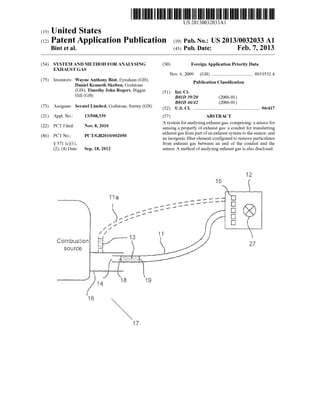
[0066] FIG. 1 depicts a system for analysing exhaust gas
emitted from a combustion source, eg a motor vehicle;
[0067] FIG. 2 depicts an example of a ?lter used in the
system of FIG. 1; and
[0068] FIG. 3 depicts an example of a housing for a ?lter
element; and
[0069] FIG. 4 depicts an on-board or in-line system for
analysing exhaust gas emitted from a combustion source.
[0070] Gas analysers can suffer from inaccurate analysis of
exhaust gases due to ?ne particulate matter, such as soot,
carried by the exhaust gases. The soot can block line ?lters
(e.g. ?lters made from paper, ?bre and plastic meshes e.g.
organic materials) and damage sensors measuring the gas
eous emissions. Paper ?lters also have relatively loW ?ltration
rates only ?ltering soot greater than 2 to 5 micron in siZe and
due to their loW surface area readily become blocked. The
problem of soot is particularly severe for emissions from
compression ignition engines, Where dedicated and expen
sive gas analysers are presently required.
[0071] To solve such a problem, the inventors attempted to
place a ?lter betWeen the gas analyser and the source of the
exhaust gases. The inventors tried using paper ?lters to ?lter
the soot from exhaust gas exiting a tailpipe upstream of sen
sors ofa standard (spark ignition) gas analyser. HoWever, the
inventors foundthat paper ?lters suffervarious problems such
as thermal damage due to the hot exhaust gas. Burning ofthe
paper ?lters created artifact emissions Which led to incorrect
readings by the gas analysers. Furthermore, the paper ?llers
absorbed llCs Which leads to incorrect 11C readings.
[0072] FIG. 1 depicts a system 10 for analysing exhaust gas
from combustion source, e.g. a motor vehicle. The system 10
comprises a conduit 11. The conduit 11 receives and/or trans
fers exhaust gas at least part Way from a tailpipe 16 ofa motor
vehicle to a gas analyser 12. The end of the tailpipe 16 is the
end of the exhaust system of a motor vehicle, Where the
exhaust gases expelled from the motorvehicle. The gas analy
ser 12 analyses a property ofthe exhaust gas using at least one
sensor 15, as described beloW. A ?lter element 13 is provided
upstream ofthe gas analyser 12 to ?lter the exhaust gas. The
?ltered exhaust gas is conveyed to the gas analyser via the
conduit 11. The conduit 11 can be dimensioned so that it can
be at least partially inserted into in the tailpipe. A part ofor the
Feb. 7, 2013
entire conduit 11 canbe inserted into the tailpipe. Exhaust gas
can enter the conduit 11. Exhaust gas can enter an opening 14
in the conduit 11.
[0073] Alternatively, the conduit 11 can be dimensioned to
?t around the tailpipe 16. This alloWs all ofthe exhaust gas to
be collected by the conduit 11. The conduit 11 can form an
air-tight seal around the tailpipe 16 so that only the exhaust
gas is conveyedto the gas analyser 12. The conduit 11 can also
be placed close to, but not into, the end ofthe tailpipe suchthat
exhaust gas is receivable by the conduit.
[0074] Alternatively, the conduit transfers exhaust gas at
least part Way from any part of an exhaust system through
Which exhaust gases ?oW (for example, a cylinder head, a
turbocharger, a catalytic converter, a pipe, a silencer, etc. . . .
). This is depicted in FIG. 1 by the dotted lines, Where the
conduit 11a is connectedto the tailpipe 16, up stream fromthe
end of the tailpipe 16 such that exhaust gas can enter the
conduit 11a. The ?ltered exhaust gas can be transferred to a
sensor that may be part of a management and/or monitoring
system that is part of a device incorporating a combustion
source, for example, may be part of a motor vehicle.
[0075] The exhaust gas received by the conduit 11 can be
conveyed to the ?lter element 13. The ?lter element 13 can be
placed anyWhere upstream of the conduit 11, along the con
duit 11 or in the gas analyser 12. Ifin the conduit 11, the ?lter
element 13 may be placed anyWhere from the opening 14 end
of the conduit 11 to the end adjacent to the gas analyser 12.
Alternatively, the ?lter element 13 can be attached to either
end ofthe conduit 11, but not Withinthe conduit, for example,
the ?lter element 13 can be attached to the opening 14 ofthe
conduit 11, such that the conduit 11 receives ?ltered exhaust
gas from the ?lter element 13. The ?lter element 13 can be
placed doWnstream or upstream of the opening 14 of the
conduit 11. The conduit 11 may be ?exible or solid. The
conduit 11 may be at least partially or even fully formed by
the ?lter element 13, housing 25 or even outer Walls of the
?lter element 13.
[0076] The ?lter element 13 and the sensor 15 may be
adjacent to each other. The ?lter element 13 and the adjacent
sensor 15 may be at least partially insertable into the end of
the tailpipe 16. The ?lter element 13 and the sensor 15 may be
housed in a probe that is insertable into the end ofthe tailpipe
16. The probe can form part of the conduit 11.
[0077] The conduit 11 and the ?lter element 13 can be
removably detachable from the tailpipe 16. The conduit 11
and the ?lter element 13 can also be removably detachable
fromthe gas analyser 12. The conduit 11 andthe ?lter element
13 can be separate and independent ofthe tailpipe and/or any
part ofthe motor vehicle. The system 10 can be separate and
independent of the tailpipe and/or any part of the motor
vehicle. The system 10 can be removably attachable to the
tailpipe and/or any part of the motor vehicle. The system 10
can be a stand alone unit for testing the emissions of a plu
rality ofvehicles.
[0078] Alternatively, the conduit (or sample line) can be
attached to any part of the exhaust system of a combustion
source to transfer exhaust gas to a sensor (or gas analyser).
The conduit (sample line) can be attached or placed upstream
from the end of an exhaust system or can be placed doWn
stream from the end ofthe exhaust system, but close enough
such that exhaust can be received by the conduit (sample
line). For example, the conduit (sample line) can be placed
upstream or doWnstream ofa diesel particulate ?lter. In other
examples, the conduit (sample line) can be placed or attached
9. US 2013/0032033 A1
upstream or downstream of a catalytic converter or on the
catalytic converter. In another example, the conduit (sample
line) can be placed or attached upstream or downstream of a
silencer or on the silencer of an exhaust system.
[0079] The sensor may be part ofa device that incorporates
a combustion source, for example, a sensor for a monitoring
and/or management system of a motor vehicle. The ?lter
element ?lters exhaust gas upstream of the sensor. The ?lter
element can ?lter exhaust gas doWnstream of the exhaust
system. The ?lter element can form part of the conduit for
transferring exhaust gas from any part of the exhaust system
to the sensor. The ?lter element may be removably attachable
from the motor vehicle.
[0080] Preferably, the ?lter element 13 has high ?ltration
ef?ciency (e.g. >80% in terms ofparticle mass and/or particle
number), high maximum operating temperature, loW thermal
expansion, resistance to thermal stress, high soot holding
capacity, thermal shock resistance, strength and mechanical
integrity and chemical resistance to metal oxides (ash)
present in particulates. The ?lter element should also be
chemically stable, being resistant to exhaust gas components
(including sulphur), have a loW reactivity With ash com
pounds and oxidation resistance. The ?lter element 13 can be
made from a number ofmaterials, as discusses beloW, to meet
these criteria.
[0081] Furthermore, the ?lter element 13 should have a loW
pressure drop across it When empty or loaded With particu
lates and ashes. Also the ?lter element 13 should have a loW
scatter ofpressure drop (i.e., repeatable pressure drop values
at a given gas ?oW rate and soot load).
[0082] The ?lter element 13 can be made from an inorganic
material, such as carbides, silicates, oxides, titantates, SiC,
cordierite, ceramics, metals, alloys or minerals or the like.
The term inorganic is used to exclude, for example, petro
chemical or pertochemically derived materials and materials
derived from living organisms. In one embodiment, the ?lter
element 13 can be made from any suitable material that is
inert to exhaust gas.
[0083] A ?lter element made from an inorganic material
can provide a thermally and chemically stable ?lter element
for removing particulates from exhaust gas. An inorganic
?lter element does not suffer from problems such as burning
at high temperatures. Thus the gas analyser 12 readings are
more accurate as artefacts due to burning are not introduced
into the exhaust gas upstream from the sensor 15. Further
more, due to the increased thermal stability, the exhaust gas
does not need to be cooled prior to ?ltering. Thus the system
10 is simpler, cheaper and more lightWeight than ?llers Which
require cooling of the exhaust gas. Also, the manufacturing
process for the system 10 is more e?icient.
[0084] The ?lter element 13 can be made from a silicate or
carbide. The ?lter element 13 can be made from a non-me
tallic carbide (such as SiC) or a metal silicate (such as cordi
erite). These classes ofmaterials are Well suited to this appli
cation, as described beloW.
[0085] Ceramics, such as SiC and cordierite (Which is a
magnesium iron aluminium cyclosilicate), and metals, such
as stainless steel and Fe Cr alloy, such as Fecralloy (RTM)
available from GoodfelloW Cambridge Ltd, Huntingdon. UK,
can be made to be porous to the exhaust gas. Sintering, or any
other suitable manufacturing method, can be used to form
porous ceramics, metals or any other suitable material (for
example, plastics). The ?lter element 13 can be made from
sintered materials. The porosity of a material can be easily
Feb. 7, 2013
controlled during the sintering process. Thus a ?lter element
13 can be formed With a required porosity that is uniform
throughout the ?lter element 13. Sintering alloWs relatively
small pores to be formed. The pore siZe can also be easily
controlled during the sintering process. The ?lter element 13
is therefore less likely to have large defective pores that alloW
particulates to pass through the ?ler 13. Complicated shapes
can also be easily formed using the sintering process. Addi
tionally, a sintered material is likely to be inert to exhaust gas
because it has already been raised to a temperature far above
the temperature ofthe exhaust gas. The ?lter element 13 can
be made from ceramic and/or metal ?bres or meshes.
[0086] The exhaust gases emitted from the tailpipe 16 of a
motor vehicle 17 can be corrosive and hot. The exhaust gases
can have temperatures of around 300° C. The exhaust gases
can reach temperatures ofup to 750° C. Thus, preferably, the
?lter element 13 is made from a material that is inert to
exhaust gases at temperatures above about 250° C. (around
300° C.) and preferably up to 750° C. The material does not
need to be inert to exhaust gases at a temperature of over
1000° C. for example.
[0087] Burning caused by the heat from the exhaust gas can
cause gases and/or particulates to be introduced into to the
exhaust gas stream. The inventors have tried ?lters made from
paper, Which has an auto-ignition temperature ofaround 450°
C. HoWever, it Was found by the inventors that the paper
burned in the hot exhaust gas. It is therefore desirable that the
?lter element 13 is made from a material that has an auto
ignitiontemperature above the temperature ofthe exhaust gas
and preferably above 500° C.
[0088] The above physical requirements can be met by, for
example, silicon carbide, for example, silicon carbide coated
alumina ?bres, cordierite, aluminium titanate, sintered met
als, metal meshes and knitted Wires, ceramic ?bres, ceramic
marts and meshes, silica ?bres, asbestos and ceramic foams.
[0089] A clogged ?lter can be regenerated by healing the
?lter element 13 to above 600° C. Above this temperature, the
particulates (Which are mainly made up of carbon) start to
oxidise into gases (such as C02). The ?lter element 13 can
reach temperatures above 750° C. during regeneration.
Therefore it is desirable that the ?lter element 13 is made from
a material, such as SiC or cordierite, that is thermally and
chemically stable at these temperatures. The ?lter element 13
can be reused after regeneration. A ?lter made from SiC or
cordierite, for example, can be regenerated around 10 times.
[0090] Filters made from materials With a relatively high
thermal conductivity, such as SiC, can also be desirable.
During combustion ofthe particulates, a large amount ofheat
is produced. This heat needs to be dissipated throughout the
?lter body. If the thermal conductivity is too loW, local hot
spots arise, Which may lead to decomposition of the ?lter
material, especially in materials Where the melting point is
relatively loW. The high thermal conductivity of SiC helps
prevent the occurrence of hot spots and thus provides ?lters
that have increased stability.
[0091] Impacts during use damage the ?lter element 13.
Thus it is preferable that the ?lter element 13 has high struc
tural strength. Dueto repeatedheating andcooling ofthe ?lter
(When in use and When it is regenerated), it is also preferable
that the ?lter has high thermal and mechanical durability.
[0092] In certain circumstances, it may be desirable that the
tiller element 13 is made from a material that is porous to
exhaust gas. A ?lter element 13 made from a material that is
porous to exhaust gas can provide a structurally and thermally
10. US 2013/0032033 A1
stable material for removing particulates from exhaust gas. A
porous material can maintain its shape When heal and/or
pressure is applied to it. Furthermore, the pore siZe canremain
constant under heat and/or pressure.
[0093] In certain circumstances, metallic ?bre or mesh ?l
ters made from materials that are not porous to exhaust gas
can easily deform When heat and/or pressure is applied to it.
This deformation can lead to a change in siZe of the gaps
betWeen the ?bres. This change can lead to an undesired
change in the siZe of particulates ?ltered and a change in the
How rate through the metallic ?bre or mesh ?lter.
[0094] Furthermore, in certain circumstances, a ?lter made
of a porous material may have a better thermal conductivity
than metallic a ?bre or mesh ?lter made from a non-porous
material. Fibres at a front face ofa ?lter, that is exposed to hot
exhaust gas, may become very hot as the ?bres may have
limited conduction paths, thus restricting the ability to dissi
pate heat through the ?lter. In certain circumstances, due to
the lack ofheal dissipation, the ?bres may become hot enough
to burn. As described above, burning could introduce artefacts
into the exhaust gas Which could lead to inaccurate readings
by the sensor 15. A ?lter made from a porous material can
have better thermal properties because more ofthe solid com
ponents of the material are in contact With each other, thus
alloWing the heat to conduct aWay. Furthermore, in certain
circumstances, Wire meshes may not be able to ?lter small
panicles less than 2 microns in siZe. Also, in certain circum
stances, Wire meshes may act as a catalyst to the exhaust gases
so that the exhaust gases react and change character before
reaching the sensor, thus providing inaccurate readings.
[0095] The ?lter element 13 can be a single structure, or
element. The ?lter element does not require another compo
nent or part to function as a ?lter.
[0096] The exhaust gas emissions from a motor vehicle can
comprise particulates ranging in siZe from 20 nm to over 10
um. Particulates greater than 100 nm in siZe can damage
sensors and can cause false readings. The ?lter element 13 can
remove (eg all) particulates greater than about 100 nm pref
erably 500 nm and more preferably 100 nm in siZe from the
exhaust gas. Therefore, the ?lter element ?lters particles
doWn to (and optionally not including) 1000 nm (preferably
500 nm. more preferably 100 nm) from the exhaust gas. By
?ltering doWn to these siZes it is possible to achieve good How
rates With a smaller ?ltration area. Removing particles above
the above mentioned siZes from the exhaust gas prevents
damage to the sensors.
[0097] Filtering small particles requires a ?lter element 13
With small pore siZes. This can lead to a loW ?oW rate of
exhaust gas through the ?lter element 13. Furthermore, a ?lter
element 13 With a small pore siZe can quickly become
clogged. Thus it may be preferable to provide a ?lter element
13 that has large pore siZes and thus ?lters larger particulates,
for example particulates greater than about 100 nm in siZe.
This can lead to in increase in the How rate. It is therefore
preferable that the ?lter is made from a material With pore
siZes betWeen 5 um and 60 um, preferably 10 pm to 40 um,
and preferably betWeen 10 um and 20 um.
[0098] More than one ?lter element 13 may be utilised. For
example, the system may comprise tWo ?lters (in series and/
or in parallel depending on the arrangement). Each ?lter may
be arranged to ?lter a different range of particle siZes. For
example, a ?lter that ?lters large particles can be placed
upstream from a ?lterthat ?lters smallerparticles. Filters With
small pore siZes can quickly become blocked With large par
Feb. 7, 2013
ticles. Thus providing a ?lter With large pore siZes to ?lter the
large particles from the exhaust gas upstream from a ?lter
With small pore siZes can help provide a system Which can
?lter a lager range of particle siZes for a larger volume of
exhaust gas compared to a single ?lter With small pore siZes.
A good How rate can also be maintained over a larger volume
of?ltered exhaust gas as there may be a smaller total pressure
drop over the tWo ?lters compared to a single clogged ?lter
With small pores.
[0099] The exhaust gas can enter the ?lter element 13 at an
inlet end face 18. The inlet end face 18 is the face ofthe ?lter
element 13 that is exposed to the How ofthe exhaust gas. The
exhaust gas passes through the ?lter element 13 and exits the
?lter element 13 at an outlet end face 19. The ?ltered exhaust
gas is then conveyed (via, for example, the conduit 11) to the
gas analyser 12.
[0100] The gas analyser 12 comprises at least one sensor 15
to measure at least one property of the ?ltered exhaust gas.
Preferably, the sensors 15 ofthe gas analyser 12 measure the
quantity ofgases, such as CO, HC, NOX, CO2, 02, SOX, inthe
exhaust gas. The sensors 15 can be arranged to measure the
absolute quantity and/or the relative quantity of the gases in
the exhaust gas. The gas analyser 12 can measure one or more
ofthe gases, and preferably four or more of the gases.
[0101] The concentration of the gases measured can be
used, for example, to determine a condition of the motor
vehicle 17 or determine if the emissions meet certain stan
dards. The gas measurements by the gas analyser 12 can
provide information that can be used to diagnose a number of
problems ofthe motor vehicle 17. Such problems can include
drive ability issues, ignition system problems, fuel manage
ment issues, engine mechanical problems, excessive emis
sions problems and many others. The gas analyser 12 may be
separate and independent ofthe motor vehicle 17 and not part
ofany internal systems ofthe motor vehicle 17. Alternatively,
the gas analyser 12 may be carried on board as part of a
monitoring system for on board diagnostics.
[0102] Gas analysers, such as the four/?ve gas analysers
that are commonly used to measure the emissions from spark
ignition engines can be used as part of the system 10. These
four/?ve gas analysers are normally unsuitable for measuring
emissions from compression ignition engines clue to the
amount of soot produced. HoWever, the ?lter element 13 can
remove the soot to alloW the four/?ve gas analysers to be
measure emissions from compression ignition engines.
[0103] The gas analyser 12 can comprise a vacuum pump
27 Whichprovides suction for forcing the exhaust gas through
the ?lter element 13 and toWards the gas analyser 12. Alter
natively or additionally, a vacuum pump 27 can be provided
that is separate from the gas analyser 12. The vacuum pump
27 can be con?gured to provide a constant ?oW-rate of
exhaust gas to the gas analyser 12. The ?lter element 13 can
become blocked as the collected particulates build-up Within
the ?lter element 13. This leads to a decrease in the ?oW-rate
of exhaust gas through the ?lter element 13. The vacuum
pump 27 can be con?gured to adjust the partial vacuum to
compensate forthe increasedblockage in the ?lter element 13
to maintain a constant ?oW-rate.
[0104] Preferably, the ?lter element 13 has a relatively loW
pressure drop across it and a relatively high ?ltration e?i
ciency. A loW pressure drop is desirable to maximise the HoW
rate ofthe exhaust gas through the ?lter. A loW pressure drop
also reduces the backpressure, thus more exhaust gas is able
11. US 2013/0032033 A1
to be draWn into the ?lter. Furthermore, the loW pressure drop
requires the vacuum pump to do less Work to suck exhaust gas
through the ?lter.
[0105] To obtain a high ?oW rate, it is preferable that the
?lter has a porosity of betWeen about 30 and 50%. This
provides a reduction in the backpressure and alloWs the
exhaust gas to arrive at the sensor With minimal delay. This is
especially advantageous When the exhaust gas is being mea
sured as a function of time.
[0106] The ?lter element 13 can be formed from a porous
ceramic or metallic block. The effective ?ltration area can be
de?ned as the total area ofthe ?lter medium that is exposed to
How and is usable for the ?ltration process. The effective
?ltration area for a block With a ?at face at the inlet end face
18 is the area of the face. It may be desirable to increase the
effective ?ltration area to increase the ?ltration ef?ciency.
[0107] The effective ?ltration area of the ?lter element 13
can be increased by increasing the siZe of inlet end face 18.
HoWever, this may not be practical, especially if the ?lter
element 13 is part ofa probe 15 that is inserted into the tailpipe
16.
[0108] The ?lter element 13 may be shaped into a cuboid, a
polyhedron, a cylinder or the like. The ?lter element 13 may
have a cross-sectional area ofbetWeen 0.1 and 0.6 cm2 and a
length ofbetWeen 1 cm and 4 cm. For example, a cylindrical
?lter element 13 can have, a diameter ofbetWeen 1 and 3 cm
and desirably around 1.5 cm, and a length of betWeen 1 cm
and 3 cm and preferably around 2.5 cm.
[0109] The effective ?ltration area of the ?lter element 13
can be betWeen 0.1 m2 and 0.6 m2. The ?lter element can have
a ?ltration area ofaround 0.4 to 0.6 m2 per litre ofvolume. A
Wall-?ow ?lter can provide a large effective ?ltration area,
While having a small volume. The Wall-?ow ?lter can be
shaped to be a polyhedron, a cylinder or the like. The ?lter
element 13 can be a Wall-?ow ?lter.
[0110] FIG. 2 depicts part ofa cross-section ofa Wall-?ow
?lter 20. The Wall-?ow ?lter 20 comprises a plurality of
interconnected porous Walls 21. The Walls 21 de?ne a plural
ity of exhaust gas inlet channels 22 (also referred to as “inlet
cells”) and a plurality ofexhaust gas outlet channels 23 (also
referred to as “outlet cells”). The inlet and outlet cells 22 and
23 extend longitudinally from the inlet end face 18 to the
outlet end face 19 ofthe ?lter 20. The Walls 21 ofthe inlet cells
22 provide a large surface area, Which is exposed to the How
of the exhaust gas, thus providing a large effective ?ltration
area. The cells 22 and 23 can have a cross-section of any
shape, particularly those that can be close packed but includ
ing, for example, squares, hexagons, octagons, rectangles,
circles, triangles and combinations thereof. The Wall-?ow
?lter 20 can have a honeycomb structure.
[0111] The inlet cells 22 are open at the inlet face end 18
and closed at the outlet face end 19. The outlet cells 23 are
adjacent to the inlet cells 22. The outlet cells 23 are open at the
outlet face end 19 and closed at the inlet face end 18. The inlet
and outlet cells 22 and 23 can be closed at one end by using a
suitable plugging material orby any othermeans that does not
alloW the exhaust gas to pass through it.
[0112] The exhaust gas enters the inlet cells 22 at the inlet
end face 18. The inlet cell is closed at the opposite end to
prevent the exhaust gas from passing straight through the
Wall-?ow ?lter 20. Thus the exhaust gas is forced through the
porous Walls 21, Which retains the particulates from the
exhaust gas. The particulates can become trapped on the
surface of the Walls 21 of the inlet cell or in the pores of the
Feb. 7, 2013
Wall. The ?ltered exhaust gas enters an adjacent outlet cell
and exits the Wall-?ow ?lter 20 from the outlet end face 19.
The How arroWs in FIG. 2 illustrate the How path that exhaust
gas takes through the inlet and outlet cells 22 and 23.
[0113] The porosity ofWall material is preferably betWeen
about 30% to 50%, by volume. To achieve loW backpressure,
the porosity of the Walls 21 may be made to be greater than
60%. To maintain structural strength ofthe Wall-?ow ?lter 20,
the total porosity ofthe Walls 21 should desirably be less than
about 40%.
[0114] The Wall thickness may be betWeen 0.2 and 1 mm. In
certain circumstances, to ensure adequate structural strength
and ?ltration ef?ciency of the Wall-?ow ?lter 20, the Wall
thickness may be greater than about 0.4 mm (With a porosity
value of about 40%). To ensure relatively loW backpressure,
the Wall thickness may be less than 0.8 mm. To ensure high
?ltration ef?ciency With relatively loW backpressure the Wall
thickness (W) and pore siZe (PS) may be selected such that the
W/PS ratio is greater than 0.4. Preferably, the Wall thickness
is betWeen about 0.3 and 0.5 mm.
[0115] A Wall-?ow ?lter 20 With a cell siZe that is too small
can become easily clogged. Conversely, a Wall-?ow ?lter 20
With a cell siZe that is too big can have a loW ?ltration e?i
ciency. A cell With a cross-sectional area of betWeen 0.1 and
0.6 cm2 can provide a good balance betWeen the ?ltration
ef?ciency and the rate of blockage.
[0116] Furthermore, a good balance can also be achieved
With a cell density of betWeen around 588 to 1290 cells per
square centimeter (90 to 200 cells per square inch.
[0117] As shoWn in FIG. 3, any ofthe above described ?lter
elements 13 can be provided With a housing 24 that alloWs the
?lter element 13 to be easily removed and re-inserted into the
system 10. The housing 24 can, for example, be connectable
to the conduit 11. The housing 25 may also comprise a heater
25 to heat the ?lter element 13. A metallic ?lter could be
heated by providing a current. In some circumstances, HCs
from the exhaust gas can absorb onto certain materials. By
heating the ?lter element 13 to around 3000 C. the HCs it may
be possible to stop absorption of the HCs on to the ?lter 12.
The heater 24 can also heat the ?lter element 13 to around
6000 C. to regenerate the ?lter element 13 (eg to remove the
solid soot particulates).
[0118] FIG. 4 illustrates a further embodiment Which is the
same as the foregoing embodiments except as described
beloW. Features from any embodiment may be present in any
other embodiment. For example, in the embodiment of FIG.
4, a diesel particulate ?lter 30 is illustrated in the tail pipe 16.
The diesel particulate ?lter 30 is upstream ofthe ?lter element
13. Such a diesel particulate ?lter 30 may be present in any
other embodiment.
[0119] In the embodiment of FIG. 4, the gas analyZer 12 is
mounted on the vehicle 17 and is normally part ofthe vehicle
17. That is, the gas analyZer 12 is on board the vehicle 17
during normal use. This alloWs in-line analyZing of exhaust
gas emissions. To this end, the ?lter element 13 is perma
nently mounted inthe tail pipe 16 (it may be removable so that
it can be replaced and/or cleaned). The conduit for transfer
ring exhaust gas from part ofthe exhaust system to the sensor
is partly made up ofthe housing ofthe ?lter element 13 so that
the ?lter element 13 is con?gured to remove particles from
exhaust gas betWeen an end ofthe conduit and the sensor 15.
Alternatively the ?lter element 13 may be in a branch line off
the tail pipe 16, such as is illustrated in FIG. 1.
12. US 2013/0032033 A1
[0120] The ?lter element 13 is downstream of the diesel
particulate ?lter 30. However, this is not necessarily the case
and the ?lter element 13 could be positioned upstream ofthe
diesel particulate ?lter 30.
[0121] The sensor 15 is not for measuring the ?ltering
performance of the ?lter element 13 or for measuring the
character or presence of soot. The sensor 15 is for analyZing
gaseous components ofthe exhaust gas. The sensor 15 is for
sensing a properly (e.g. concentration ofgases) ofthe exhaust
gas. The sensor 15 is not for measuring the pressure of the
exhaust gas. The sensor 15 is for measuring the composition
ofexhaust gas, for example the composition ofa sample taken
from the exhaust gas.
[0122] The sensor 15 is ofthe type deleteriously effected by
panicles in the gas being sampled.
[0123] The present invention can be utilised in areas other
than motor vehicles. The invention can be applied to emis
sions from, for example, furnaces, boilers, heat generators,
electricity generators, poWer plants or any other emissions
resulting from the combustion of fuel.
1. A system for analysing exhaust gas, comprising:
a sensor for sensing a property of exhaust gas;
a conduit for transferring exhaust gas from part of an
exhaust system to the sensor; and
an inorganic ?lter element con?gured to remove particu
lates from exhaust gas betWeen an end ofthe conduit and
the sensor.
2. A system for analysing exhaust gas, comprising:
a sensor for sensing a property of exhaust gas;
a conduit for transferring exhaust gas from part of an
exhaust system to the sensor; and
a porous ?lter element, Wherein the ?lter element is inert to
exhaust gas and is con?gured to remove particulates
from exhaust gas betWeen an end ofthe conduit and the
sensor.
3. A system according to any one ofthe preceding claims,
Wherein the material of the ?lter element is sintered.
4. A system according to any one ofthe preceding claims,
Wherein the ?lter element is inert to exhaust gas at tempera
tures greater than 300° C., preferably up to 750° C.
5. A system according to any one ofthe preceding claims,
Wherein the ?lter element is arranged to remove particulates
With a siZe doWn to but not including about 1000 nm from
exhaust gas.
6. A system according to claim 5, Whereinthe ?lter element
is arranged to remove particulates With a siZe doWn to but not
including about 500 nm, desirably 100 nm from exhaust gas.
7. A system according to any one ofthe preceding claims,
Wherein the ?lter element is made from a material selected
from a group consisting of ceramics, metals, glasses and
minerals.
8. A system according to any one ofthe preceding claims,
Wherein the ?lter element is made from a material selected
from a group consisting of silicates carbides, oxides and
titanates.
9. A system according to claim 8, Whereinthe ?lter element
is made from a material selected from a group consisting of
metal silicates, non-metallic carbides, metallic titanates and
non-metallic oxides.
10. A system according to any one ofthe preceding claims,
Wherein the ?lter is made from a material selected from a
group consisting of silicon carbide, cordierite, aluminium
titanate, silica and asbestos.
Feb. 7, 2013
11. A system according to any one ofthe preceding claims,
Wherein the ?lter element is made from a material porous to
exhaust gas.
12. A system according to any one ofthe preceding claims,
Wherein the ?lter element is made from ?bres or a mesh or a
foam.
13. A system according to any one ofthe preceding claims,
Wherein the ?lter element has an auto-ignition temperature of
greater than 5000 C.
14. A system according to any one ofthe preceding claims,
Wherein the conduit and/or ?lter element are at least partially
insertable into or attachable to the end of a tailpipe.
15. A system according to any one of the above claims,
Wherein the ?lter element has a ?ltration area greater than
around 0.05 m2.
16. A system according to any one of the above claims,
Wherein the ?lter element has an effective ?ltration area less
than around 0.6 m2.
17. A system according to any one ofthe preceding claims
Wherein ?lter element has ?ltration ef?ciency greater than
around 80%.
18. A system according to any one ofthe preceding claims,
Wherein the ?lter element comprises a plurality of porous
Walls.
19. A system according to claim 18, Wherein the Walls have
a pore siZes smaller than 50 um, preferably smaller than 20
um.
20.A system according to claim 18 or 19, Wherein the Walls
have a porosity of around 30 to 60%.
21. A system according to any one of claims 18 to 20,
Wherein the thickness of the Walls is around 0.2 to 1 mm,
preferably 0.3 to 0.5 mm.
22. A system according to any one ofthe preceding claims,
Wherein the ?lter element is a Wall-?ow ?lter.
23. A system according to any one of claims 18 to 22,
Wherein the plurality ofporous Walls de?ne a plurality ofinlet
cells and a plurality of outlet cells that extend from an inlet
end face ofthe ?lter element to the outlet end face ofthe ?lter
element.
24. A system according to claim 23, Wherein the inlet cells
are open at the inlet end face and closed at or near the outlet
end face and the outlet cells are open at the outlet end face and
closed at or near the inlet end face.
25. A system according to claim 24, Wherein the inlet cells
are arranged to alloW exhaust gas to enter the ?lter element at
the inlet end face and substantially stop at least particulates
from exiting the inlet cell at the outlet end face and Wherein
the outlet cells are arranged to alloW the exhaust gas to exit the
?lter element at the outlet end face and stop exhaust gas from
exiting the ?lter element at the inlet end face.
26. A system according to any one of claims 23 to 25,
Wherein the ?lter element has a cell density of around 550 to
1300 cells per square centimetre (90 to 200 cells per square
inch).
27. A system according to any one ofthe preceding claims,
Wherein the ?lter element has a honeycomb structure.
28. A system according to any one ofthe preceding claims,
Wherein the conduit transfers exhaust gas from the end of an
exhaust system.
29. A system according to claim 28, Wherein the end of an
exhaust system is the end of a tailpipe.
30. A system according to any one ofthe preceding claims,
Wherein the exhaust system is part of a motor vehicle.
13. US 2013/0032033 A1
31. A system according to any one ofthe preceding claims,
further comprising a ?lter housing to house the ?lter element.
32. A system according to any one ofthe preceding claims,
further comprising a heating device to heat the ?lter element.
33. A system according to claim 30, Wherein the heating
device is comprised Within the ?lter housing.
34. A system according to claim 30 or 31, Wherein the
heating device is arranged to heat the ?lter element to above
250° C., preferably above 600° C.
35. A system according to any one ofthe preceding claims,
further comprising a vacuum pump arranged to suck exhaust
gas through the ?lter element.
36. A system according to any one ofthe preceding claims,
Wherein the sensor is arranged to measure the concentration
of one or more ofthe gases selected from a group consisting
ofhydrocarbons, carbon monoxide, nitrogen oxides, carbon
dioxide and oxygen.
37. A method of analysing exhaust gas using a system
according to any one ofthe preceding claims, comprising the
steps of:
using the conduit to transfer exhaust gas part of an exhaust
system to the sensor;
forcing the exhaust gas through the ?lter element Which is
positioned betWeen an end ofthe conduit and the sensor;
and
sensing a property of the ?ltered exhaust gas using the
sensor.
Feb. 7, 2013
38. A method of analysing exhaust gas comprising the
steps of:
transferring exhaust gas from part of an exhaust system to
a sensor via a conduit;
?ltering the exhaust gas to remove particulates by forcing
the exhaust gas through an inorganic ?lter element,
Wherein the ?lter element is positioned betWeen an end
of the conduit and the sensor; and
sensing a property of the ?ltered exhaust gas.
39. A method according to claim 38, Wherein the ?lter
element is made from a material porous to exhaust gas.
40. A method according to any one of claims 37 to 39,
further comprising the step of:
inserting or attaching the conduit and/or ?lter element to
the end of a tailpipe.
41. A ?lter element for ?ltering exhaust gas in a system for
analysing exhaust gas, the ?lter element being made of an
inorganic material and being con?gured to remove particu
lates from exhaust gas, Wherein the ?lter element is betWeen
an end ofa conduit fortransferring exhaust gas from part ofan
exhaust system and a sensor for sensing a property ofexhaust
gas.
42. A system constructed and arranged to operate substan
tially as hereinbefore described With reference to the accom
panying draWings.
43. A method substantially as hereinbefore described With
reference to the accompanying draWings.
* * * * *