Introduction: Datacommunication: Components, Data
representation, Data flow, Networks: Network criteria, Physical
Structures, Network types: LAN, WAN, Switching, The
Internet.. Network Models: TCP/IP Protocol Suite: Layered
Architecture, Layers in TCP/IP suite, Description of layers,
Encapsulation and Decapsulation, Addressing, Multiplexing and
Demultiplexing, The OSI Model: OSI Versus TCP/IP.
Data-Link Layer: Introduction: Nodes and Links, Services, Two
Categories’ of link, Sublayers, Link Layer addressing: Types of
addresses, ARP
MODULE -1
3.
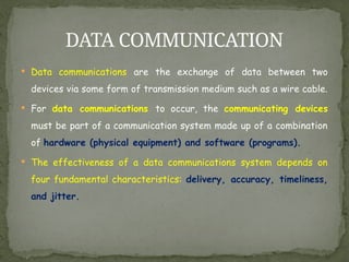
Data communicationsare the exchange of data between two
devices via some form of transmission medium such as a wire cable.
For data communications to occur, the communicating devices
must be part of a communication system made up of a combination
of hardware (physical equipment) and software (programs).
The effectiveness of a data communications system depends on
four fundamental characteristics: delivery, accuracy, timeliness,
and jitter.
DATA COMMUNICATION
4.
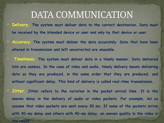
Delivery. Thesystem must deliver data to the correct destination. Data must
be received by the intended device or user and only by that device or user.
Accuracy. The system must deliver the data accurately. Data that have been
altered in transmission and left uncorrected are unusable.
Timeliness. The system must deliver data in a timely manner. Data delivered
late are useless. In the case of video and audio, timely delivery means delivering
data as they are produced, in the same order that they are produced, and
without significant delay. This kind of delivery is called real-time transmission.
Jitter. Jitter refers to the variation in the packet arrival time. It is the
uneven delay in the delivery of audio or video packets. For example, let us
assume that video packets are sent every 30 ms. If some of the packets arrive
with 30-ms delay and others with 40-ms delay, an uneven quality in the video is
the result.
DATA COMMUNICATION
5.
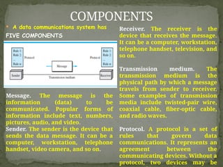
A datacommunications system has
FIVE COMPONENTS
COMPONENTS
Message. The message is the
information (data) to be
communicated. Popular forms of
information include text, numbers,
pictures, audio, and video.
Sender. The sender is the device that
sends the data message. It can be a
computer, workstation, telephone
handset, video camera, and so on.
Receiver. The receiver is the
device that receives the message.
It can be a computer, workstation,
telephone handset, television, and
so on.
Transmission medium. The
transmission medium is the
physical path by which a message
travels from sender to receiver.
Some examples of transmission
media include twisted-pair wire,
coaxial cable, fiber-optic cable,
and radio waves.
Protocol. A protocol is a set of
rules that govern data
communications. It represents an
agreement between the
communicating devices. Without a
protocol, two devices may be
6.
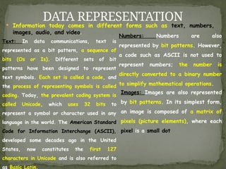
Information todaycomes in different forms such as text, numbers,
images, audio, and video.
DATA REPRESENTATION
Text: In data communications, text is
represented as a bit pattern, a sequence of
bits (Os or Is). Different sets of bit
patterns have been designed to represent
text symbols. Each set is called a code, and
the process of representing symbols is called
coding. Today, the prevalent coding system is
called Unicode, which uses 32 bits to
represent a symbol or character used in any
language in the world. The American Standard
Code for Information Interchange (ASCII),
developed some decades ago in the United
States, now constitutes the first 127
characters in Unicode and is also referred to
as Basic Latin.
Numbers: Numbers are also
represented by bit patterns. However,
a code such as ASCII is not used to
represent numbers; the number is
directly converted to a binary number
to simplify mathematical operations.
Images: Images are also represented
by bit patterns. In its simplest form,
an image is composed of a matrix of
pixels (picture elements), where each
pixel is a small dot
7.
DATA REPRESENTATION
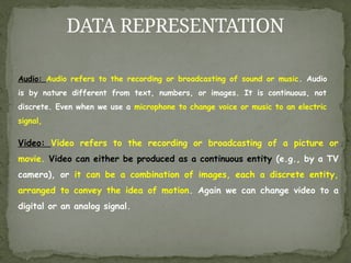
Video: Videorefers to the recording or broadcasting of a picture or
movie. Video can either be produced as a continuous entity (e.g., by a TV
camera), or it can be a combination of images, each a discrete entity,
arranged to convey the idea of motion. Again we can change video to a
digital or an analog signal.
Audio: Audio refers to the recording or broadcasting of sound or music. Audio
is by nature different from text, numbers, or images. It is continuous, not
discrete. Even when we use a microphone to change voice or music to an electric
signal,
8.
DATA FLOW
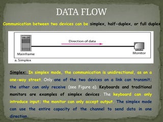
Communication betweentwo devices can be simplex, half-duplex, or full duplex
Simplex: In simplex mode, the communication is unidirectional, as on a
one-way street. Only one of the two devices on a link can transmit;
the other can only receive (see Figure a). Keyboards and traditional
monitors are examples of simplex devices. The keyboard can only
introduce input; the monitor can only accept output. The simplex mode
can use the entire capacity of the channel to send data in one
direction.
9.
DATA FLOW
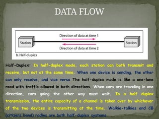
Half-Duplex: Inhalf-duplex mode, each station can both transmit and
receive, but not at the same time. When one device is sending, the other
can only receive, and vice versa The half-duplex mode is like a one-lane
road with traffic allowed in both directions. When cars are traveling in one
direction, cars going the other way must wait. In a half duplex
transmission, the entire capacity of a channel is taken over by whichever
of the two devices is transmitting at the time. Walkie-talkies and CB
(citizens band) radios are both half-duplex systems.
10.
DATA FLOW
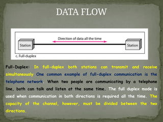
Full-Duplex: Infull-duplex both stations can transmit and receive
simultaneously One common example of full-duplex communication is the
telephone network. When two people are communicating by a telephone
line, both can talk and listen at the same time. The full duplex mode is
used when communication in both directions is required all the time. The
capacity of the channel, however, must be divided between the two
directions.
11.
NETWORKS: Network Criteria,Physical
Structures
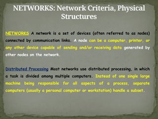
NETWORKS A network is a set of devices (often referred to as nodes)
connected by communication links. A node can be a computer, printer, or
any other device capable of sending and/or receiving data generated by
other nodes on the network.
Distributed Processing Most networks use distributed processing, in which
a task is divided among multiple computers. Instead of one single large
machine being responsible for all aspects of a process, separate
computers (usually a personal computer or workstation) handle a subset.
12.
NETWORKS: Network Criteria,Physical
Structures
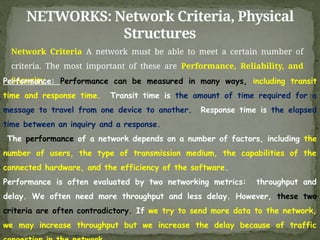
Network Criteria A network must be able to meet a certain number of
criteria. The most important of these are Performance, Reliability, and
Security.
Performance: Performance can be measured in many ways, including transit
time and response time. Transit time is the amount of time required for a
message to travel from one device to another. Response time is the elapsed
time between an inquiry and a response.
The performance of a network depends on a number of factors, including the
number of users, the type of transmission medium, the capabilities of the
connected hardware, and the efficiency of the software.
Performance is often evaluated by two networking metrics: throughput and
delay. We often need more throughput and less delay. However, these two
criteria are often contradictory. If we try to send more data to the network,
we may increase throughput but we increase the delay because of traffic
13.
NETWORKS: Network Criteria,Physical
Structures
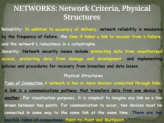
Reliability: In addition to accuracy of delivery, network reliability is measured
by the frequency of failure, the time it takes a link to recover from a failure,
and the network's robustness in a catastrophe.
Security: Network security issues include protecting data from unauthorized
access, protecting data from damage and development, and implementing
policies and procedures for recovery from breaches and data losses.
Physical Structures
Type of Connection A network is two or more devices connected through links.
A link is a communications pathway that transfers data from one device to
another. For visualization purposes, it is simplest to imagine any link as a line
drawn between two points. For communication to occur, two devices must be
connected in some way to the same link at the same time. There are two
possible types of connections: Point-to-Point and Multipoint.
14.
NETWORKS: Network Criteria,Physical
Structures
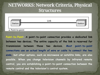
Point-to-Point: A point-to-point connection provides a dedicated link
between two devices. The entire capacity of the link is reserved for
transmission between those two devices. Most point-to-point
connections use an actual length of wire or cable to connect the two
ends, but other options, such as microwave or satellite links, are also
possible. When you change television channels by infrared remote
control, you are establishing a point-to-point connection between the
remote control and the television's control system.
15.
NETWORKS: Network Criteria,Physical
Structures
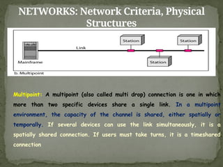
Multipoint: A multipoint (also called multi drop) connection is one in which
more than two specific devices share a single link. In a multipoint
environment, the capacity of the channel is shared, either spatially or
temporally. If several devices can use the link simultaneously, it is a
spatially shared connection. If users must take turns, it is a timeshared
connection
16.
NETWORKS: Network Criteria,Physical
Structures
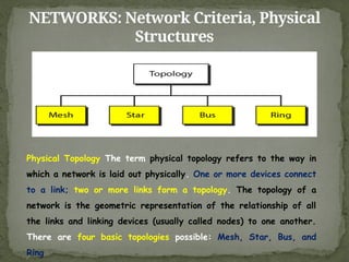
Physical Topology The term physical topology refers to the way in
which a network is laid out physically. One or more devices connect
to a link; two or more links form a topology. The topology of a
network is the geometric representation of the relationship of all
the links and linking devices (usually called nodes) to one another.
There are four basic topologies possible: Mesh, Star, Bus, and
Ring
17.
NETWORKS: Network Criteria,Physical
Structures
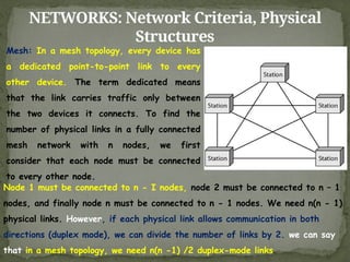
Mesh: In a mesh topology, every device has
a dedicated point-to-point link to every
other device. The term dedicated means
that the link carries traffic only between
the two devices it connects. To find the
number of physical links in a fully connected
mesh network with n nodes, we first
consider that each node must be connected
to every other node.
Node 1 must be connected to n - I nodes, node 2 must be connected to n – 1
nodes, and finally node n must be connected to n - 1 nodes. We need n(n - 1)
physical links. However, if each physical link allows communication in both
directions (duplex mode), we can divide the number of links by 2. we can say
that in a mesh topology, we need n(n -1) /2 duplex-mode links
18.
NETWORKS: Network Criteria,Physical
Structures
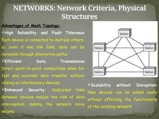
Advantages of Mesh Topology:
High Reliability and Fault Tolerance
Each device is connected to multiple others,
so even if one link fails, data can be
rerouted through alternative paths.
Efficient Data Transmission
Direct point-to-point connections allow for
fast and accurate data transfer without
relying on intermediary devices.
Enhanced Security: Dedicated links
between devices reduce the risk of data
interception, making the network more
secure.
Scalability without Disruption:
New devices can be added easily
without affecting the functionality
of the existing network.
19.
NETWORKS: Network Criteria,Physical
Structures
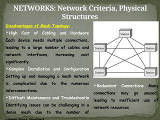
Disadvantages of Mesh Topology:
High Cost of Cabling and Hardware
Each device needs multiple connections,
leading to a large number of cables and
network interfaces, increasing cost
significantly.
Complex Installation and Configuration
Setting up and managing a mesh network
is complicated due to the numerous
interconnections.
Difficult Maintenance and Troubleshootin
Identifying issues can be challenging in a
dense mesh due to the number of
Redundant Connections Many
connections may go unused,
leading to inefficient use of
network resources
20.
NETWORKS: Network Criteria,Physical
Structures
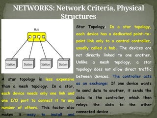
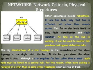
Star Topology: In a star topology,
each device has a dedicated point-to-
point link only to a central controller,
usually called a hub. The devices are
not directly linked to one another.
Unlike a mesh topology, a star
topology does not allow direct traffic
between devices. The controller acts
as an exchange: If one device wants
to send data to another, it sends the
data to the controller, which then
relays the data to the other
connected device .
A star topology is less expensive
than a mesh topology. In a star,
each device needs only one link and
one I/O port to connect it to any
number of others. This factor also
makes it easy to install and
21.
NETWORKS: Network Criteria,Physical
Structures
Other advantages include robustness.
If one link fails, only that link is
affected. All other links remain
active. This factor also lends itself to
easy fault identification and fault
isolation. As long as the hub is
working, it can be used to monitor link
problems and bypass defective links
One big disadvantage of a star topology is the dependency of the whole
topology on one single point, the hub. If the hub goes down, the whole
system is dead. Although a star requires far less cable than a mesh, each
node must be linked to a central hub. For this reason, often more cabling is
required in a star than in some other topologies (such as ring or bus).
22.
NETWORKS: Network Criteria,Physical
Structures
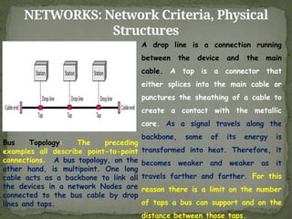
A drop line is a connection running
between the device and the main
cable. A tap is a connector that
either splices into the main cable or
punctures the sheathing of a cable to
create a contact with the metallic
core. As a signal travels along the
backbone, some of its energy is
transformed into heat. Therefore, it
becomes weaker and weaker as it
travels farther and farther. For this
reason there is a limit on the number
of taps a bus can support and on the
distance between those taps.
Bus Topology: The preceding
examples all describe point-to-point
connections. A bus topology, on the
other hand, is multipoint. One long
cable acts as a backbone to link all
the devices in a network Nodes are
connected to the bus cable by drop
lines and taps.
23.
NETWORKS: Network Criteria,Physical
Structures
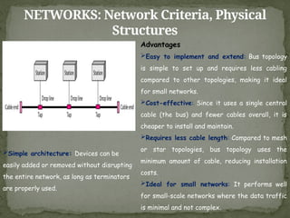
Advantages
Easy to implement and extend: Bus topology
is simple to set up and requires less cabling
compared to other topologies, making it ideal
for small networks.
Cost-effective: Since it uses a single central
cable (the bus) and fewer cables overall, it is
cheaper to install and maintain.
Requires less cable length: Compared to mesh
or star topologies, bus topology uses the
minimum amount of cable, reducing installation
costs.
Ideal for small networks: It performs well
for small-scale networks where the data traffic
is minimal and not complex.
Simple architecture: Devices can be
easily added or removed without disrupting
the entire network, as long as terminators
are properly used.
24.
NETWORKS: Network Criteria,Physical
Structures
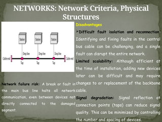
Disadvantages
Difficult fault isolation and reconnection:
Identifying and fixing faults in the central
bus cable can be challenging, and a single
fault can disrupt the entire network.
Limited scalability: Although efficient at
the time of installation, adding new devices
later can be difficult and may require
changes to or replacement of the backbone
cable.
Signal degradation: Signal reflection at
connection points (taps) can reduce signal
quality. This can be minimized by controlling
the number and spacing of devices.
Network failure risk: A break or fault in
the main bus line halts all network
communication, even between devices not
directly connected to the damaged
segment.
25.
NETWORKS: Network Criteria,Physical
Structures
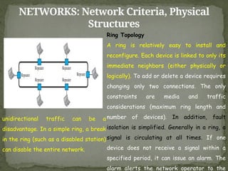
Ring Topology
A ring is relatively easy to install and
reconfigure. Each device is linked to only its
immediate neighbors (either physically or
logically). To add or delete a device requires
changing only two connections. The only
constraints are media and traffic
considerations (maximum ring length and
number of devices). In addition, fault
isolation is simplified. Generally in a ring, a
signal is circulating at all times. If one
device does not receive a signal within a
specified period, it can issue an alarm. The
alarm alerts the network operator to the
unidirectional traffic can be a
disadvantage. In a simple ring, a break
in the ring (such as a disabled station)
can disable the entire network.
26.
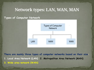
Network types: LAN,WAN, MAN
Types of Computer Network
There are mainly three types of computer networks based on their size:
1. Local Area Network (LAN) 2. Metropolitan Area Network (MAN)
3. Wide area network (WAN)
27.
Network types: LAN,WAN, MAN
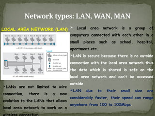
LOCAL AREA NETWORK (LAN) Local area network is a group of
computers connected with each other in a
small places such as school, hospital,
apartment etc.
LAN is secure because there is no outside
connection with the local area network thus
the data which is shared is safe on the
local area network and can’t be accessed
outside.
LAN due to their small size are
considerably faster, their speed can range
anywhere from 100 to 100Mbps.
LANs are not limited to wire
connection, there is a new
evolution to the LANs that allows
local area network to work on a
wireless connection
28.
Network types: LAN,WAN, MAN
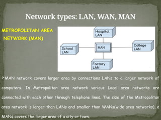
METROPOLITAN AREA
NETWORK (MAN)
MAN network covers larger area by connections LANs to a larger network of
computers. In Metropolitan area network various Local area networks are
connected with each other through telephone lines. The size of the Metropolitan
area network is larger than LANs and smaller than WANs(wide area networks), a
MANs covers the larger area of a city or town.
29.
Network types: LAN,WAN, MAN
WIDE AREA NETWORK (WAN)
A Wide Area Network (WAN) is also an interconnection of devices capable of
communication. However, there are some differences between a LAN and a WAN. A
LAN is normally limited in size, spanning an office, a building, or a campus; a
WAN has a wider geographical span, spanning a town, a state, a country, or
even the world. A LAN interconnects hosts; a WAN interconnects connecting
devices such as switches, routers, or modems. A LAN is normally privately
owned by the organization that uses it; a WAN is normally created and run by
communication companies and leased by an organization that uses it. We see two
distinct examples of WANs today: point-to-point WANs and switched WANs.
30.
Network types: LAN,WAN, MAN
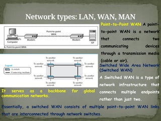
Point-to-Point WAN A point-
to-point WAN is a network
that connects two
communicating devices
through a transmission media
(cable or air).
Essentially, a switched WAN consists of multiple point-to-point WAN links
that are interconnected through network switches.
Switched Wide Area Network
(Switched WAN)
A Switched WAN is a type of
network infrastructure that
connects multiple endpoints
rather than just two.
It serves as a backbone for global
communication networks.
31.
INTERNETWORK
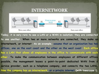
Today, it isvery rare to see a LAN or a WAN in isolation; they are connected
to one another. When two or more networks are connected, they make an
internetwork, or internet. As an example, assume that an organization has two
offices, one on the east coast and the other on the west coast. Each office
has a LAN that allows all employees in the office to communicate with each
other. To make the communication between employees at different offices
possible, the management leases a point-to-point dedicated WAN from a
service provider, such as a telephone company, and connects the two LANs.
Now the company has an internetwork, or a private internet (with lowercase i).
32.
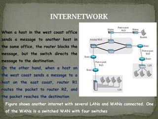
INTERNETWORK
When a hostin the west coast office
sends a message to another host in
the same office, the router blocks the
message, but the switch directs the
message to the destination.
On the other hand, when a host on
the west coast sends a message to a
host on the east coast, router R1
routes the packet to router R2, and
the packet reaches the destination
Figure shows another internet with several LANs and WANs connected. One
of the WANs is a switched WAN with four switches
33.
SWITCHING
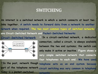
An internet isa switched network in which a switch connects at least two
links together. A switch needs to forward data from a network to another
network when required. The two most common types of switched networks
are Circuit-Switched Network and Packet-Switched Networks
Circuit-Switched Network In a circuit-switched network, a dedicated
connection, called a circuit, is always available
between the two end systems; the switch can
only make it active or inactive. Figure shows a
very simple switched network that connects
four telephones to each end. We have used
telephone sets as an end system because
circuit switching was very common in telephone
networks
In the past, network though
part of the telephone network
today is a packet-switched.
34.
SWITCHING
Circuit-Switched Network
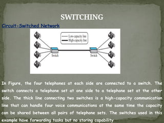
In Figure,the four telephones at each side are connected to a switch. The
switch connects a telephone set at one side to a telephone set at the other
side. The thick line connecting two switches is a high-capacity communication
line that can handle four voice communications at the same time the capacity
can be shared between all pairs of telephone sets. The switches used in this
example have forwarding tasks but no storing capability
35.
SWITCHING
Circuit-Switched Network
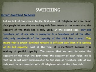
Let uslook at two cases. In the first case, all telephone sets are busy;
four people at one site are talking with four people at the other site; the
capacity of the thick line is fully used. In the second case, only one
telephone set at one side is connected to a telephone set at the other
side; only one-fourth of the capacity of the thick line is used. This
means that a circuit-switched network is efficient only when it is working
at its full capacity; most of the time, it is inefficient because it is
working at partial capacity. The reason that we need to make the
capacity of the thick line four times the capacity of each voice line is
that we do not want communication to fail when all telephone sets at one
side want to be connected with all telephone sets at the other side.
36.
SWITCHING
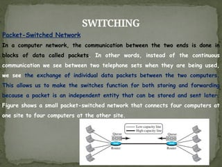
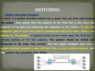
Packet-Switched Network
In acomputer network, the communication between the two ends is done in
blocks of data called packets. In other words, instead of the continuous
communication we see between two telephone sets when they are being used,
we see the exchange of individual data packets between the two computers.
This allows us to make the switches function for both storing and forwarding
because a packet is an independent entity that can be stored and sent later.
Figure shows a small packet-switched network that connects four computers at
one site to four computers at the other site.
37.
SWITCHING
Packet-Switched Network
A routerin a packet-switched network has a queue that can store and forward
the packet. Now assume that the capacity of the thick line is only twice the
capacity of the data line connecting the computers to the routers. If only two
computers (one at each site) need to communicate with each other, there is no
waiting for the packets. if packets arrive at one router when the thick line is
already working at its full capacity, the packets should be stored and
forwarded in the order they arrived. The two simple examples show that a
packet-switched network is more efficient than a circuit switched network, but
the packets may encounter some delays.
38.
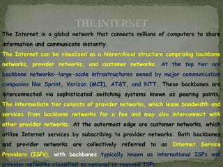
THE INTERNET
The Internetis a global network that connects millions of computers to share
information and communicate instantly.
The Internet can be visualized as a hierarchical structure comprising backbone
networks, provider networks, and customer networks. At the top tier are
backbone networks—large-scale infrastructures owned by major communication
companies like Sprint, Verizon (MCI), AT&T, and NTT. These backbones are
interconnected via sophisticated switching systems known as peering points.
The intermediate tier consists of provider networks, which lease bandwidth and
services from backbone networks for a fee and may also interconnect with
other provider networks. At the outermost edge are customer networks, which
utilize Internet services by subscribing to provider networks. Both backbones
and provider networks are collectively referred to as Internet Service
Providers (ISPs), with backbones typically known as international ISPs and
provider networks classified as national or regional ISPs.
39.
THE INTERNET
The Internetis a global network that connects millions of computers to share
information and communicate instantly.
The Internet can be visualized as a hierarchical structure comprising backbone
networks, provider networks, and customer networks. At the top tier are
backbone networks—large-scale infrastructures owned by major communication
companies like Sprint, Verizon (MCI), AT&T, and NTT. These backbones are
interconnected via sophisticated switching systems known as peering points.
The intermediate tier consists of provider networks, which lease bandwidth and
services from backbone networks for a fee and may also interconnect with
other provider networks. At the outermost edge are customer networks, which
utilize Internet services by subscribing to provider networks. Both backbones
and provider networks are collectively referred to as Internet Service
Providers (ISPs), with backbones typically known as international ISPs and
provider networks classified as national or regional ISPs.
40.
NETWORK MODELS
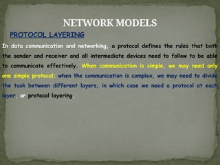
In datacommunication and networking, a protocol defines the rules that both
the sender and receiver and all intermediate devices need to follow to be able
to communicate effectively. When communication is simple, we may need only
one simple protocol; when the communication is complex, we may need to divide
the task between different layers, in which case we need a protocol at each
layer, or protocol layering.
PROTOCOL LAYERING
41.
NETWORK MODELS
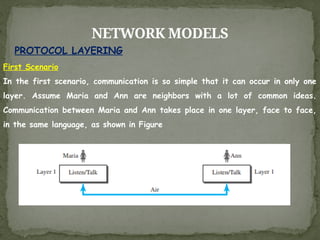
First Scenario
Inthe first scenario, communication is so simple that it can occur in only one
layer. Assume Maria and Ann are neighbors with a lot of common ideas.
Communication between Maria and Ann takes place in one layer, face to face,
in the same language, as shown in Figure
PROTOCOL LAYERING
42.
NETWORK MODELS
Even inthis simple scenario, we can see that a set of rules needs to be
followed. First, Maria and Ann know that they should greet each other when
they meet. Second, they know that they should confine their vocabulary to the
level of their friendship. Third, each party knows that she should refrain from
speaking when the other party is speaking. Fourth, each party knows that the
conversation should be a dialog, not a monolog: both should have the
opportunity to talk about the issue. Fifth, they should exchange some nice
words when they leave. We can see that the protocol used by Maria and Ann
is different from the communication between a professor and the students in a
lecture hall. The communication in the second case is mostly monolog; the
professor talks most of the time unless a student has a question, a situation in
which the protocol dictates that she should raise her hand and wait for
permission to speak. In this case, the communication is normally very formal
and limited to the subject being taught.
43.
NETWORK MODELS
Second ScenarioIn the second scenario, we assume that Ann is offered a
higher-level position in her company, but needs to move to another branch
located in a city very far from Maria. The two friends still want to continue
their communication and exchange ideas because they have come up with an
innovative project to start a new business when they both retire. They decide
to continue their conversation using regular mail through the post office.
However, they do not want their ideas to be revealed by other people if the
letters are intercepted. They agree on an encryption/decryption technique.
The sender of the letter encrypts it to make it unreadable by an intruder; the
receiver of the letter decrypts it to get the original letter
PROTOCOL LAYERING
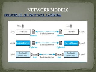
NETWORK MODELS
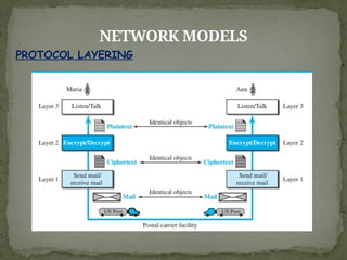
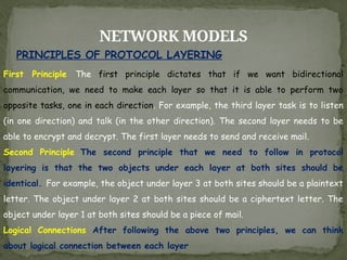
PRINCIPLES OFPROTOCOL LAYERING
First Principle The first principle dictates that if we want bidirectional
communication, we need to make each layer so that it is able to perform two
opposite tasks, one in each direction. For example, the third layer task is to listen
(in one direction) and talk (in the other direction). The second layer needs to be
able to encrypt and decrypt. The first layer needs to send and receive mail.
Second Principle The second principle that we need to follow in protocol
layering is that the two objects under each layer at both sites should be
identical. For example, the object under layer 3 at both sites should be a plaintext
letter. The object under layer 2 at both sites should be a ciphertext letter. The
object under layer 1 at both sites should be a piece of mail.
Logical Connections After following the above two principles, we can think
about logical connection between each layer
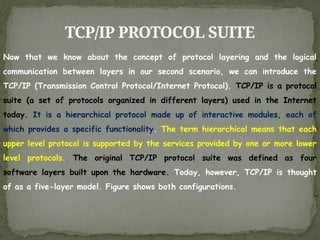
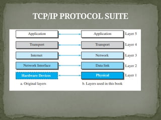
TCP/IP PROTOCOL SUITE
Nowthat we know about the concept of protocol layering and the logical
communication between layers in our second scenario, we can introduce the
TCP/IP (Transmission Control Protocol/Internet Protocol). TCP/IP is a protocol
suite (a set of protocols organized in different layers) used in the Internet
today. It is a hierarchical protocol made up of interactive modules, each of
which provides a specific functionality. The term hierarchical means that each
upper level protocol is supported by the services provided by one or more lower
level protocols. The original TCP/IP protocol suite was defined as four
software layers built upon the hardware. Today, however, TCP/IP is thought
of as a five-layer model. Figure shows both configurations.
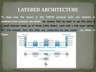
LAYERED ARCHITECTURE
To showhow the layers in the TCP/IP protocol suite are involved in
communication between two hosts, we assume that we want to use the suite in
a small internet made up of three LANs (links), each with a link-layer switch.
We also assume that the links are connected by one router, as shown in
Figure.
50.
LAYERED ARCHITECTURE
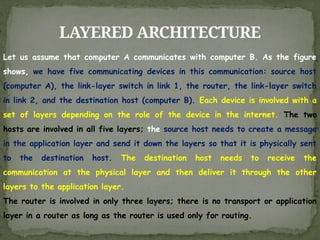
Let usassume that computer A communicates with computer B. As the figure
shows, we have five communicating devices in this communication: source host
(computer A), the link-layer switch in link 1, the router, the link-layer switch
in link 2, and the destination host (computer B). Each device is involved with a
set of layers depending on the role of the device in the internet. The two
hosts are involved in all five layers; the source host needs to create a message
in the application layer and send it down the layers so that it is physically sent
to the destination host. The destination host needs to receive the
communication at the physical layer and then deliver it through the other
layers to the application layer.
The router is involved in only three layers; there is no transport or application
layer in a router as long as the router is used only for routing.
51.
LAYERED ARCHITECTURE
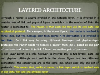
Although arouter is always involved in one network layer, it is involved in n
combinations of link and physical layers in which n is the number of links the
router is connected to. The reason is that each link may use its own data-link
or physical protocol. For example, in the above figure, the router is involved in
three links, but the message sent from source A to destination B is involved in
two links. Each link may be using different link-layer and physical-layer
protocols; the router needs to receive a packet from link 1 based on one pair
of protocols and deliver it to link 2 based on another pair of protocols.
A link-layer switch in a link, however, is involved only in two layers, data-link
and physical. Although each switch in the above figure has two different
connections, the connections are in the same link, which uses only one set of
protocols. This means that, unlike a router, a link-layer switch is involved only
in one data-link and one physical layer.
52.
LAYERS IN THETCP/IP PROTOCOL
SUITE
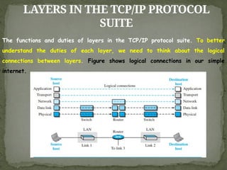
The functions and duties of layers in the TCP/IP protocol suite. To better
understand the duties of each layer, we need to think about the logical
connections between layers. Figure shows logical connections in our simple
internet.
53.
LAYERS IN THETCP/IP PROTOCOL
SUITE
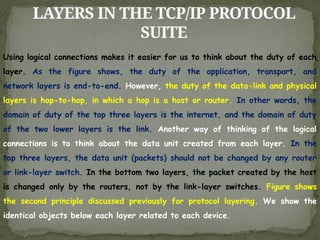
Using logical connections makes it easier for us to think about the duty of each
layer. As the figure shows, the duty of the application, transport, and
network layers is end-to-end. However, the duty of the data-link and physical
layers is hop-to-hop, in which a hop is a host or router. In other words, the
domain of duty of the top three layers is the internet, and the domain of duty
of the two lower layers is the link. Another way of thinking of the logical
connections is to think about the data unit created from each layer. In the
top three layers, the data unit (packets) should not be changed by any router
or link-layer switch. In the bottom two layers, the packet created by the host
is changed only by the routers, not by the link-layer switches. Figure shows
the second principle discussed previously for protocol layering. We show the
identical objects below each layer related to each device.
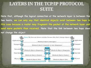
54.
LAYERS IN THETCP/IP PROTOCOL
SUITE
Note that, although the logical connection at the network layer is between the
two hosts, we can only say that identical objects exist between two hops in
this case because a router may fragment the packet at the network layer and
send more packets than received. Note that the link between two hops does
not change the object
55.
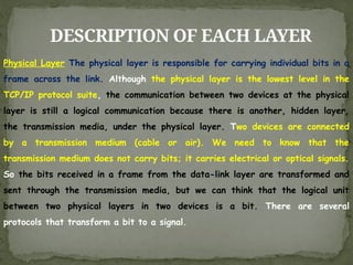
DESCRIPTION OF EACHLAYER
Physical Layer The physical layer is responsible for carrying individual bits in a
frame across the link. Although the physical layer is the lowest level in the
TCP/IP protocol suite, the communication between two devices at the physical
layer is still a logical communication because there is another, hidden layer,
the transmission media, under the physical layer. Two devices are connected
by a transmission medium (cable or air). We need to know that the
transmission medium does not carry bits; it carries electrical or optical signals.
So the bits received in a frame from the data-link layer are transformed and
sent through the transmission media, but we can think that the logical unit
between two physical layers in two devices is a bit. There are several
protocols that transform a bit to a signal.
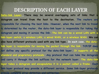
56.
DESCRIPTION OF EACHLAYER
Data-link Layer: There may be several overlapping sets of links that a
datagram can travel from the host to the destination. The routers are
responsible for choosing the best links. However, when the next link to travel
is determined by the router, the data-link layer is responsible for taking the
datagram and moving it across the link. The link can be a wired LAN with a
link-layer switch, a wireless LAN, a wired WAN, or a wireless WAN. We can
also have different protocols used with any link type. In each case, the data-
link layer is responsible for moving the packet through the link. TCP/IP does
not define any specific protocol for the data-link layer. It supports all the
standard and proprietary protocols. Any protocol that can take the datagram
and carry it through the link suffices for the network layer. The data-link
layer takes a datagram and encapsulates it in a packet called a frame. Each
link-layer protocol may provide a different service. Some link-layer protocols
provide complete error detection and correction.
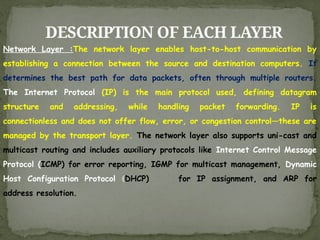
57.
DESCRIPTION OF EACHLAYER
Network Layer :The network layer enables host-to-host communication by
establishing a connection between the source and destination computers. It
determines the best path for data packets, often through multiple routers.
The Internet Protocol (IP) is the main protocol used, defining datagram
structure and addressing, while handling packet forwarding. IP is
connectionless and does not offer flow, error, or congestion control—these are
managed by the transport layer. The network layer also supports uni-cast and
multicast routing and includes auxiliary protocols like Internet Control Message
Protocol (ICMP) for error reporting, IGMP for multicast management, Dynamic
Host Configuration Protocol (DHCP) for IP assignment, and ARP for
address resolution.
58.
DESCRIPTION OF EACHLAYER
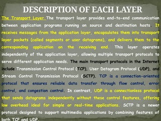
The Transport Layer The transport layer provides end-to-end communication
between application programs running on source and destination hosts. It
receives messages from the application layer, encapsulates them into transport
layer packets (called segments or user datagrams), and delivers them to the
corresponding application on the receiving end. This layer operates
independently of the application layer, allowing multiple transport protocols to
serve different application needs. The main transport protocols in the Internet
include Transmission Control Protocol (TCP), User Datagram Protocol (UDP), and
Stream Control Transmission Protocol (SCTP). TCP is a connection-oriented
protocol that ensures reliable data transfer through flow control, error
control, and congestion control. In contrast, UDP is a connectionless protocol
that sends datagrams independently without these control features, offering
low overhead ideal for simple or real-time applications. SCTP is a newer
protocol designed to support multimedia applications by combining features of
both TCP and UDP.
59.
DESCRIPTION OF EACHLAYER
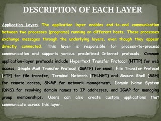
Application Layer: The application layer enables end-to-end communication
between two processes (programs) running on different hosts. These processes
exchange messages through the underlying layers, even though they appear
directly connected. This layer is responsible for process-to-process
communication and supports various predefined Internet protocols. Common
application-layer protocols include Hypertext Transfer Protocol (HTTP) for web
access, Simple Mail Transfer Protocol (SMTP) for email, File Transfer Protocol
(FTP) for file transfer, Terminal Network (TELNET) and Secure Shell (SSH)
for remote access, SNMP for network management, Domain Name System
(DNS) for resolving domain names to IP addresses, and IGMP for managing
group memberships. Users can also create custom applications that
communicate across this layer.
60.
ENCAPSULATION AND
DECAPSULATION
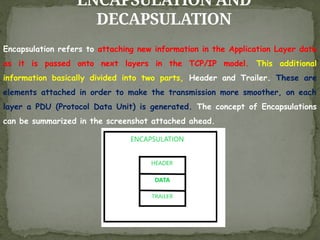
Encapsulation refersto attaching new information in the Application Layer data
as it is passed onto next layers in the TCP/IP model. This additional
information basically divided into two parts, Header and Trailer. These are
elements attached in order to make the transmission more smoother, on each
layer a PDU (Protocol Data Unit) is generated. The concept of Encapsulations
can be summarized in the screenshot attached ahead.
61.
ENCAPSULATION AND
DECAPSULATION
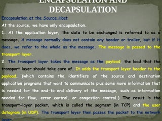
Encapsulation atthe Source Host
At the source, we have only encapsulation.
1. At the application layer, the data to be exchanged is referred to as a
message. A message normally does not contain any header or trailer, but if it
does, we refer to the whole as the message. The message is passed to the
transport layer.
2. The transport layer takes the message as the payload, the load that the
transport layer should take care of. It adds the transport layer header to the
payload, (which contains the identifiers of the source and destination
application programs that want to communicate plus some more information that
is needed for the end-to end delivery of the message, such as information
needed for flow, error control, or congestion control.) The result is the
transport-layer packet, which is called the segment (in TCP) and the user
datagram (in UDP). The transport layer then passes the packet to the network
layer.
62.
ENCAPSULATION AND
DECAPSULATION
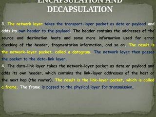
3. Thenetwork layer takes the transport-layer packet as data or payload and
adds its own header to the payload. The header contains the addresses of the
source and destination hosts and some more information used for error
checking of the header, fragmentation information, and so on. The result is
the network-layer packet, called a datagram. The network layer then passes
the packet to the data-link layer.
4. The data-link layer takes the network-layer packet as data or payload and
adds its own header, which contains the link-layer addresses of the host or
the next hop (the router). The result is the link-layer packet, which is called
a frame. The frame is passed to the physical layer for transmission.
63.
ENCAPSULATION AND
DECAPSULATION
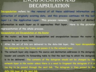
Decapsulation refersto the removal of all these additional information and
extraction of originally existing data, and this process continues till the last
layer i.e. the Application Layer. This process removes, fragments of distinct
information in each layer as it approaches that layer. Here is the pictorial
representation of the whole process.
Decapsulation and Encapsulation at the Router
At the router, we have both decapsulation and encapsulation because the router is
connected to two or more links.
1. After the set of bits are delivered to the data-link layer, this layer decapsulates
the datagram from the frame and passes it to the network layer.
2. The network layer only inspects the source and destination addresses in the datagram
header and consults its forwarding table to find the next hop to which the datagram
is to be delivered. The contents of the datagram should not be changed by the
network layer in the router unless there is a need to fragment the datagram if it is
too big to be passed through the next link. The datagram is then passed to the
data-link layer of the next link.
64.
ENCAPSULATION AND
DECAPSULATION
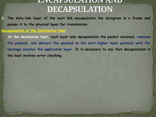
3. Thedata-link layer of the next link encapsulates the datagram in a frame and
passes it to the physical layer for transmission.
Decapsulation at the Destination Host
At the destination host, each layer only decapsulates the packet received, removes
the payload, and delivers the payload to the next-higher layer protocol until the
message reaches the application layer. It is necessary to say that decapsulation in
the host involves error checking.
65.
MULTIPLEXING AND
DEMULTIPLEXING
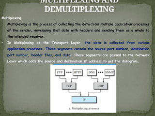
Multiplexing
• Multiplexingis the process of collecting the data from multiple application processes
of the sender, enveloping that data with headers and sending them as a whole to
the intended receiver.
• In Multiplexing at the Transport Layer, the data is collected from various
application processes. These segments contain the source port number, destination
port number, header files, and data. These segments are passed to the Network
Layer which adds the source and destination IP address to get the datagram.
66.
MULTIPLEXING AND
DEMULTIPLEXING
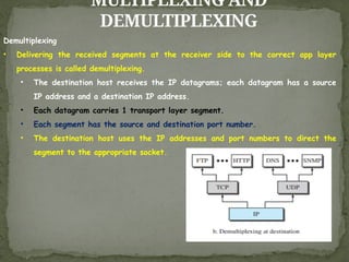
Demultiplexing
• Deliveringthe received segments at the receiver side to the correct app layer
processes is called demultiplexing.
• The destination host receives the IP datagrams; each datagram has a source
IP address and a destination IP address.
• Each datagram carries 1 transport layer segment.
• Each segment has the source and destination port number.
• The destination host uses the IP addresses and port numbers to direct the
segment to the appropriate socket.
67.
ADDRESSING
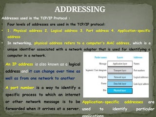
Addresses used inthe TCP/IP Protocol :
• Four levels of addresses are used in the TCP/IP protocol:
• 1. Physical address 2. Logical address 3. Port address 4. Application-specific
address
• In networking, physical address refers to a computer's MAC address, which is a
unique identifier associated with a network adapter that is used for identifying a
computer in a network.
An IP address is also known as a logical
address and it can change over time as
well as from one network to another
A port number is a way to identify a
specific process to which an internet
or other network message is to be
forwarded when it arrives at a server.
Application-specific addresses are
used to identify particular
68.
ADDRESSING
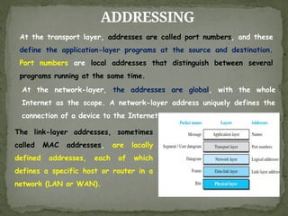
The link-layer addresses,sometimes
called MAC addresses, are locally
defined addresses, each of which
defines a specific host or router in a
network (LAN or WAN).
At the transport layer, addresses are called port numbers, and these
define the application-layer programs at the source and destination.
Port numbers are local addresses that distinguish between several
programs running at the same time.
At the network-layer, the addresses are global, with the whole
Internet as the scope. A network-layer address uniquely defines the
connection of a device to the Internet.
69.
OSI MODEL
Established in1947, the International Organization for Standardization
(ISO) is a Multinational Body dedicated to worldwide agreement on
international standards. Almost three-fourths of the countries in the
world are represented in the ISO. An ISO standard that covers all
aspects of network communications is the Open Systems Interconnection
(OSI) model. It was first introduced in the late 1970s
An open system is a set of protocols that allows any two different systems to
communicate regardless of their underlying architecture. The purpose of the
OSI model is to show how to facilitate communication between different
systems without requiring changes to the logic of the underlying hardware and
software.
The OSI model is not a protocol it is a model for understanding and designing
a network architecture that is flexible, robust, and interoperable. The OSI
model was intended to be the basis for the creation of the protocols in the
OSI stack.
70.
OSI MODEL
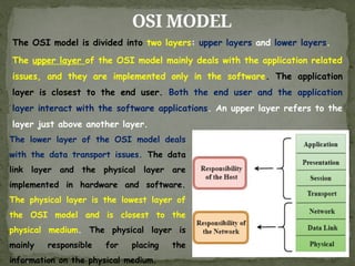
The OSImodel is divided into two layers: upper layers and lower layers.
The upper layer of the OSI model mainly deals with the application related
issues, and they are implemented only in the software. The application
layer is closest to the end user. Both the end user and the application
layer interact with the software applications. An upper layer refers to the
layer just above another layer.
The lower layer of the OSI model deals
with the data transport issues. The data
link layer and the physical layer are
implemented in hardware and software.
The physical layer is the lowest layer of
the OSI model and is closest to the
physical medium. The physical layer is
mainly responsible for placing the
information on the physical medium.
71.
OSI VS TCP/IP
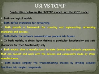
Similaritiesbetween the TCP/IP model and the OSI model
Both are logical models.
Both define standards for networking.
Both provide a framework for creating and implementing networking
standards and devices.
Both divide the network communication process into layers.
In both models, a single layer defines a particular functionality and sets
standards for that functionality only.
Both models allow a manufacturer to make devices and network components
that can coexist and work with the devices and components made by other
manufacturers.
Both models simplify the troubleshooting process by dividing complex
functions into simpler components.
72.
OSI VS TCP/IP
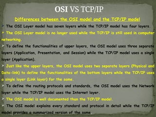
Differencesbetween the OSI model and the TCP/IP model
The OSI Layer model has seven layers while the TCP/IP model has four layers.
The OSI Layer model is no longer used while the TCP/IP is still used in computer
networking.
To define the functionalities of upper layers, the OSI model uses three separate
layers (Application, Presentation, and Session) while the TCP/IP model uses a single
layer (Application).
Just like the upper layers, the OSI model uses two separate layers (Physical and
Data-link) to define the functionalities of the bottom layers while the TCP/IP uses
a single layer (Link layer) for the same.
To define the routing protocols and standards, the OSI model uses the Network
layer while the TCP/IP model uses the Internet layer.
The OSI model is well documented than the TCP/IP model.
The OSI model explains every standard and protocol in detail while the TCP/IP
model provides a summarized version of the same.
73.
OSI VS TCP/IP
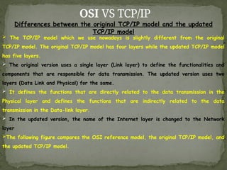
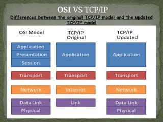
Differencesbetween the original TCP/IP model and the updated
TCP/IP model
The TCP/IP model which we use nowadays is slightly different from the original
TCP/IP model. The original TCP/IP model has four layers while the updated TCP/IP model
has five layers.
The original version uses a single layer (Link layer) to define the functionalities and
components that are responsible for data transmission. The updated version uses two
layers (Data Link and Physical) for the same.
It defines the functions that are directly related to the data transmission in the
Physical layer and defines the functions that are indirectly related to the data
transmission in the Data-link layer.
In the updated version, the name of the Internet layer is changed to the Network
layer
The following figure compares the OSI reference model, the original TCP/IP model, and
the updated TCP/IP model.
DATA-LINK LAYER
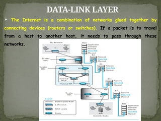
TheInternet is a combination of networks glued together by
connecting devices (routers or switches). If a packet is to travel
from a host to another host, it needs to pass through these
networks.
76.
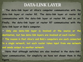
DATA-LINK LAYER
Thedata-link layer at Alice’s computer communicates with the
data-link layer at router R2. The data-link layer at router R2
communicates with the data-link layer at router R4, and so on.
Finally, the data-link layer at router R7 communicates with the
data-link layer at Bob’s computer.
Only one data-link layer is involved at the source or the
destination, but two data-link layers are involved at each router.
The reason is that Alice’s and Bob’s computers are each connected
to a single network, but each router takes input from one network
and sends output to another network.
Note that although switches are also involved in the data-link-
layer communication, for simplicity we have not shown them in the
figure.
77.
NODES AND LINKS
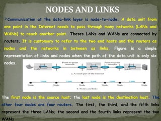
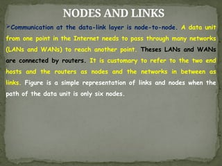
Communicationat the data-link layer is node-to-node. A data unit from
one point in the Internet needs to pass through many networks (LANs and
WANs) to reach another point. Theses LANs and WANs are connected by
routers. It is customary to refer to the two end hosts and the routers as
nodes and the networks in between as links. Figure is a simple
representation of links and nodes when the path of the data unit is only six
nodes.
The first node is the source host; the last node is the destination host. The
other four nodes are four routers. The first, the third, and the fifth links
represent the three LANs; the second and the fourth links represent the two
WANs
78.
NODES AND LINKS
Communicationat the data-link layer is node-to-node. A data unit
from one point in the Internet needs to pass through many networks
(LANs and WANs) to reach another point. Theses LANs and WANs
are connected by routers. It is customary to refer to the two end
hosts and the routers as nodes and the networks in between as
links. Figure is a simple representation of links and nodes when the
path of the data unit is only six nodes.
79.
SERVICES
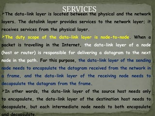
The data-link layeris located between the physical and the network
layers. The datalink layer provides services to the network layer; it
receives services from the physical layer.
The duty scope of the data-link layer is node-to-node. When a
packet is travelling in the Internet, the data-link layer of a node
(host or router) is responsible for delivering a datagram to the next
node in the path. For this purpose, the data-link layer of the sending
node needs to encapsulate the datagram received from the network in
a frame, and the data-link layer of the receiving node needs to
decapsulate the datagram from the frame.
In other words, the data-link layer of the source host needs only
to encapsulate, the data-link layer of the destination host needs to
decapsulate, but each intermediate node needs to both encapsulate
and decapsulate.
80.
SERVICES
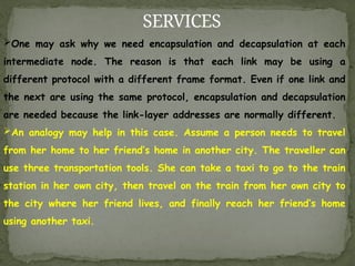
One may askwhy we need encapsulation and decapsulation at each
intermediate node. The reason is that each link may be using a
different protocol with a different frame format. Even if one link and
the next are using the same protocol, encapsulation and decapsulation
are needed because the link-layer addresses are normally different.
An analogy may help in this case. Assume a person needs to travel
from her home to her friend’s home in another city. The traveller can
use three transportation tools. She can take a taxi to go to the train
station in her own city, then travel on the train from her own city to
the city where her friend lives, and finally reach her friend’s home
using another taxi.
81.
SERVICES
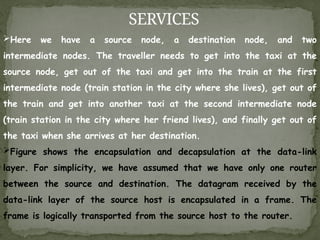
Here we havea source node, a destination node, and two
intermediate nodes. The traveller needs to get into the taxi at the
source node, get out of the taxi and get into the train at the first
intermediate node (train station in the city where she lives), get out of
the train and get into another taxi at the second intermediate node
(train station in the city where her friend lives), and finally get out of
the taxi when she arrives at her destination.
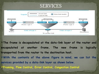
Figure shows the encapsulation and decapsulation at the data-link
layer. For simplicity, we have assumed that we have only one router
between the source and destination. The datagram received by the
data-link layer of the source host is encapsulated in a frame. The
frame is logically transported from the source host to the router.
82.
SERVICES
The frame isdecapsulated at the data-link layer of the router and
encapsulated at another frame. The new frame is logically
transported from the router to the destination host.
With the contents of the above figure in mind, we can list the
services provided by a data-link layer as shown below.
Framing, Flow Control, Error Control, Congestion Control
83.
SERVICES
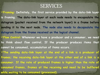
Framing: Definitely, thefirst service provided by the data-link layer
is framing. The data-link layer at each node needs to encapsulate the
datagram (packet received from the network layer) in a frame before
sending it to the next node. The node also needs to decapsulate the
datagram from the frame received on the logical channel.
Flow Control: Whenever we have a producer and a consumer, we need
to think about flow control. If the producer produces items that
cannot be consumed, accumulation of items occurs.
The sending data-link layer at the end of a link is a producer of
frames; the receiving data-link layer at the other end of a link is a
consumer. If the rate of produced frames is higher than the rate of
consumed frames, frames at the receiving end need to be buffered
while waiting to be consumed (processed).
84.
SERVICES
Definitely, we cannothave an unlimited buffer size at the receiving
side. We have two choices. The first choice is to let the receiving
data-link layer drop the frames if its buffer is full. The second choice
is to let the receiving data-link layer send a feedback to the sending
data-link layer to ask it to stop or slow down.
Error Control: At the sending node, a frame in a data-link layer
needs to be changed to bits, transformed to electromagnetic signals,
and transmitted through the transmission media. At the receiving node,
electromagnetic signals are received, transformed to bits, and put
together to create a frame. Since electromagnetic signals are
susceptible to error, a frame is susceptible to error. The error needs
first to be detected. After detection, it needs to be either corrected
at the receiver node or discarded and retransmitted by the sending
node
85.
SERVICES
Congestion Control: Althougha link may be congested with frames,
which may result in frame loss, most data-link-layer protocols do not
directly use a congestion control to alleviate congestion, although some
wide-area networks do. In general, congestion control is considered an
issue in the network layer or the transport layer because of its end-
to-end nature
86.
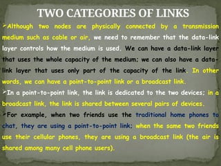
TWO CATEGORIES OFLINKS
Although two nodes are physically connected by a transmission
medium such as cable or air, we need to remember that the data-link
layer controls how the medium is used. We can have a data-link layer
that uses the whole capacity of the medium; we can also have a data-
link layer that uses only part of the capacity of the link. In other
words, we can have a point-to-point link or a broadcast link.
In a point-to-point link, the link is dedicated to the two devices; in a
broadcast link, the link is shared between several pairs of devices.
For example, when two friends use the traditional home phones to
chat, they are using a point-to-point link; when the same two friends
use their cellular phones, they are using a broadcast link (the air is
shared among many cell phone users).
87.
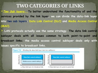
TWO CATEGORIES OFLINKS
Two Sub layers: To better understand the functionality of and the
services provided by the link layer, we can divide the data-link layer
into two sub layers: Data Link Control (DLC) and Media Access Control
(MAC).
LAN protocols actually use the same strategy. The data link control
sublayer deals with all issues common to both point-to-point and
broadcast links; the media access control sublayer deals only with
issues specific to broadcast links.
88.
LINK-LAYER ADDRESSING
The nextissue we need to discuss about the data-link layer is the
link-layer addresses. IP addresses as the identifiers at the network
layer that define the exact points in the Internet where the source
and destination hosts are connected. However, in a connectionless
internetwork such as the Internet we cannot make a datagram reach
its destination using only IP addresses. The reason is that each
datagram in the Internet, from the same source host to the same
destination host, may take a different path. The source and
destination IP addresses define the two ends but cannot define which
links the datagram should pass through. We need to remember that
the IP addresses in a datagram should not be changed. If the
destination IP address in a datagram changes, the packet never
reaches its destination;
89.
LINK-LAYER ADDRESSING
If thesource IP address in a datagram changes, the destination host
or a router can never communicate with the source if a response needs
to be sent back or an error needs to be reported back to the source.
The above discussion shows that we need another addressing
mechanism in a connectionless internetwork: the link-layer addresses of
the two nodes. A link-layer address is sometimes called a link address,
sometimes a physical address, and sometimes a MAC address
Since a link is controlled at the data-link layer, the addresses need
to belong to the data-link layer. When a datagram passes from the
network layer to the data-link layer, the datagram will be
encapsulated in a frame and two data-link addresses are added to the
frame header. These two addresses are changed every time the frame
moves from one link to another.
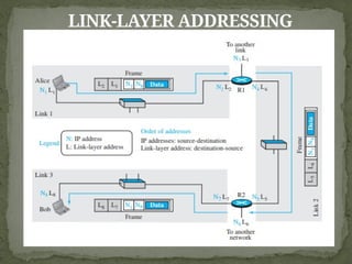
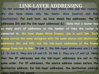
LINK-LAYER ADDRESSING
In theinternet in Figure 9.5, we have three links and two routers.
We also have shown only two hosts: Alice (source) and Bob
(destination). For each host, we have shown two addresses, the IP
addresses (N) and the link-layer addresses (L). Note that a router has
as many pairs of addresses as the number of links the router is
connected to. We have shown three frames, one in each link. Each
frame carries the same datagram with the same source and destination
addresses (N1 and N8), but the link-layer addresses of the frame
change from link to link. In link 1, the link-layer addresses are L1 and
L2. In link 2, they are L4 and L5. In link 3, they are L7 and L8. Note
that the IP addresses and the link-layer addresses are not in the
same order. For IP addresses, the source address comes before the
destination address; for link-layer addresses, the destination address
comes before the source.
92.
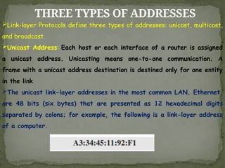
THREE TYPES OFADDRESSES
Link-layer Protocols define three types of addresses: unicast, multicast,
and broadcast.
Unicast Address: Each host or each interface of a router is assigned
a unicast address. Unicasting means one-to-one communication. A
frame with a unicast address destination is destined only for one entity
in the link
The unicast link-layer addresses in the most common LAN, Ethernet,
are 48 bits (six bytes) that are presented as 12 hexadecimal digits
separated by colons; for example, the following is a link-layer address
of a computer.
93.
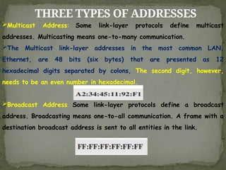
THREE TYPES OFADDRESSES
Multicast Address: Some link-layer protocols define multicast
addresses. Multicasting means one-to-many communication.
The Multicast link-layer addresses in the most common LAN,
Ethernet, are 48 bits (six bytes) that are presented as 12
hexadecimal digits separated by colons, The second digit, however,
needs to be an even number in hexadecimal.
Broadcast Address Some link-layer protocols define a broadcast
address. Broadcasting means one-to-all communication. A frame with a
destination broadcast address is sent to all entities in the link.
94.
ADDRESS RESOLUTION PROTOCOL
(ARP)
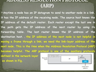
Anytimea node has an IP datagram to send to another node in a link,
it has the IP address of the receiving node. The source host knows the
IP address of the default router. Each router except the last one in
the path gets the IP address of the next router by using its
forwarding table. The last router knows the IP address of the
destination host. , the IP address of the next node is not helpful in
moving a frame through a link; we need the link-layer address of the
next node. This is the time when the Address Resolution Protocol (ARP)
becomes helpful. The ARP protocol is one of the auxiliary protocols
defined in the network layer
as shown in Fig.
95.
ADDRESS RESOLUTION PROTOCOL
(ARP)
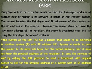
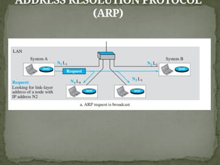
Anytimea host or a router needs to find the link-layer address of
another host or router in its network, it sends an ARP request packet.
The packet includes the link-layer and IP addresses of the sender and
the IP address of the receiver. Because the sender does not know the
link-layer address of the receiver, the query is broadcast over the link
using the link-layer broadcast address
the system on the left (A) has a packet that needs to be delivered
to another system (B) with IP address N2. System A needs to pass
the packet to its data-link layer for the actual delivery, but it does
not know the physical address of the recipient. It uses the services of
ARP by asking the ARP protocol to send a broadcast ARP request
packet to ask for the physical address of a system with an IP address
of N2
ADDRESS RESOLUTION PROTOCOL
(ARP)
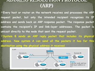
Everyhost or router on the network receives and processes the ARP
request packet, but only the intended recipient recognizes its IP
address and sends back an ARP response packet. The response packet
contains the recipient’s IP and link-layer addresses. The packet is
unicast directly to the node that sent the request packet.
System B sends an ARP reply packet that includes its physical
address. Now system A can send all the packets it has for this
destination using the physical address it received
98.
ADDRESS RESOLUTION PROTOCOL
(ARP)
Caching:A question that is often asked is this: If system A can
broadcast a frame to find the link layer address of system B, why
can’t system A send the datagram for system B using a broadcast
frame? In other words, instead of sending one broadcast frame (ARP
request), one unicast frame (ARP response), and another unicast frame
(for sending the datagram), system A can encapsulate the datagram
and send it to the network. System B receives it and keep it; other
systems discard it. To answer the question, we need to think about the
efficiency. It is probable that system A has more than one datagram
to send to system B in a short period of time. For example, if system
B is supposed to receive a long e-mail or a long file, the data do not
fit in one datagram.
99.
ADDRESS RESOLUTION PROTOCOL
(ARP)
Letus assume that there are 20 systems connected to the network
(link): system A, system B, and 18 other systems. We also assume
that system A has 10 datagrams to send to system B in one second.
Without using ARP, system A needs to send 10 broadcast frames.
Each of the 18 other systems need to receive the frames, decapsulate
the frames, remove the datagram and pass it to their network-layer
to find out the datagrams do not belong to them.This means processing
and discarding 180 broadcast frames.
100.
ADDRESS RESOLUTION PROTOCOL
(ARP)
UsingARP, system A needs to send only one broadcast frame. Each
of the 18 other systems need to receive the frames, decapsulate the
frames, remove the ARP message and pass the message to their ARP
protocol to find that the frame must be discarded. This means
processing and discarding only 18 (instead of 180) broadcast frames.
After system B responds with its own data-link address, system A can
store the link-layer address in its cache memory. The rest of the nine
frames are only unicast.
101.
ADDRESS RESOLUTION PROTOCOL
(ARP)
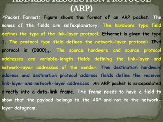
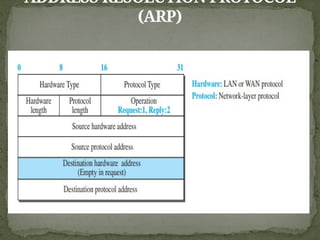
PacketFormat: Figure shows the format of an ARP packet. The
names of the fields are selfexplanatory. The hardware type field
defines the type of the link-layer protocol; Ethernet is given the type
1. The protocol type field defines the network-layer protocol: IPv4
protocol is (0800)16. The source hardware and source protocol
addresses are variable-length fields defining the link-layer and
network-layer addresses of the sender. The destination hardware
address and destination protocol address fields define the receiver
link-layer and network-layer addresses. An ARP packet is encapsulated
directly into a data-link frame. The frame needs to have a field to
show that the payload belongs to the ARP and not to the network-
layer datagram.