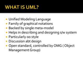
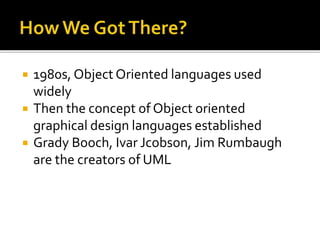
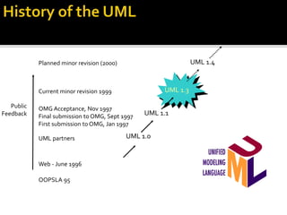
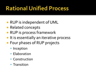
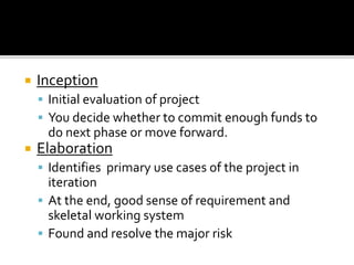
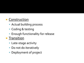
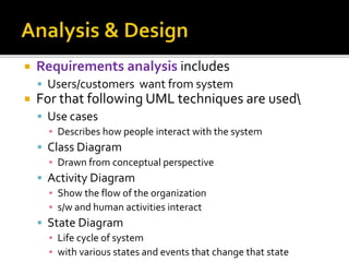
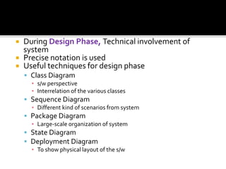
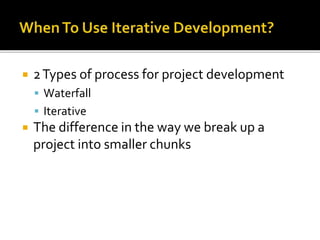
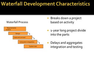
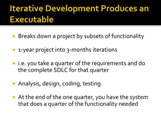
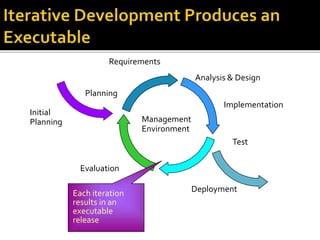
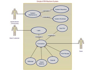
 Unified Modeling Language
 Family of graphical notations
 Backed by single meta-model
 Helps in describing and designing s/w system
 Particularly oo style
 Discussion abt design
 Open standard, controlled by OMG ( Object
ManagementGroup)
 1980s, Object Oriented languages used
widely
 Then the concept of Object oriented
graphical design languages established
 Grady Booch, Ivar Jcobson, Jim Rumbaugh
are the creators of UML
Web - June 1996
OOPSLA 95
Public
Feedback
OMG Acceptance, Nov 1997
Final submission to OMG, Sept 1997
First submission to OMG, Jan 1997
UML 1.0UML partners
UML 1.1
UML 1.4
UML 2.0
Planned minor revision (2000)
Planned major revision (2001)
UML 1.3Current minor revision 1999
 UML defines notations and meta-model
 Notation :
 Graphical stuff in models
 Graphical syntax of the modeling language
 Primarily meta-model is developed
 RUP is independent of UML
 Related concepts
 RUP is process framework
 It is essentially an iterative process
 Four phases of RUP projects
 Inception
 Elaboration
 Construction
 Transition
 Inception
 Initial evaluation of project
 You decide whether to commit enough funds to
do next phase or move forward.
 Elaboration
 Identifies primary use cases of the project in
iteration
 At the end, good sense of requirement and
skeletal working system
 Found and resolve the major risk
 Construction
 Actual building process
 Coding & testing
 Enough functionality for release
 Transition
 Late-stage activity
 Do not do iteratively
 Deployment of project
 Requirements analysis includes
 Users/customers want from system
 For that following UML techniques are used
 Use cases
▪ Describes how people interact with the system
 Class Diagram
▪ Drawn from conceptual perspective
 Activity Diagram
▪ Show the flow of the organization
▪ s/w and human activities interact
 State Diagram
▪ Life cycle of system
▪ with various states and events that change that state
 During Design Phase, Technical involvement of
system
 Precise notation is used
 Useful techniques for design phase
 Class Diagram
▪ s/w perspective
▪ Interrelation of the various classes
 Sequence Diagram
▪ Different kind of scenarios from system
 Package Diagram
▪ Large-scale organization of system
 State Diagram
 Deployment Diagram
▪ To show physical layout of the s/w
 2Types of process for project development
 Waterfall
 Iterative
 The difference in the way we break up a
project into smaller chunks
 Breaks down a project
based on activity
 1-year long project divide
into the parts
 Delays and aggregates
integration and testing
Code and unit test
Design
Subsystem integration
System test
Waterfall Process
Requirements
analysis
 Breaks down a project by subsets of functionality
 1-year project into 3-months iterations
 i.e. you take a quarter of the requirements and do
the complete SDLC for that quarter
 Analysis, design, coding, testing
 At the end of the one quarter, you have the system
that does a quarter of the functionality needed
Initial
Planning
Planning
Requirements
Analysis & Design
Implementation
Deployment
Test
Evaluation
Management
Environment
Each iteration
results in an
executable
release
• At the end of each iteration you have
production version of the s/w
• A project having multiple releases
• OO community in favor of ITERATIVE
DEVELOPMENT
• Used to capture the functional requirements
• Interactions between user and the system
• SCENARIO is the sequence of steps
describing an interaction
Uml Introduction and Use Cases

Uml Introduction and Use Cases

  • 2.
     Unified ModelingLanguage  Family of graphical notations  Backed by single meta-model  Helps in describing and designing s/w system  Particularly oo style  Discussion abt design  Open standard, controlled by OMG ( Object ManagementGroup)
  • 3.
     1980s, ObjectOriented languages used widely  Then the concept of Object oriented graphical design languages established  Grady Booch, Ivar Jcobson, Jim Rumbaugh are the creators of UML
  • 4.
    Web - June1996 OOPSLA 95 Public Feedback OMG Acceptance, Nov 1997 Final submission to OMG, Sept 1997 First submission to OMG, Jan 1997 UML 1.0UML partners UML 1.1 UML 1.4 UML 2.0 Planned minor revision (2000) Planned major revision (2001) UML 1.3Current minor revision 1999
  • 5.
     UML definesnotations and meta-model  Notation :  Graphical stuff in models  Graphical syntax of the modeling language  Primarily meta-model is developed
  • 7.
     RUP isindependent of UML  Related concepts  RUP is process framework  It is essentially an iterative process  Four phases of RUP projects  Inception  Elaboration  Construction  Transition
  • 8.
     Inception  Initialevaluation of project  You decide whether to commit enough funds to do next phase or move forward.  Elaboration  Identifies primary use cases of the project in iteration  At the end, good sense of requirement and skeletal working system  Found and resolve the major risk
  • 9.
     Construction  Actualbuilding process  Coding & testing  Enough functionality for release  Transition  Late-stage activity  Do not do iteratively  Deployment of project
  • 10.
     Requirements analysisincludes  Users/customers want from system  For that following UML techniques are used  Use cases ▪ Describes how people interact with the system  Class Diagram ▪ Drawn from conceptual perspective  Activity Diagram ▪ Show the flow of the organization ▪ s/w and human activities interact  State Diagram ▪ Life cycle of system ▪ with various states and events that change that state
  • 11.
     During DesignPhase, Technical involvement of system  Precise notation is used  Useful techniques for design phase  Class Diagram ▪ s/w perspective ▪ Interrelation of the various classes  Sequence Diagram ▪ Different kind of scenarios from system  Package Diagram ▪ Large-scale organization of system  State Diagram  Deployment Diagram ▪ To show physical layout of the s/w
  • 12.
     2Types ofprocess for project development  Waterfall  Iterative  The difference in the way we break up a project into smaller chunks
  • 13.
     Breaks downa project based on activity  1-year long project divide into the parts  Delays and aggregates integration and testing Code and unit test Design Subsystem integration System test Waterfall Process Requirements analysis
  • 14.
     Breaks downa project by subsets of functionality  1-year project into 3-months iterations  i.e. you take a quarter of the requirements and do the complete SDLC for that quarter  Analysis, design, coding, testing  At the end of the one quarter, you have the system that does a quarter of the functionality needed
  • 15.
  • 16.
    • At theend of each iteration you have production version of the s/w • A project having multiple releases • OO community in favor of ITERATIVE DEVELOPMENT
  • 17.
    • Used tocapture the functional requirements • Interactions between user and the system • SCENARIO is the sequence of steps describing an interaction

Editor's Notes

  • #14 Waterfall is conceptually straightforward because it produces a single deliverable. The fundamental problem of this approach is that it pushes risk forward in time, where it’s costly to undo mistakes from earlier phases. An initial design will likely be flawed with respect to its key requirements, and furthermore, the late discovery of design defects tends to result in costly overruns and/or project cancellation. The waterfall approach tends to mask the real risks to a project until it is too late to do anything meaningful about them.
  • #16 The earliest iterations address greatest risks. Each iteration produces an executable release. Each iteration includes integration and test. Resolves major risks before making large investments Enables early user feedback Makes testing and integration continuous Focuses project short-term objective milestones Makes possible deployment of partial implementations Iterative processes were developed in response to these waterfall characteristics. With an iterative process, the waterfall steps are applied iteratively. Instead of developing the whole system in lock step, an increment (that is, a subset of system functionality) is selected and developed, then another increment, etc. The selection of the first increment to be developed is based on risk, the highest priority risks first. To address the selected risk(s), choose a subset of use cases. Develop the minimal set of use cases that will allow objective verification (i.e., through a set of executable tests) of the risks that you have chosen. Then select the next increment to address the next highest risk, and so on. Thus you apply the waterfall within each iteration and the system evolves incrementally.