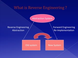
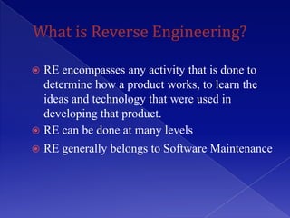
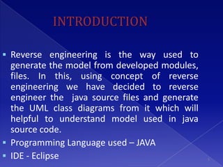
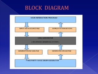
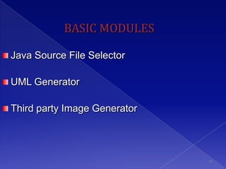
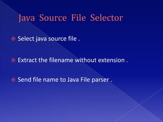
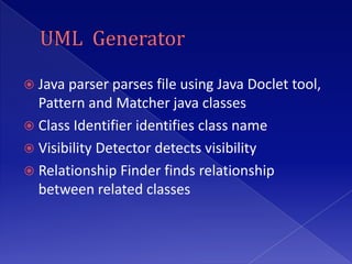
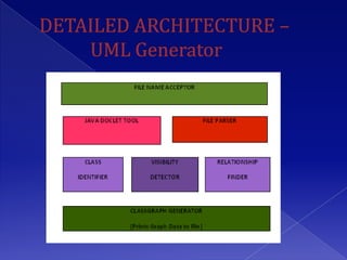
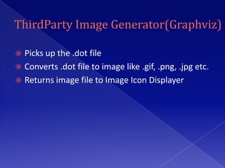
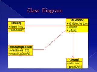
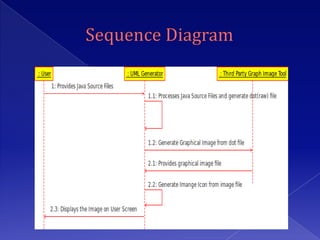
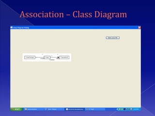
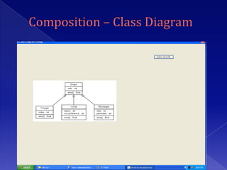
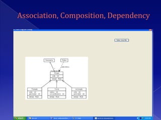
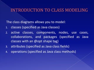
Project On


Under the guidance of:    Presented by:

Prof. Milind Gaikwad      Kundan Kumar       [Exam No- 828318]
                          Kumar Sourabh      [Exam No- 828297]
                          Ujjwal Kumar Singh [Exam No- 828289]

                                                          1
Abstraction System


Reverse Engineering                        Forward Engineering
    Abstraction                             Re-Implementation


               Old system           New System
 RE encompasses any activity that is done to
  determine how a product works, to learn the
  ideas and technology that were used in
  developing that product.
 RE can be done at many levels
   RE generally belongs to Software Maintenance
   INTRODUCTION
   OBJECTIVE
   SOFTWARE REQUIREMENTS
   HARDWARE REQUIREMENTS
   USER INTERFACE DESIGN
   ASSUMPTIONS
   BASIC MODULES
   CONSTRAINTS
   APPLICATION
   FEW RELATED SOFTWARE
   ADVANTAGES
   FUTURE SCOPE
   REFERENCES


                            4
INTRODUCTION

 Reverse engineering is the way used to
  generate the model from developed modules,
  files. In this, using concept of reverse
  engineering we have decided to reverse
  engineer the java source files and generate
  the UML class diagrams from it which will
  helpful to understand model used in java
  source code.
 Programming Language used – JAVA
 IDE - Eclipse                                 5
 Reverse engineer java source files into UML Class
  Diagrams.
 Class diagrams will include the displaying member
  data, member functions, visibility of member data
  and member functions along with relationships
  between two or many classes.
 The relationship includes composition, aggregation,
  association, generalization and dependency. It also
  displays the inheritance and implements
  relationships.
Software used :

1. Eclipse
   Core Java – Functionality
    Development
   Java Swing – UI Development

2. Graphviz
1. Pentium IV Processor or above
2.   256 MB RAM
3.   10 GB HDD
     Operating System :
1.   Window 98
2.   Window 2000
3.   Window XP
4.   UNIX / LINUX
 The class diagram shows the static structures of
  the system.
 A class is depicted on the class diagram as a
  rectangle with three horizontal sections
  The upper section shows the “class name” the
  middle section contains the “class attributes”
  and the lower section contains “class methods”.
 The UML class diagram can serve as the basic
  blueprint for developing software systems, and
  transform to Java classes easily.
 A class diagram can be used to display logical
  classes, which are typically the kinds of things
  the business people in an organization talk about
 Class diagrams can also be used to show
  implementation classes, which are the things
  that programmers typically deal with.
 The Doclet tools.jar should be added in the
  software.
 The graphviz image graph generation tool
  should be installed on computer else the
  image will not create.
 Eclipse should use the correct java version, it
  should not use old java version.
 The java source files should use tags
  mentioned.
BASIC MODULES

Java Source File Selector

UML Generator

Third party Image Generator


                              13
   Select java source file .


   Extract the filename without extension .

   Send file name to Java File parser .
 Java parser parses file using Java Doclet tool,
  Pattern and Matcher java classes
 Class Identifier identifies class name
 Visibility Detector detects visibility
 Relationship Finder finds relationship
  between related classes
 Picks up the .dot file
 Converts .dot file to image like .gif, .png, .jpg etc.
 Returns image file to Image Icon Displayer
The class diagrams allows you to model:
1. classes (specified as Java classes)
2. active classes, components, nodes, use cases,
   collaborations, and packages (specified as Java
   classes with an @opt shape tag)
3. attributes (specified as Java class fields)
4. operations (specified as Java class methods)
 tagged values (using
  the @tagvalue name value tag)
 implementation relationships (specified using
  the Java implements declaration)
 generalization relationships (specified using the
  Java “extends” declaration or (for
  multipleinheritance)the javadoc @extends tag)
 association relationships (specified using
  the javadoc @assoc tag)
 aggregation relationships (specified using
  the javadoc @has tag)
 composition relationships (specified using
  the javadoc @composed tag)
 dependency relationships (specified using
  the javadoc @depend tag)
1. Used to create design from java project in IT Firms,
   Educational Institutes.
2. By some modification can be used for C++ project in
   IT Firms, Educational institutes.
3. Used to reverse engineer any big product and after
   creating design again go for same product
   development and doing some enhancements. The
   product can be changed and can be created
   competitive to old products.
1. In future we can go for other UML Diagrams like
   sequence diagrams, collaboration diagrams.
2. Upgrade to create design of any java, C++ project.
REFERENCES
1.   www.google.com
2.   www.eclipse.org
3.   www.argouml.com
4.   www.ibm.com
5.   www.sun.com
6.   www.graphviz.org
7.   http://en.wikipedia.org/wiki/Class_diagram


                                                  31
THANK YOU

Ujjwalreverseengineeringppptfinal

  • 1.
    Project On Under theguidance of: Presented by: Prof. Milind Gaikwad Kundan Kumar [Exam No- 828318] Kumar Sourabh [Exam No- 828297] Ujjwal Kumar Singh [Exam No- 828289] 1
  • 2.
    Abstraction System Reverse Engineering Forward Engineering Abstraction Re-Implementation Old system New System
  • 3.
     RE encompassesany activity that is done to determine how a product works, to learn the ideas and technology that were used in developing that product.  RE can be done at many levels  RE generally belongs to Software Maintenance
  • 4.
    INTRODUCTION  OBJECTIVE  SOFTWARE REQUIREMENTS  HARDWARE REQUIREMENTS  USER INTERFACE DESIGN  ASSUMPTIONS  BASIC MODULES  CONSTRAINTS  APPLICATION  FEW RELATED SOFTWARE  ADVANTAGES  FUTURE SCOPE  REFERENCES 4
  • 5.
    INTRODUCTION  Reverse engineeringis the way used to generate the model from developed modules, files. In this, using concept of reverse engineering we have decided to reverse engineer the java source files and generate the UML class diagrams from it which will helpful to understand model used in java source code.  Programming Language used – JAVA  IDE - Eclipse 5
  • 6.
     Reverse engineerjava source files into UML Class Diagrams.  Class diagrams will include the displaying member data, member functions, visibility of member data and member functions along with relationships between two or many classes.  The relationship includes composition, aggregation, association, generalization and dependency. It also displays the inheritance and implements relationships.
  • 7.
    Software used : 1.Eclipse  Core Java – Functionality Development  Java Swing – UI Development 2. Graphviz
  • 8.
    1. Pentium IVProcessor or above 2. 256 MB RAM 3. 10 GB HDD Operating System : 1. Window 98 2. Window 2000 3. Window XP 4. UNIX / LINUX
  • 9.
     The classdiagram shows the static structures of the system.  A class is depicted on the class diagram as a rectangle with three horizontal sections The upper section shows the “class name” the middle section contains the “class attributes” and the lower section contains “class methods”.
  • 10.
     The UMLclass diagram can serve as the basic blueprint for developing software systems, and transform to Java classes easily.  A class diagram can be used to display logical classes, which are typically the kinds of things the business people in an organization talk about  Class diagrams can also be used to show implementation classes, which are the things that programmers typically deal with.
  • 11.
     The Doclettools.jar should be added in the software.  The graphviz image graph generation tool should be installed on computer else the image will not create.  Eclipse should use the correct java version, it should not use old java version.  The java source files should use tags mentioned.
  • 13.
    BASIC MODULES Java SourceFile Selector UML Generator Third party Image Generator 13
  • 14.
    Select java source file .  Extract the filename without extension .  Send file name to Java File parser .
  • 15.
     Java parserparses file using Java Doclet tool, Pattern and Matcher java classes  Class Identifier identifies class name  Visibility Detector detects visibility  Relationship Finder finds relationship between related classes
  • 17.
     Picks upthe .dot file  Converts .dot file to image like .gif, .png, .jpg etc.  Returns image file to Image Icon Displayer
  • 26.
    The class diagramsallows you to model: 1. classes (specified as Java classes) 2. active classes, components, nodes, use cases, collaborations, and packages (specified as Java classes with an @opt shape tag) 3. attributes (specified as Java class fields) 4. operations (specified as Java class methods)
  • 27.
     tagged values(using the @tagvalue name value tag)  implementation relationships (specified using the Java implements declaration)  generalization relationships (specified using the Java “extends” declaration or (for multipleinheritance)the javadoc @extends tag)
  • 28.
     association relationships(specified using the javadoc @assoc tag)  aggregation relationships (specified using the javadoc @has tag)  composition relationships (specified using the javadoc @composed tag)  dependency relationships (specified using the javadoc @depend tag)
  • 29.
    1. Used tocreate design from java project in IT Firms, Educational Institutes. 2. By some modification can be used for C++ project in IT Firms, Educational institutes. 3. Used to reverse engineer any big product and after creating design again go for same product development and doing some enhancements. The product can be changed and can be created competitive to old products.
  • 30.
    1. In futurewe can go for other UML Diagrams like sequence diagrams, collaboration diagrams. 2. Upgrade to create design of any java, C++ project.
  • 31.
    REFERENCES 1. www.google.com 2. www.eclipse.org 3. www.argouml.com 4. www.ibm.com 5. www.sun.com 6. www.graphviz.org 7. http://en.wikipedia.org/wiki/Class_diagram 31
  • 32.