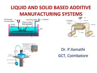
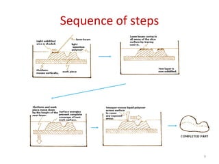
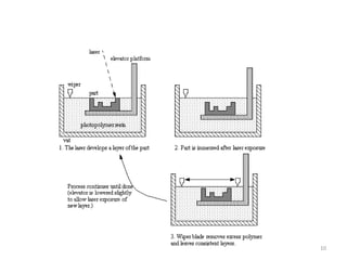
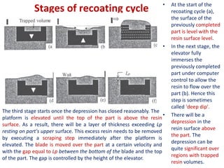
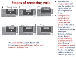
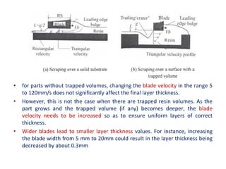
LIQUID AND SOLID BASED ADDITIVE
MANUFACTURING SYSTEMS
Dr. P.Ilamathi
GCT, Coimbatore
Cured
Resin
XY Scanning
UV Laser Beam
Photo-curable
Resin (Liquid)
Top of the Liquid Elevator
Vat
UNIT-III LIQUID BASED AND SOLID BASED ADDITIVE
MANUFACTURING SYSTEMS
• Stereo lithography Apparatus (SLA): Principle, pre-build process, part-
building and post-build processes, photo polymerization of SL resins,
part quality and process planning, recoating issues, materials,
advantages, limitations and applications. Solid Ground Curing (SGC):
working principle, process, strengths, weaknesses and applications.
Fused deposition Modeling (FDM): Principle, details of processes,
process variables, types, products, materials and application.
Laminated Object Manufacturing (LOM): Working Principles, details of
processes, products, materials, advantages, limitations and
applications.
2
StereoLithography (SLA) - Principle
• The SLA process is based
fundamentally on the following
principles:
• (1) Parts are built from a photo-
curable liquid resin that cures
when exposed to a laser beam
(basically, undergoing the
photopolymerization process)
which scans across the surface of
the resin.
• (2) The building is done layer by
layer, each layer being scanned
by the optical scanning system
and controlled by an elevation
mechanism which lowers at the
completion of each layer.
3
• Patented in 1986 by inventor, Charles
W. Hull
• 3D systems corporation, California
1. Pre-build Processes
• Solid or surface model of the part to be created in a suitable CAD
system.
• Solid model to be tessellated and presented as an .STL file.
• The number of layers, the geometry of the cross-section of each
layer as well as the overall part accuracy and surface finish depend
on the orientation of the part relative to the vertical. It is therefore
advisable to determine the optimal part orientation. (stair stepping
and build time.)
• Support Generation.
• After generating support structures, both the part and supports are
mathematically 'sliced' by the computer into a series of parallel
horizontal planes. During this step, the S L process planner will also
select the Layer thickness, the building style, the hatch spacing, the
cure depths, the line width compensation value, and the shrinkage
compensation values.
10/10/2022 4
1. Pre-build Processes
• Merging the part and the supports.
• Selection of operational parameters such as the number of
recoater blades per layer, the sweep period, and z-wait period.
• The final pre-build process involves ensuring that the level of the
liquid resin in the vat is at the proper z-level for optimum laser
focus.
10/10/2022 5
2. Part Building
Using SLA
6
The entire machine is a sealed
system (to prevent the fumes
from escaping) consisting of
several subsystems.
A liquid photopolymer resin is held in
a vat.
A laser device senses the level of the
resin.
StereoLithography (SLA)
7
Stereolithography: (1) at the start of the process, in which the initial layer is
added to the platform; and (2) after several layers have been added so that
the part geometry gradually takes form.
2. Part Building Using SLA
• The model is built upon a platform situated just below the surface
in a vat of liquid epoxy or acrylate resin.
• A low-power highly focused laser traces out the first layer,
solidifying the model’s cross section while leaving excess areas
liquid. (tracing process)
• Next, an elevator incrementally lowers the platform into the liquid
polymer.
• A sweeper re-coats the solidified layer with liquid, and the laser
traces the second layer atop the first. (recoating process)
• This process is repeated until the prototype is complete.
Afterwards, the solid part is removed from the vat and rinsed clean
of excess liquid.
• Uncured resin is removed , Supports are broken off and the model
is then placed in an ultraviolet oven for complete curing.
8
Sequence of steps
9
10
3. Post-build Processes
• Draining the part : The part is left to stand for sufficient time to
allow excess resin to drain back into the vat.
• Further, many parts contain cavities capable of trapping liquid
resin.
• Some of the trapped resin may be drained by manually tilting the
platform over its support arms.
• SL resins are fairly expensive. So, it is of importance to save the
excess resin by letting it flow back into the vat.
• Part Removal: the platform and the part are manually removed
from the machine using rubber gloves and placed in a shallow-
rimmed stainless steel tray or on to cellulose padding.
3. Post-build Processes
• Part Cleaning: The removed components are then wiped with a
paper towel. Narrow gaps may be wiped using 'Q-tips'.
• The components are then subjected to solvent cleaning in a special
apparatus. One method is to remove excess resin using TPM
(tripropylene glycol monomethyl ether).
• Next they are rinsed with water followed by rinsing with isopropyl
alcohol.
• Part Drying: The cleaned components are then dried using low-
pressure compressed air so that any residual resin and solvent
layers sticking to the part and platform are removed. The removal
needs to be thorough.
• Residual resin stuck in the narrow passages, comers, or blind holes
of the part can adversely affect part accuracy by getting
polymerized in the subsequent post-curing operation. In contrast,
the residual solvent layer cannot post cure. This can result in a
tacky surface.
3. Post-build Processes
• Post-curing: Part is removed very carefully from the platform using
a flat bladed knife, fine scissors, and/or a 'X-acto' knife. At this
stage, the part is in a green state, i.e., it is not fully cured.
• To reach a fully polymerized state, the green part is placed in a
post-curing apparatus (PCA).
• A PCA subjects the green part to broadband or continuum ultra-
violet radiation.
• Most parts can be post-cured within a couple of hours. Large parts
may require as much as 10 hours.
• Part Finishing: Because of the layered process, the model has a
surface composed of stair steps. Sanding can remove the stair steps
for a cosmetic finish.
• For aesthetic purposes, the model can be painted.
PHOTO-POLYMERIZATION OF SL RESINS
• SL Polymers: (Materials)
• Almost all SLA use a photo-curable liquid resin as the part material.
• The major photopolymers used in 3D Systems' SLA machines are
curable in the UV range (200-400nm).
• UV -curable photopolymers are resins formulated from photo
initiators and reactive liquid monomers. There is a large variety of
them.
• Some contain fillers and other chemicals to mechanical strength
requirements.
• The process through which photopolymers are cured is called
photo-polymerization.
• In the beginning, the resins were mainly acrylic-based, although
urethane acrylate, vinyl ether, and epoxy acrylate materials were
also developed. However, most of the newer resins are epoxies.
SL Polymers (Materials)
• Different resins are used to suit different SLA machines.
• Each type of resin has its own characteristics and mechanical
properties such as achievable accuracy, speed of photo-
polymerization, temperature resistance, humidity resistance, optical
clarity, and color.
• These may be obtained from the catalogs of the respective vendors.
• Standard resin - high stiffness, high-resolution prints with a smooth
injection molding-like finish
• Clear resin - optical transparency
• Tough resin (ABS-like) - withstand high stress and strain
• Durable resin (PP-like) - wear-resistant and flexible material
• Heat-resistant resin - high thermal stability
• Rubber-like resin (flexible) - low tensile modulus and high elongation
at break
• Ceramic-filled resin (Rigid) - very stiff and rigid parts, with a very
smooth surface finish.
Photo-polymerization
• Polymerization is the process of linking small molecules (known as
monomers) into chain-like larger molecules (known as polymers).
When the chain-like polymers are linked further to one another, a
cross-linked polymer is said to be formed.
• Photo polymerization is polymerization initiated by a photochemical
process whereby the starting point is usually the induction of energy
from the radiation source.
• A catalyst is required for polymerization to take place at a
reasonable rate. This catalyst is usually a free radical which may be
generated either thermally or photochemically.
• The source of a photochemically generated radical is a
photoinitiator, which reacts with an actinic photon to produce the
radicals that catalyze the polymerization process.
Photo-polymerization
• Types:
• Free-radical photopolymerization: Photoinitiator molecules, Pi, are
mixed with the monomers.
• Cationic photopolymerization : cationic initiators, usually iodinium
or sulfonium salts.
• Process:
• Photoinitiator molecules, Pi, which are mixed with the monomers,
M, are exposed to a UV source of actinic photons.
• The photoinitiators absorb some of the photons and are in an
excited state.
• Some of these are converted into reactive initiator molecules, P•,
after undergoing several complex chemical energy transformation
steps.
• These molecules then
react with a monomer
molecule to form a
polymerization
initiating molecule,
PM•. This is the chain
initiation step.
• Once activated,
additional monomer
molecules go on to
react in the chain
propagation step,
forming longer
molecules, PMMM•
until a chain inhibition
process terminates the
polymerization
reaction.
Photo-polymerization
• The longer the reaction is sustained, the higher will be the
molecular weight of the resulting polymer.
• If the monomer molecules have three or more reactive chemical
groups, the resulting polymer will be cross-linked, and this will
generate an insoluble continuous network of molecules.
• During polymerization, it is important that the polymers are
sufficiently cross-linked so that the polymerized molecules do not
redissolve back into the liquid monomers.
• The photopolymerized molecules must also possess sufficient
strength to remain structurally sound while the cured resin is
subjected to various forces during recoating.
• Commercially available cationic monomers include epoxies and
vinylethers.
• Cationic resins are attractive as prototype materials as they have
better physical and mechanical properties.
• However the process may require higher exposure time or a higher
power laser.
RECOATING ISSUES - Recoating Cycle
• Recoating is the process of establishing a new layer of fresh resin
over the previously cured layer.
• use a blade (knife-edge) and an elevator.
• A successful recoating step is one that is capable of establishing a
fresh layer of liquid resin of thickness exactly equal to the desired
thickness, Lp, within a reasonably short time. An incorrect layer
thickness will adversely affect the accuracy of the product.
• As a result, one needs to adopt quite a complex recoating cycle
involving several stages.
Stages of recoating cycle • At the start of the
recoating cycle (a),
the surface of the
previously completed
part is level with the
resin surface level.
• In the next stage, the
elevator fully
immerses the
previously completed
part under computer
control to allow the
resin to flow over the
part (b). Hence this
step is sometimes
called 'deep dip'.
• There will be a
depression in the
resin surface above
the part. The
depression can be
quite significant over
regions with trapped
resin volumes.
The third stage starts once the depression has closed reasonably. The
platform is elevated until the top of the part is above the resin
surface. As a result, there will be a layer of thickness exceeding Lp
resting on part's upper surface. This excess resin needs to be removed
by executing a scraping step immediately after the platform is
elevated. The blade is moved over the part at a certain velocity and
with the gap equal to Lp between the bottom of the blade and the top
of the part. The gap is controlled by the height of the elevator.
Stages of recoating cycle • The elevator is
lowered again such
that the part is in the
right position for
scanning the next
layer.
• Owing to finite
surface tension
effects, there is
usually a visible
crease at the solid to
liquid interface
around the perimeter
of the part.
Experiments have
shown that this
crease fades away
exponentially over
time. Hence, a
waiting period (called
'Z Wait') is introduced
for the resin surface
to blend and reach
the configuration (f)
The Z-wait period is usually determined
through a compromise between surface non-
uniformity and build time.
• for parts without trapped volumes, changing the blade velocity in the range 5
to 120mm/s does not significantly affect the final layer thickness.
• However, this is not the case when there are trapped resin volumes. As the
part grows and the trapped volume (if any) becomes deeper, the blade
velocity needs to be increased so as to ensure uniform layers of correct
thickness.
• Wider blades lead to smaller layer thickness values. For instance, increasing
the blade width from 5 mm to 20mm could result in the layer thickness being
decreased by about 0.3mm
Recoating Issues – Resin Level Control
• Most SL resins undergo volumetric shrinkages between 3% to 5% owing to
polymerization, so there will be a fall in liquid level after each layer has
been built. To overcome this problem, most S L machines incorporate a
level compensation module.
• Machines direct a helium-neon (He-Ne) laser beam on to the resin surface
so that the reflected beam is received by a silicon bi-cell detector or on
larger machines, by a silicon linear cell.
• Linear cells consist of a linear array of silicon cells. The difference in
voltage outputs from each end of the cell and where the light from the
diode hits the linear cell is used as the signal. This approach greatly
simplifies the level control software module.
• After a layer has been built, the level sensor checks the resin level. If the
level is outside a tolerance band, a computer-controlled stepper motor
activates a plunger that displaces the required amount of resin.
• A problem with this types of systems is that they are sensitive to
discontinuities in the resin surface. Such discontinuities usually arise from
small waves or bubbles created while the part is moving inside the vat.
The resulting spurious signals could get interpreted as genuine signals
providing information about the resin level. This could result in a 'hunting'
system.
• For overcoming, this problem, several SL machines started incorporating
an indium gallium aluminum phosphide (InGaAlP) visible diode lasers for
resin level detection. Such lasers have a much longer operational life than
He-Ne lasers. The diode laser leveling (DLL) systems have demonstrated a
leveling accuracy of about ±7.5 μm. This is quite acceptable since SL layer
thickness is usually in the range of 100 to 200 μm.
Recoating Issues – Resin Level Control
Advantages
• Round the clock operation: The SLA can be used continuously and
unattended round the clock.
• Good user support: The computerized process serves as a good
user support.
• Build volumes: The different SLA machines have build volumes
ranging from small to large to suit the needs of different users.
• Good accuracy: The SLA has good accuracy and can thus be used for
many application areas.
• Surface finish: The SLA can obtain one of the best surface finishes
amongst AM technologies.
• Wide range of materials: There is a wide range of materials, from
general-purpose materials to specialty materials for specific
applications.
Disadvantages
• Requires support structures: Structures that have overhangs and
undercuts must have supports that are designed and fabricated
together with the main structure.
• Requires post-processing: Post-processing includes removal of
supports and other unwanted materials, which is tedious, time
consuming and can damage the model.
• Requires post-curing: Post-curing may be needed to cure the object
completely and ensure the integrity of the structure.
Applications
The range of applications include:
(1) Models for conceptualization, packaging and presentation.
(2) Prototypes for design, analysis, verification and functional testing.
(3) Parts for prototype tooling and low volume production tooling.
(4) Patterns for investment casting, sand casting and molding.
(5) Tools for fixture and tooling design, and production tooling.
SOLID GROUND CURING (SGC)
• Solid Ground Curing (SGC) System is produced by Cubital Ltd., Israel
and commercial sales began in 1991.
• Like stereolithography, SGC works by curing a photosensitive
polymer layer by layer to create a solid model based on CAD
geometric data
• Instead of using a scanning laser beam to cure a given layer, the
entire layer is exposed to a UV source through a mask above the
liquid polymer
• Hardening takes 2 to 3 s for each layer
• Solid Ground Curing process includes three main steps:
• data preparation,
• mask generation and
• model making
Data Preparation
• CAD model of the job to be prototyped is prepared and the cross-
sections are generated digitally and transferred to the mask
generator.
• The software used, Cubital’s Solider DFE (Data Front End) software,
is a special-purpose CAD application package that processes solid
model CAD files prior to sending them to Cubital Solider system.
• DFE can search and correct flaws in the CAD files and render files
on-screen for visualization purposes.
• Solider DFE accepts CAD files in the STL format and other widely
used formats exported by most commercial CAD systems.
Mask Generation
• After data are received, the mask plate is charged through an
“imagewise” ionographic process. The charged image is then
developed with electrostatic toner.
Model
Making
Main components of SGC
(1) Data Front End (DFE) workstation.
(2) Model Production Machine (MPM). It includes:
(i) Process engine,
(ii) Operator’s console,
(iii) Vacuum generator.
(3) Automatic Dewaxing Machine (optional).
1. Mask preparation,
2. applying liquid
photopolymer layer,
3. mask positioning and
exposure of layer,
4. uncured polymer
removed from surface,
5. wax filling,
6. milling for flatness and
thickness
Solid Ground Curing
Facts about SGC
• Sequence for each layer takes about 90 seconds .
• The solid cubic form created in SGC consists of the solid
polymer and wax.
• The wax provides support for fragile and overhanging features
of the part during fabrication
– But can be melted away later to leave the free-standing
part.
Principle of SGC
• Parts are built, layer by layer, from a liquid photopolymer resin that
solidifies when exposed to UV light. irradiation source is a high
power collimated UV lamp and the image of the layer is generated
by masked illumination instead of optical scanning of a laser beam.
The mask is created from the CAD data input and “printed” on a
transparent substrate (the mask plate) by an nonimpact
ionographic printing process. The image is formed by depositing
black powder, a toner which adheres to the substrate
electrostatically. This is used to mask the uniform illumination of
the UV lamp. After exposure, the electrostatic toner is removed
from the substrate for reuse and the pattern for the next layer is
similarly “printed” on the substrate.
• Multiple parts may be processed and built in parallel by grouping
them into batches (runs) using Cubital’s proprietary software.
Principle of SGC
• Layers are created thicker than desired. This is to allow the layer to
be milled precisely to its exact thickness, thus giving overall control
of the vertical accuracy. This step also produces a roughened
surface of cured photopolymer, assisting adhesion of the next layer
to it. The next layer is then built immediately on the top of the
created layer.
• The process is self-supporting and does not require the addition of
external support structures to emerging parts since continuous
structural support for the parts is provided by the use of wax,
acting as a solid support material.
Advantages
(1) Parallel processing. The process is based on instant, simultaneous
curing of a whole cross-sectional layer area (rather than point-by
point curing). It has a high speed throughput that is about eight
times faster than its competitors. Its production costs can be 25%
to 50% lower. It is a time and cost saving process.
(2) Self-supporting. It is user-friendly, fast, and simple to use. It has a
solid modeling environment with unlimited geometry. The solid
wax supports the part in all dimensions and therefore a support
structure is not required.
(3) Fault tolerance. It has good fault tolerances. Removable trays allow
job changing during a run and layers are erasable.
(4) Unique part properties. The part that the Solider system produces is
reliable, accurate, sturdy, machinable, and can be mechanically
finished.
Advantages
(5) CAD to RP software. Cubital’s RP software, Data Front End (DFE),
processes solid model CAD files before they are transferred to the
Cubital’s machines. The DFE is an interactive and user friendly
software.
(6) Minimum shrinkage effect. This is due to the full curing of every
layer.
(7) High structural strength and stability. This is due to the curing
process that minimizes the development of internal stresses in the
structure. As a result, they are much less brittle.
(8) No hazardous odors are generated. The resin stays in a liquid state
for a very short time, and the uncured liquid is wiped off
immediately. Thus safety is considerably higher.
Disadvantages
(1) Requires large physical space. The size of the system is much larger
than other systems with a similar build volume size.
(2) Wax gets stuck in corners and crevices. It is difficult to remove wax
from parts with intricate geometry. Thus, some wax may be left
behind.
(3) Waste material produced. The milling process creates shavings,
which have to be cleaned from the machine.
(4) Noisy. The Solider system generates a high level of noise as
compared to other systems.
Applications
• The applications of Cubital’s system can be divided into four areas:
• (1) General applications. Conceptual design presentation, design
proofing, engineering testing, integration and fitting, functional
analysis, exhibitions and pre-production sales, market research, and
inter-professional communication.
• (2) Tooling and casting applications. Investment casting, sand
casting, and rapid, tool-free manufacturing of plastic parts.
• (3) Mold and tooling. Silicon rubber tooling, epoxy tooling, spray
metal tooling, acrylic tooling, and plaster mold casting.
• (4) Medical imaging. Diagnostic, surgical, operation and
reconstruction planning and custom prosthesis design.
43
Fused Deposition Modeling (FDM)
• Developed by Stratasys Inc.
• The model is built with Fused deposition of Plastic.
• Materials include ABS (standard and medical grade), elastomer (96
durometer), polycarbonate, polyphenolsulfone, and investment
casting wax.
• ABS plastic in the form of filament wound on spools.
• Like a baker decorating a cake, the controlled extrusion head
deposits very thin beads of material onto the build platform to
form the first layer.
• Parts up to 600 × 600 × 500 mm (24 × 24 × 20 inches) can be
produced.
10-Oct-22 RP ver 1.0 44
Schematic diagram of FDM
Part
Heated extrusion
head
Model & Support Filaments
Elevator & Platform
Schematic diagram of FDM
10-Oct-22 RP ver 1.0 45
10-Oct-22 46
Schematic diagram of FDM
FDM Process
• A geometric model of a conceptual design is created on a CAD software
which uses IGES or STL formatted files.
• It can then imported into the workstation where it is processed through
the QuickSlice® and SupportWorkTM propriety software before loading to
FDM 3000 or similar systems.
• For FDM Maxum and Titan, a newer software known as Insight is used.
The basic function of Insight is similar to that of QuickSlice® and the only
difference is that Insight does not need another software to auto-
generate the supports. The function is incorporated into the software
itself. Within this software, the CAD file is sliced into horizontal layers
after the part is oriented for the optimum build position, and any
necessary support structures are automatically detected and generated.
• The slice thickness can be set manually to anywhere between 0.172 to
0.356 mm (0.005 to 0.014 in) depending on the needs of the models.
• Tool paths of the build process are then generated which are downloaded
to the FDM machine.
48
• The filament on the spools is fed into an extrusion head and is heated to
0.50 C above its melting point 2800 C. (Semi liquid state)
• Filaments of heated thermoplastic are extruded from a tip that moves in
the x-y plane .
• Horizontal width of the extruded material can vary between 0.250 to
0.965 mm depending on model. This feature, called “road width”, can vary
from slice to slice.
• The platform is maintained at a lower temperature, so that the
thermoplastic quickly hardens (0.1 sec).
• After the platform lowers, the extrusion head deposits a second layer
upon the first.
• Supports are built along the way, fastened to the part either with a
second, weaker material or with a perforated junction.
• Two heads
– Build material
– Support Material
– At any time only one head is working
• Support material will be removed afterwards either manually breaking it
or dissolving it in water with ultrasonic.
FDM Principle
• The principle of the FDM is based on surface chemistry, thermal
energy, and layer manufacturing technology.
• Parameters which affect performance and functionalities of the
system are material column strength, material flexural modulus,
material viscosity, positioning accuracy, road widths, deposition
speed, volumetric flow rate, tip diameter, envelope temperature,
and part geometry.
Advantages
(1) Fabrication of functional parts. FDM process is able to fabricate
prototypes with materials that are similar to that of the actual molded
product. With ABS, it is able to fabricate fully functional parts that have
85% of the strength of the actual molded part. This is especially useful in
developing products that require quick prototypes for functional testing.
(2) Minimal wastage. The FDM process build parts directly by extruding semi-
liquid melt onto the model. Thus only those material needed to build the
part and its support are needed, and material wastages are kept to a
minimum. There is also little need for cleaning up the model after it has
been built.
(3) Ease of support removal. With the use of Break Away Support System
(BASS) and Water Works Soluble Support System, support structures
generated during the FDM building process can be easily broken off or
simply washed away. This makes it very convenient for users to get to
their prototypes very quickly and there is very little or no post-processing
necessary.
Advantages
(4) Ease of material change. Build materials, supplied in spool form (or
cartridge form in the case of the Dimension or Prodigy Plus), are easy to
handle and can be changed readily when the materials in the system are
running low. This keeps the operation of the machine simple and the
maintenance relatively easy.
Disadvantages
(1) Restricted accuracy. Parts built with the FDM process usually have
restricted accuracy due to the shape of the material used, i.e., the
filament form. Typically, the filament used has a diameter of 1.27 mm and
this tends to set a limit on how accurately the part can be built.
(2) Slow process. The building process is slow, as the whole cross sectional
area needs to be filled with building materials. Building speed is restricted
by the extrusion rate or the flow rate of the build material from the
extrusion head. As the build material used are plastics and their viscosities
are relatively high, the build process cannot be easily speeded up.
(3) Unpredictable shrinkage. As the FDM process extrudes the build material
from its extrusion head and cools them rapidly on deposition, stresses
induced by such rapid cooling invariably are introduced into the model. As
such, shrinkages and distortions caused to the model built are a common
occurrence and are usually difficult to predict, though with experience,
users may be able to compensate for these by adjusting the process
parameters of the machine.
Applications
(1) Models for conceptualization and presentation. Models can be
marked, sanded, painted and drilled and thus can be finished to be
almost like the actual product.
(2) Prototypes for design, analysis and functional testing. The system
can produce a fully functional prototype in ABS. The resulting ABS
parts have 85% of the strength of the actual molded part. Thus
actual testing can be carried out, especially with consumer
products.
(3) Patterns and masters for tooling. Models can be used as patterns
for investment casting, sand casting and molding.
10-Oct-22 54
Laminated Object Manufacturing
• Developed by Helisys, CA
• In this technique, layers of adhesive-coated sheet material are
bonded together to form a prototype.
• The original material consists of paper laminated with heat-
activated glue and rolled up on spools.
• Materials : plastic, water-repellent paper, and ceramic and metal
powder tapes. The most popular material has been Kraft paper
with a polyethylene-based heat seal adhesive system because it is
widely available, cost-effective, and environmental friendly.
10-Oct-22 RP ver 1.0 55
Schematic diagram of LOM
Principle
(1) Parts are built, layer-by-layer, by laminating each layer of paper or
other sheet-form materials and the contour of the part on that
layer is cut by a CO2 laser.
(2) Each layer of the building process contains the cross-sections of
one or many parts. The next layer is then laminated and built
directly on top of the laser-cut layer.
(3) The Z-control is activated by an elevation platform, which lowers
when each layer is completed, and the next layer is then laminated
and ready for cutting. The Z-height is then measured for the exact
height so that the corresponding cross sectional data can be
calculated for that layer.
(4) No additional support structures are necessary as the “excess”
material, which are cross-hatched for later removal, act as the
support.
10-Oct-22 57
Step-by-step procedure
• A feeder/collector mechanism advances the sheet over the build
platform, where a base has been constructed from paper and
double-sided foam tape.
• Next, a heated roller applies pressure to bond the paper to the
base. A focused laser cuts the outline of the first layer into the
paper and then cross-hatches the excess area (the negative space
in the prototype).
• Cross-hatching breaks up the extra material, making it easier to
remove during post-processing.
• During the build, the excess material provides excellent support for
overhangs and thin-walled sections.
• After the first layer is cut, the platform lowers out of the way and
fresh material is advanced.
10-Oct-22 58
Step-by-step procedure
• The platform rises to slightly below the previous height, the roller
bonds the second layer to the first, and the laser cuts the second
layer.
• This process is repeated as needed to build the part, which will
have a wood-like texture.
• Because the models are made of paper, they must be sealed and
finished with paint or varnish to prevent moisture damage.
10-Oct-22 59
Schematic diagram of LOM
Post
Processing
(a) The laminated stack is
removed from the
machine’s elevator plate.
(b) The surrounding wall is
lifted off the object to
expose cubes of excess
material.
(c) Cubes are easily
separated from the
object’s surface.
(d) The object’s surface can
then be sanded, polished
or painted, as desired.
SLA LOM
10-Oct-22 61
Advantages
(1) Wide variety of materials. In principle, any material in sheet form can be
used in the LOM systems. These include a wide variety of organic and
inorganic materials such as paper, plastics, metals, composites and
ceramics. Commercial availability of these materials allow users to vary
the type and thickness of manufacturing materials to meet their
functional requirements and specific applications of the prototype.
(2) Fast build time. The laser in the LOM process does not scan the entire
surface area of each cross-section, rather it only outlines its periphery.
Therefore, parts with thick sections are produced just as quickly as those
with thin sections, making the LOM process especially advantageous for
the production of large and bulky parts.
(3) High precision. The feature to feature accuracy that can be achieved with
LOM machines is usually better than 0.127 mm (0.005"). The LOM system
uses a precise X–Y positioning table to guide the laser beam; it is
monitored throughout the build process by the closed-loop, real-time
motion control system, resulting in an accuracy of ±0.127 mm regardless
of the part size. The Z-axis is also controlled using a real-time, closed-loop
feedback system.
Advantages
(4) Support structure. There is no need for additional support structure as the
part is supported by its own material that is outside the periphery of the
part built. These are not removed during the LOM process and therefore
automatically act as supports for its delicate or overhang features.
(5) Post-curing. The LOM process does not need to convert expensive, and in
some cases toxic, liquid polymers to solid plastics or plastic powders into
sintered objects. Because sheet materials are not subjected to either
physical or chemical phase changes, the finished LOM parts do not
experience warpage, internal residual stress, or other deformations.
Disadvantages
(1) Precise power adjustment. The power of the laser used for cutting
the perimeter (and the crosshatches) of the prototype needs to be
precisely controlled so that the laser cuts only the current layer of
lamination and not penetrate into the previously cut layers. Poor
control of the cutting laser beam may cause distortion to the entire
prototype.
(2) Fabrication of thin walls. The LOM process is not well suited for
building parts with delicate thin walls, especially in the Z-direction.
This is because such walls usually are not sufficiently rigid to
withstand the post-processing process when the cross-hatched
outer perimeter portion of the block is being removed. The person
performing the post-processing task of separating the thin wall of
the part from its support must be fully aware of where such
delicate parts are located in the model and take sufficient
precautions so as not to damage these parts.
Disadvantages
(3) Integrity of prototypes. The part built by the LOM process is
essentially held together by the heat sealed adhesives. The integrity
of the part is therefore entirely dependent on the adhesive
strength of the glue used, and as such is limited to this strength.
Therefore, parts built may not be able to withstand the vigorous
mechanical loading that the functional prototypes may require.
(4) Removal of supports. The most labor-intensive part of the LOM
process is its last phase of post-processing when the part has to be
separated from its support material within the rectangular block of
laminated material. This is usually done with wood carving tools
and can be tedious and time consuming. The person working during
this phase needs to be careful and aware of the presence of any
delicate parts within the model so as not to damage it.
Applications
(1) Visualization. Many companies utilize LOM’s ability to produce
exact dimensions of a potential product purely for visualization.
LOM part’s wood-like composition allows it to be painted or
finished as a true replica of the product. As the LOM procedure is
inexpensive several models can be created, giving sales and
marketing executives opportunities to utilize these prototypes for
consumer testing, marketing product introductions, packaging
samples, and samples for vendor quotations.
(2) Form, fit and function. LOM parts lend themselves well for design
verification and performance evaluation. In low-stress
environments LOM parts can withstand basic tests, giving
manufacturers the opportunity to make changes as well as evaluate
the aesthetic property of the prototype in its total environment.
Applications
(3) Manufacturing. The LOM part’s composition is such that, based on
the sealant or finishing products used, it can be further tooled for
use as a pattern or mold for most secondary tooling techniques
including: investment casting, casting, sanding casting, injection
molding, silicon rubber mold, vacuum forming and spray metal
molding.
(4) Rapid tooling. Two part negative tooling is easily created with LOM
systems. Since the material is solid and inexpensive, bulk
complicated tools are cost effective to produce. These wood-like
molds can be used for injection of wax, polyurethane, epoxy or
other low pressure and low temperature materials. Also, the
tooling can be converted to aluminum or steel via the investment
casting process for use in high temperature molding processes.
U III LIQUID AND SOLID BASED ADDITIVE MANUFACTURING SYSTEMS.pdf

U III LIQUID AND SOLID BASED ADDITIVE MANUFACTURING SYSTEMS.pdf

  • 1.
    LIQUID AND SOLIDBASED ADDITIVE MANUFACTURING SYSTEMS Dr. P.Ilamathi GCT, Coimbatore Cured Resin XY Scanning UV Laser Beam Photo-curable Resin (Liquid) Top of the Liquid Elevator Vat
  • 2.
    UNIT-III LIQUID BASEDAND SOLID BASED ADDITIVE MANUFACTURING SYSTEMS • Stereo lithography Apparatus (SLA): Principle, pre-build process, part- building and post-build processes, photo polymerization of SL resins, part quality and process planning, recoating issues, materials, advantages, limitations and applications. Solid Ground Curing (SGC): working principle, process, strengths, weaknesses and applications. Fused deposition Modeling (FDM): Principle, details of processes, process variables, types, products, materials and application. Laminated Object Manufacturing (LOM): Working Principles, details of processes, products, materials, advantages, limitations and applications. 2
  • 3.
    StereoLithography (SLA) -Principle • The SLA process is based fundamentally on the following principles: • (1) Parts are built from a photo- curable liquid resin that cures when exposed to a laser beam (basically, undergoing the photopolymerization process) which scans across the surface of the resin. • (2) The building is done layer by layer, each layer being scanned by the optical scanning system and controlled by an elevation mechanism which lowers at the completion of each layer. 3 • Patented in 1986 by inventor, Charles W. Hull • 3D systems corporation, California
  • 4.
    1. Pre-build Processes •Solid or surface model of the part to be created in a suitable CAD system. • Solid model to be tessellated and presented as an .STL file. • The number of layers, the geometry of the cross-section of each layer as well as the overall part accuracy and surface finish depend on the orientation of the part relative to the vertical. It is therefore advisable to determine the optimal part orientation. (stair stepping and build time.) • Support Generation. • After generating support structures, both the part and supports are mathematically 'sliced' by the computer into a series of parallel horizontal planes. During this step, the S L process planner will also select the Layer thickness, the building style, the hatch spacing, the cure depths, the line width compensation value, and the shrinkage compensation values. 10/10/2022 4
  • 5.
    1. Pre-build Processes •Merging the part and the supports. • Selection of operational parameters such as the number of recoater blades per layer, the sweep period, and z-wait period. • The final pre-build process involves ensuring that the level of the liquid resin in the vat is at the proper z-level for optimum laser focus. 10/10/2022 5
  • 6.
    2. Part Building UsingSLA 6 The entire machine is a sealed system (to prevent the fumes from escaping) consisting of several subsystems. A liquid photopolymer resin is held in a vat. A laser device senses the level of the resin.
  • 7.
    StereoLithography (SLA) 7 Stereolithography: (1)at the start of the process, in which the initial layer is added to the platform; and (2) after several layers have been added so that the part geometry gradually takes form.
  • 8.
    2. Part BuildingUsing SLA • The model is built upon a platform situated just below the surface in a vat of liquid epoxy or acrylate resin. • A low-power highly focused laser traces out the first layer, solidifying the model’s cross section while leaving excess areas liquid. (tracing process) • Next, an elevator incrementally lowers the platform into the liquid polymer. • A sweeper re-coats the solidified layer with liquid, and the laser traces the second layer atop the first. (recoating process) • This process is repeated until the prototype is complete. Afterwards, the solid part is removed from the vat and rinsed clean of excess liquid. • Uncured resin is removed , Supports are broken off and the model is then placed in an ultraviolet oven for complete curing. 8
  • 9.
  • 10.
  • 11.
    3. Post-build Processes •Draining the part : The part is left to stand for sufficient time to allow excess resin to drain back into the vat. • Further, many parts contain cavities capable of trapping liquid resin. • Some of the trapped resin may be drained by manually tilting the platform over its support arms. • SL resins are fairly expensive. So, it is of importance to save the excess resin by letting it flow back into the vat. • Part Removal: the platform and the part are manually removed from the machine using rubber gloves and placed in a shallow- rimmed stainless steel tray or on to cellulose padding.
  • 12.
    3. Post-build Processes •Part Cleaning: The removed components are then wiped with a paper towel. Narrow gaps may be wiped using 'Q-tips'. • The components are then subjected to solvent cleaning in a special apparatus. One method is to remove excess resin using TPM (tripropylene glycol monomethyl ether). • Next they are rinsed with water followed by rinsing with isopropyl alcohol. • Part Drying: The cleaned components are then dried using low- pressure compressed air so that any residual resin and solvent layers sticking to the part and platform are removed. The removal needs to be thorough. • Residual resin stuck in the narrow passages, comers, or blind holes of the part can adversely affect part accuracy by getting polymerized in the subsequent post-curing operation. In contrast, the residual solvent layer cannot post cure. This can result in a tacky surface.
  • 13.
    3. Post-build Processes •Post-curing: Part is removed very carefully from the platform using a flat bladed knife, fine scissors, and/or a 'X-acto' knife. At this stage, the part is in a green state, i.e., it is not fully cured. • To reach a fully polymerized state, the green part is placed in a post-curing apparatus (PCA). • A PCA subjects the green part to broadband or continuum ultra- violet radiation. • Most parts can be post-cured within a couple of hours. Large parts may require as much as 10 hours. • Part Finishing: Because of the layered process, the model has a surface composed of stair steps. Sanding can remove the stair steps for a cosmetic finish. • For aesthetic purposes, the model can be painted.
  • 14.
    PHOTO-POLYMERIZATION OF SLRESINS • SL Polymers: (Materials) • Almost all SLA use a photo-curable liquid resin as the part material. • The major photopolymers used in 3D Systems' SLA machines are curable in the UV range (200-400nm). • UV -curable photopolymers are resins formulated from photo initiators and reactive liquid monomers. There is a large variety of them. • Some contain fillers and other chemicals to mechanical strength requirements. • The process through which photopolymers are cured is called photo-polymerization. • In the beginning, the resins were mainly acrylic-based, although urethane acrylate, vinyl ether, and epoxy acrylate materials were also developed. However, most of the newer resins are epoxies.
  • 15.
    SL Polymers (Materials) •Different resins are used to suit different SLA machines. • Each type of resin has its own characteristics and mechanical properties such as achievable accuracy, speed of photo- polymerization, temperature resistance, humidity resistance, optical clarity, and color. • These may be obtained from the catalogs of the respective vendors. • Standard resin - high stiffness, high-resolution prints with a smooth injection molding-like finish • Clear resin - optical transparency • Tough resin (ABS-like) - withstand high stress and strain • Durable resin (PP-like) - wear-resistant and flexible material • Heat-resistant resin - high thermal stability • Rubber-like resin (flexible) - low tensile modulus and high elongation at break • Ceramic-filled resin (Rigid) - very stiff and rigid parts, with a very smooth surface finish.
  • 16.
    Photo-polymerization • Polymerization isthe process of linking small molecules (known as monomers) into chain-like larger molecules (known as polymers). When the chain-like polymers are linked further to one another, a cross-linked polymer is said to be formed. • Photo polymerization is polymerization initiated by a photochemical process whereby the starting point is usually the induction of energy from the radiation source. • A catalyst is required for polymerization to take place at a reasonable rate. This catalyst is usually a free radical which may be generated either thermally or photochemically. • The source of a photochemically generated radical is a photoinitiator, which reacts with an actinic photon to produce the radicals that catalyze the polymerization process.
  • 17.
    Photo-polymerization • Types: • Free-radicalphotopolymerization: Photoinitiator molecules, Pi, are mixed with the monomers. • Cationic photopolymerization : cationic initiators, usually iodinium or sulfonium salts. • Process: • Photoinitiator molecules, Pi, which are mixed with the monomers, M, are exposed to a UV source of actinic photons. • The photoinitiators absorb some of the photons and are in an excited state. • Some of these are converted into reactive initiator molecules, P•, after undergoing several complex chemical energy transformation steps.
  • 18.
    • These moleculesthen react with a monomer molecule to form a polymerization initiating molecule, PM•. This is the chain initiation step. • Once activated, additional monomer molecules go on to react in the chain propagation step, forming longer molecules, PMMM• until a chain inhibition process terminates the polymerization reaction.
  • 19.
    Photo-polymerization • The longerthe reaction is sustained, the higher will be the molecular weight of the resulting polymer. • If the monomer molecules have three or more reactive chemical groups, the resulting polymer will be cross-linked, and this will generate an insoluble continuous network of molecules. • During polymerization, it is important that the polymers are sufficiently cross-linked so that the polymerized molecules do not redissolve back into the liquid monomers. • The photopolymerized molecules must also possess sufficient strength to remain structurally sound while the cured resin is subjected to various forces during recoating. • Commercially available cationic monomers include epoxies and vinylethers. • Cationic resins are attractive as prototype materials as they have better physical and mechanical properties. • However the process may require higher exposure time or a higher power laser.
  • 20.
    RECOATING ISSUES -Recoating Cycle • Recoating is the process of establishing a new layer of fresh resin over the previously cured layer. • use a blade (knife-edge) and an elevator. • A successful recoating step is one that is capable of establishing a fresh layer of liquid resin of thickness exactly equal to the desired thickness, Lp, within a reasonably short time. An incorrect layer thickness will adversely affect the accuracy of the product. • As a result, one needs to adopt quite a complex recoating cycle involving several stages.
  • 21.
    Stages of recoatingcycle • At the start of the recoating cycle (a), the surface of the previously completed part is level with the resin surface level. • In the next stage, the elevator fully immerses the previously completed part under computer control to allow the resin to flow over the part (b). Hence this step is sometimes called 'deep dip'. • There will be a depression in the resin surface above the part. The depression can be quite significant over regions with trapped resin volumes. The third stage starts once the depression has closed reasonably. The platform is elevated until the top of the part is above the resin surface. As a result, there will be a layer of thickness exceeding Lp resting on part's upper surface. This excess resin needs to be removed by executing a scraping step immediately after the platform is elevated. The blade is moved over the part at a certain velocity and with the gap equal to Lp between the bottom of the blade and the top of the part. The gap is controlled by the height of the elevator.
  • 22.
    Stages of recoatingcycle • The elevator is lowered again such that the part is in the right position for scanning the next layer. • Owing to finite surface tension effects, there is usually a visible crease at the solid to liquid interface around the perimeter of the part. Experiments have shown that this crease fades away exponentially over time. Hence, a waiting period (called 'Z Wait') is introduced for the resin surface to blend and reach the configuration (f) The Z-wait period is usually determined through a compromise between surface non- uniformity and build time.
  • 23.
    • for partswithout trapped volumes, changing the blade velocity in the range 5 to 120mm/s does not significantly affect the final layer thickness. • However, this is not the case when there are trapped resin volumes. As the part grows and the trapped volume (if any) becomes deeper, the blade velocity needs to be increased so as to ensure uniform layers of correct thickness. • Wider blades lead to smaller layer thickness values. For instance, increasing the blade width from 5 mm to 20mm could result in the layer thickness being decreased by about 0.3mm
  • 24.
    Recoating Issues –Resin Level Control • Most SL resins undergo volumetric shrinkages between 3% to 5% owing to polymerization, so there will be a fall in liquid level after each layer has been built. To overcome this problem, most S L machines incorporate a level compensation module. • Machines direct a helium-neon (He-Ne) laser beam on to the resin surface so that the reflected beam is received by a silicon bi-cell detector or on larger machines, by a silicon linear cell. • Linear cells consist of a linear array of silicon cells. The difference in voltage outputs from each end of the cell and where the light from the diode hits the linear cell is used as the signal. This approach greatly simplifies the level control software module. • After a layer has been built, the level sensor checks the resin level. If the level is outside a tolerance band, a computer-controlled stepper motor activates a plunger that displaces the required amount of resin.
  • 25.
    • A problemwith this types of systems is that they are sensitive to discontinuities in the resin surface. Such discontinuities usually arise from small waves or bubbles created while the part is moving inside the vat. The resulting spurious signals could get interpreted as genuine signals providing information about the resin level. This could result in a 'hunting' system. • For overcoming, this problem, several SL machines started incorporating an indium gallium aluminum phosphide (InGaAlP) visible diode lasers for resin level detection. Such lasers have a much longer operational life than He-Ne lasers. The diode laser leveling (DLL) systems have demonstrated a leveling accuracy of about ±7.5 μm. This is quite acceptable since SL layer thickness is usually in the range of 100 to 200 μm. Recoating Issues – Resin Level Control
  • 26.
    Advantages • Round theclock operation: The SLA can be used continuously and unattended round the clock. • Good user support: The computerized process serves as a good user support. • Build volumes: The different SLA machines have build volumes ranging from small to large to suit the needs of different users. • Good accuracy: The SLA has good accuracy and can thus be used for many application areas. • Surface finish: The SLA can obtain one of the best surface finishes amongst AM technologies. • Wide range of materials: There is a wide range of materials, from general-purpose materials to specialty materials for specific applications.
  • 27.
    Disadvantages • Requires supportstructures: Structures that have overhangs and undercuts must have supports that are designed and fabricated together with the main structure. • Requires post-processing: Post-processing includes removal of supports and other unwanted materials, which is tedious, time consuming and can damage the model. • Requires post-curing: Post-curing may be needed to cure the object completely and ensure the integrity of the structure.
  • 28.
    Applications The range ofapplications include: (1) Models for conceptualization, packaging and presentation. (2) Prototypes for design, analysis, verification and functional testing. (3) Parts for prototype tooling and low volume production tooling. (4) Patterns for investment casting, sand casting and molding. (5) Tools for fixture and tooling design, and production tooling.
  • 29.
  • 30.
    SOLID GROUND CURING(SGC) • Solid Ground Curing (SGC) System is produced by Cubital Ltd., Israel and commercial sales began in 1991. • Like stereolithography, SGC works by curing a photosensitive polymer layer by layer to create a solid model based on CAD geometric data • Instead of using a scanning laser beam to cure a given layer, the entire layer is exposed to a UV source through a mask above the liquid polymer • Hardening takes 2 to 3 s for each layer • Solid Ground Curing process includes three main steps: • data preparation, • mask generation and • model making
  • 31.
    Data Preparation • CADmodel of the job to be prototyped is prepared and the cross- sections are generated digitally and transferred to the mask generator. • The software used, Cubital’s Solider DFE (Data Front End) software, is a special-purpose CAD application package that processes solid model CAD files prior to sending them to Cubital Solider system. • DFE can search and correct flaws in the CAD files and render files on-screen for visualization purposes. • Solider DFE accepts CAD files in the STL format and other widely used formats exported by most commercial CAD systems.
  • 32.
    Mask Generation • Afterdata are received, the mask plate is charged through an “imagewise” ionographic process. The charged image is then developed with electrostatic toner.
  • 33.
  • 34.
    Main components ofSGC (1) Data Front End (DFE) workstation. (2) Model Production Machine (MPM). It includes: (i) Process engine, (ii) Operator’s console, (iii) Vacuum generator. (3) Automatic Dewaxing Machine (optional).
  • 35.
    1. Mask preparation, 2.applying liquid photopolymer layer, 3. mask positioning and exposure of layer, 4. uncured polymer removed from surface, 5. wax filling, 6. milling for flatness and thickness Solid Ground Curing
  • 36.
    Facts about SGC •Sequence for each layer takes about 90 seconds . • The solid cubic form created in SGC consists of the solid polymer and wax. • The wax provides support for fragile and overhanging features of the part during fabrication – But can be melted away later to leave the free-standing part.
  • 37.
    Principle of SGC •Parts are built, layer by layer, from a liquid photopolymer resin that solidifies when exposed to UV light. irradiation source is a high power collimated UV lamp and the image of the layer is generated by masked illumination instead of optical scanning of a laser beam. The mask is created from the CAD data input and “printed” on a transparent substrate (the mask plate) by an nonimpact ionographic printing process. The image is formed by depositing black powder, a toner which adheres to the substrate electrostatically. This is used to mask the uniform illumination of the UV lamp. After exposure, the electrostatic toner is removed from the substrate for reuse and the pattern for the next layer is similarly “printed” on the substrate. • Multiple parts may be processed and built in parallel by grouping them into batches (runs) using Cubital’s proprietary software.
  • 38.
    Principle of SGC •Layers are created thicker than desired. This is to allow the layer to be milled precisely to its exact thickness, thus giving overall control of the vertical accuracy. This step also produces a roughened surface of cured photopolymer, assisting adhesion of the next layer to it. The next layer is then built immediately on the top of the created layer. • The process is self-supporting and does not require the addition of external support structures to emerging parts since continuous structural support for the parts is provided by the use of wax, acting as a solid support material.
  • 39.
    Advantages (1) Parallel processing.The process is based on instant, simultaneous curing of a whole cross-sectional layer area (rather than point-by point curing). It has a high speed throughput that is about eight times faster than its competitors. Its production costs can be 25% to 50% lower. It is a time and cost saving process. (2) Self-supporting. It is user-friendly, fast, and simple to use. It has a solid modeling environment with unlimited geometry. The solid wax supports the part in all dimensions and therefore a support structure is not required. (3) Fault tolerance. It has good fault tolerances. Removable trays allow job changing during a run and layers are erasable. (4) Unique part properties. The part that the Solider system produces is reliable, accurate, sturdy, machinable, and can be mechanically finished.
  • 40.
    Advantages (5) CAD toRP software. Cubital’s RP software, Data Front End (DFE), processes solid model CAD files before they are transferred to the Cubital’s machines. The DFE is an interactive and user friendly software. (6) Minimum shrinkage effect. This is due to the full curing of every layer. (7) High structural strength and stability. This is due to the curing process that minimizes the development of internal stresses in the structure. As a result, they are much less brittle. (8) No hazardous odors are generated. The resin stays in a liquid state for a very short time, and the uncured liquid is wiped off immediately. Thus safety is considerably higher.
  • 41.
    Disadvantages (1) Requires largephysical space. The size of the system is much larger than other systems with a similar build volume size. (2) Wax gets stuck in corners and crevices. It is difficult to remove wax from parts with intricate geometry. Thus, some wax may be left behind. (3) Waste material produced. The milling process creates shavings, which have to be cleaned from the machine. (4) Noisy. The Solider system generates a high level of noise as compared to other systems.
  • 42.
    Applications • The applicationsof Cubital’s system can be divided into four areas: • (1) General applications. Conceptual design presentation, design proofing, engineering testing, integration and fitting, functional analysis, exhibitions and pre-production sales, market research, and inter-professional communication. • (2) Tooling and casting applications. Investment casting, sand casting, and rapid, tool-free manufacturing of plastic parts. • (3) Mold and tooling. Silicon rubber tooling, epoxy tooling, spray metal tooling, acrylic tooling, and plaster mold casting. • (4) Medical imaging. Diagnostic, surgical, operation and reconstruction planning and custom prosthesis design.
  • 43.
    43 Fused Deposition Modeling(FDM) • Developed by Stratasys Inc. • The model is built with Fused deposition of Plastic. • Materials include ABS (standard and medical grade), elastomer (96 durometer), polycarbonate, polyphenolsulfone, and investment casting wax. • ABS plastic in the form of filament wound on spools. • Like a baker decorating a cake, the controlled extrusion head deposits very thin beads of material onto the build platform to form the first layer. • Parts up to 600 × 600 × 500 mm (24 × 24 × 20 inches) can be produced.
  • 44.
    10-Oct-22 RP ver1.0 44 Schematic diagram of FDM Part Heated extrusion head Model & Support Filaments Elevator & Platform
  • 45.
    Schematic diagram ofFDM 10-Oct-22 RP ver 1.0 45
  • 46.
  • 47.
    FDM Process • Ageometric model of a conceptual design is created on a CAD software which uses IGES or STL formatted files. • It can then imported into the workstation where it is processed through the QuickSlice® and SupportWorkTM propriety software before loading to FDM 3000 or similar systems. • For FDM Maxum and Titan, a newer software known as Insight is used. The basic function of Insight is similar to that of QuickSlice® and the only difference is that Insight does not need another software to auto- generate the supports. The function is incorporated into the software itself. Within this software, the CAD file is sliced into horizontal layers after the part is oriented for the optimum build position, and any necessary support structures are automatically detected and generated. • The slice thickness can be set manually to anywhere between 0.172 to 0.356 mm (0.005 to 0.014 in) depending on the needs of the models. • Tool paths of the build process are then generated which are downloaded to the FDM machine.
  • 48.
    48 • The filamenton the spools is fed into an extrusion head and is heated to 0.50 C above its melting point 2800 C. (Semi liquid state) • Filaments of heated thermoplastic are extruded from a tip that moves in the x-y plane . • Horizontal width of the extruded material can vary between 0.250 to 0.965 mm depending on model. This feature, called “road width”, can vary from slice to slice. • The platform is maintained at a lower temperature, so that the thermoplastic quickly hardens (0.1 sec). • After the platform lowers, the extrusion head deposits a second layer upon the first. • Supports are built along the way, fastened to the part either with a second, weaker material or with a perforated junction. • Two heads – Build material – Support Material – At any time only one head is working • Support material will be removed afterwards either manually breaking it or dissolving it in water with ultrasonic.
  • 49.
    FDM Principle • Theprinciple of the FDM is based on surface chemistry, thermal energy, and layer manufacturing technology. • Parameters which affect performance and functionalities of the system are material column strength, material flexural modulus, material viscosity, positioning accuracy, road widths, deposition speed, volumetric flow rate, tip diameter, envelope temperature, and part geometry.
  • 50.
    Advantages (1) Fabrication offunctional parts. FDM process is able to fabricate prototypes with materials that are similar to that of the actual molded product. With ABS, it is able to fabricate fully functional parts that have 85% of the strength of the actual molded part. This is especially useful in developing products that require quick prototypes for functional testing. (2) Minimal wastage. The FDM process build parts directly by extruding semi- liquid melt onto the model. Thus only those material needed to build the part and its support are needed, and material wastages are kept to a minimum. There is also little need for cleaning up the model after it has been built. (3) Ease of support removal. With the use of Break Away Support System (BASS) and Water Works Soluble Support System, support structures generated during the FDM building process can be easily broken off or simply washed away. This makes it very convenient for users to get to their prototypes very quickly and there is very little or no post-processing necessary.
  • 51.
    Advantages (4) Ease ofmaterial change. Build materials, supplied in spool form (or cartridge form in the case of the Dimension or Prodigy Plus), are easy to handle and can be changed readily when the materials in the system are running low. This keeps the operation of the machine simple and the maintenance relatively easy.
  • 52.
    Disadvantages (1) Restricted accuracy.Parts built with the FDM process usually have restricted accuracy due to the shape of the material used, i.e., the filament form. Typically, the filament used has a diameter of 1.27 mm and this tends to set a limit on how accurately the part can be built. (2) Slow process. The building process is slow, as the whole cross sectional area needs to be filled with building materials. Building speed is restricted by the extrusion rate or the flow rate of the build material from the extrusion head. As the build material used are plastics and their viscosities are relatively high, the build process cannot be easily speeded up. (3) Unpredictable shrinkage. As the FDM process extrudes the build material from its extrusion head and cools them rapidly on deposition, stresses induced by such rapid cooling invariably are introduced into the model. As such, shrinkages and distortions caused to the model built are a common occurrence and are usually difficult to predict, though with experience, users may be able to compensate for these by adjusting the process parameters of the machine.
  • 53.
    Applications (1) Models forconceptualization and presentation. Models can be marked, sanded, painted and drilled and thus can be finished to be almost like the actual product. (2) Prototypes for design, analysis and functional testing. The system can produce a fully functional prototype in ABS. The resulting ABS parts have 85% of the strength of the actual molded part. Thus actual testing can be carried out, especially with consumer products. (3) Patterns and masters for tooling. Models can be used as patterns for investment casting, sand casting and molding.
  • 54.
    10-Oct-22 54 Laminated ObjectManufacturing • Developed by Helisys, CA • In this technique, layers of adhesive-coated sheet material are bonded together to form a prototype. • The original material consists of paper laminated with heat- activated glue and rolled up on spools. • Materials : plastic, water-repellent paper, and ceramic and metal powder tapes. The most popular material has been Kraft paper with a polyethylene-based heat seal adhesive system because it is widely available, cost-effective, and environmental friendly.
  • 55.
    10-Oct-22 RP ver1.0 55 Schematic diagram of LOM
  • 56.
    Principle (1) Parts arebuilt, layer-by-layer, by laminating each layer of paper or other sheet-form materials and the contour of the part on that layer is cut by a CO2 laser. (2) Each layer of the building process contains the cross-sections of one or many parts. The next layer is then laminated and built directly on top of the laser-cut layer. (3) The Z-control is activated by an elevation platform, which lowers when each layer is completed, and the next layer is then laminated and ready for cutting. The Z-height is then measured for the exact height so that the corresponding cross sectional data can be calculated for that layer. (4) No additional support structures are necessary as the “excess” material, which are cross-hatched for later removal, act as the support.
  • 57.
    10-Oct-22 57 Step-by-step procedure •A feeder/collector mechanism advances the sheet over the build platform, where a base has been constructed from paper and double-sided foam tape. • Next, a heated roller applies pressure to bond the paper to the base. A focused laser cuts the outline of the first layer into the paper and then cross-hatches the excess area (the negative space in the prototype). • Cross-hatching breaks up the extra material, making it easier to remove during post-processing. • During the build, the excess material provides excellent support for overhangs and thin-walled sections. • After the first layer is cut, the platform lowers out of the way and fresh material is advanced.
  • 58.
    10-Oct-22 58 Step-by-step procedure •The platform rises to slightly below the previous height, the roller bonds the second layer to the first, and the laser cuts the second layer. • This process is repeated as needed to build the part, which will have a wood-like texture. • Because the models are made of paper, they must be sealed and finished with paint or varnish to prevent moisture damage.
  • 59.
  • 60.
    Post Processing (a) The laminatedstack is removed from the machine’s elevator plate. (b) The surrounding wall is lifted off the object to expose cubes of excess material. (c) Cubes are easily separated from the object’s surface. (d) The object’s surface can then be sanded, polished or painted, as desired.
  • 61.
  • 62.
    Advantages (1) Wide varietyof materials. In principle, any material in sheet form can be used in the LOM systems. These include a wide variety of organic and inorganic materials such as paper, plastics, metals, composites and ceramics. Commercial availability of these materials allow users to vary the type and thickness of manufacturing materials to meet their functional requirements and specific applications of the prototype. (2) Fast build time. The laser in the LOM process does not scan the entire surface area of each cross-section, rather it only outlines its periphery. Therefore, parts with thick sections are produced just as quickly as those with thin sections, making the LOM process especially advantageous for the production of large and bulky parts. (3) High precision. The feature to feature accuracy that can be achieved with LOM machines is usually better than 0.127 mm (0.005"). The LOM system uses a precise X–Y positioning table to guide the laser beam; it is monitored throughout the build process by the closed-loop, real-time motion control system, resulting in an accuracy of ±0.127 mm regardless of the part size. The Z-axis is also controlled using a real-time, closed-loop feedback system.
  • 63.
    Advantages (4) Support structure.There is no need for additional support structure as the part is supported by its own material that is outside the periphery of the part built. These are not removed during the LOM process and therefore automatically act as supports for its delicate or overhang features. (5) Post-curing. The LOM process does not need to convert expensive, and in some cases toxic, liquid polymers to solid plastics or plastic powders into sintered objects. Because sheet materials are not subjected to either physical or chemical phase changes, the finished LOM parts do not experience warpage, internal residual stress, or other deformations.
  • 64.
    Disadvantages (1) Precise poweradjustment. The power of the laser used for cutting the perimeter (and the crosshatches) of the prototype needs to be precisely controlled so that the laser cuts only the current layer of lamination and not penetrate into the previously cut layers. Poor control of the cutting laser beam may cause distortion to the entire prototype. (2) Fabrication of thin walls. The LOM process is not well suited for building parts with delicate thin walls, especially in the Z-direction. This is because such walls usually are not sufficiently rigid to withstand the post-processing process when the cross-hatched outer perimeter portion of the block is being removed. The person performing the post-processing task of separating the thin wall of the part from its support must be fully aware of where such delicate parts are located in the model and take sufficient precautions so as not to damage these parts.
  • 65.
    Disadvantages (3) Integrity ofprototypes. The part built by the LOM process is essentially held together by the heat sealed adhesives. The integrity of the part is therefore entirely dependent on the adhesive strength of the glue used, and as such is limited to this strength. Therefore, parts built may not be able to withstand the vigorous mechanical loading that the functional prototypes may require. (4) Removal of supports. The most labor-intensive part of the LOM process is its last phase of post-processing when the part has to be separated from its support material within the rectangular block of laminated material. This is usually done with wood carving tools and can be tedious and time consuming. The person working during this phase needs to be careful and aware of the presence of any delicate parts within the model so as not to damage it.
  • 66.
    Applications (1) Visualization. Manycompanies utilize LOM’s ability to produce exact dimensions of a potential product purely for visualization. LOM part’s wood-like composition allows it to be painted or finished as a true replica of the product. As the LOM procedure is inexpensive several models can be created, giving sales and marketing executives opportunities to utilize these prototypes for consumer testing, marketing product introductions, packaging samples, and samples for vendor quotations. (2) Form, fit and function. LOM parts lend themselves well for design verification and performance evaluation. In low-stress environments LOM parts can withstand basic tests, giving manufacturers the opportunity to make changes as well as evaluate the aesthetic property of the prototype in its total environment.
  • 67.
    Applications (3) Manufacturing. TheLOM part’s composition is such that, based on the sealant or finishing products used, it can be further tooled for use as a pattern or mold for most secondary tooling techniques including: investment casting, casting, sanding casting, injection molding, silicon rubber mold, vacuum forming and spray metal molding. (4) Rapid tooling. Two part negative tooling is easily created with LOM systems. Since the material is solid and inexpensive, bulk complicated tools are cost effective to produce. These wood-like molds can be used for injection of wax, polyurethane, epoxy or other low pressure and low temperature materials. Also, the tooling can be converted to aluminum or steel via the investment casting process for use in high temperature molding processes.