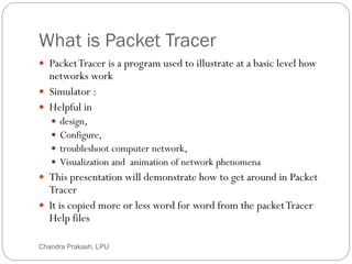
What is PacketTracer
2
PacketTracer is a program used to illustrate at a basic level how
networks work
Simulator :
Helpful in
design,
Configure,
troubleshoot computer network,
Visualization and animation of network phenomena
This presentation will demonstrate how to get around in Packet
Tracer
It is copied more or less word for word from the packetTracer
Help files
Chandra Prakash, LPU
3.
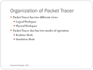
Organization of PacketTracer
3
PacketTracer has two different views
LogicalWorkspace
PhysicalWorkspace
PacketTracer also has two modes of operation
Realtime Mode
Simulation Mode
Chandra Prakash, LPU
4.
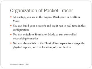
Organization of PacketTracer
4
At startup, you are in the LogicalWorkspace in Realtime
Mode
You can build your network and see it run in real time in this
configuration
You can switch to Simulation Mode to run controlled
networking scenarios
You can also switch to the PhysicalWorkspace to arrange the
physical aspects, such as location, of your devices
Chandra Prakash, LPU
5.
Organization of PacketTracer
5
You cannot run your network while you are in the Physical
Workspace
You should return to the LogicalWorkspace after you are
done in the PhysicalWorkspace
Chandra Prakash, LPU
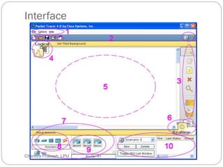
Menu Bar -1
8
This bar provides the File, Options, and Help menus
You will find basic commands such as Open, Save, Print, and
Preferences in these menus
You will also be able to access theActivityWizard from the
File menu
Chandra Prakash, LPU
9.
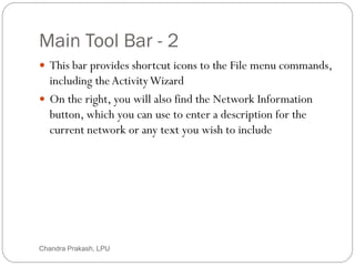
Main Tool Bar- 2
9
This bar provides shortcut icons to the File menu commands,
including theActivityWizard
On the right, you will also find the Network Information
button, which you can use to enter a description for the
current network or any text you wish to include
Chandra Prakash, LPU
10.
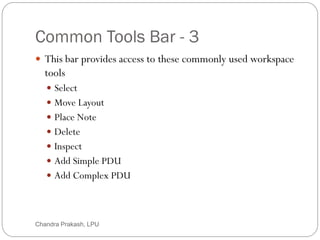
Common Tools Bar- 3
10
This bar provides access to these commonly used workspace
tools
Select
Move Layout
Place Note
Delete
Inspect
Add Simple PDU
Add Complex PDU
Chandra Prakash, LPU
11.
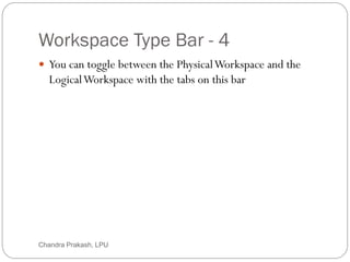
Workspace Type Bar- 4
11
You can toggle between the PhysicalWorkspace and the
LogicalWorkspace with the tabs on this bar
Chandra Prakash, LPU
12.
Workspace - 5
12
This area is where you will create your network, watch
simulations, and view many kinds of information and
statistics
Chandra Prakash, LPU
13.
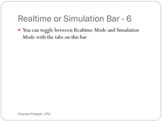
Realtime or SimulationBar - 6
13
You can toggle between Realtime Mode and Simulation
Mode with the tabs on this bar
Chandra Prakash, LPU
14.
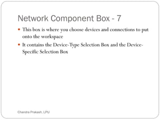
Network Component Box- 7
14
This box is where you choose devices and connections to put
onto the workspace
It contains the Device-Type Selection Box and the Device-
Specific Selection Box
Chandra Prakash, LPU
15.
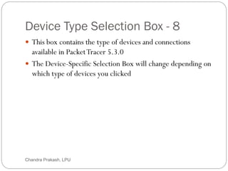
Device Type SelectionBox - 8
15
This box contains the type of devices and connections
available in PacketTracer 5.3.0
The Device-Specific Selection Box will change depending on
which type of devices you clicked
Chandra Prakash, LPU
16.
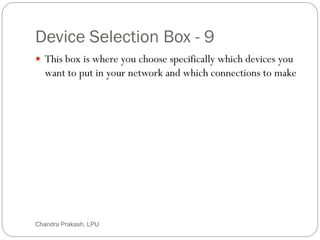
Device Selection Box- 9
16
This box is where you choose specifically which devices you
want to put in your network and which connections to make
Chandra Prakash, LPU
17.
Created Packet Window-10
17
This window manages the packets you put in the network
during simulation scenarios
Chandra Prakash, LPU
18.
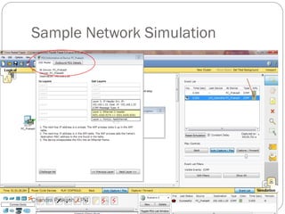
Sample Network Simulation
18
Let’s create a sample network to see how PacketTracer
simulates a network
Chandra Prakash, LPU
19.
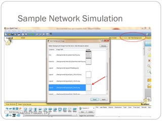
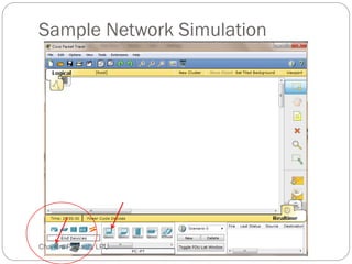
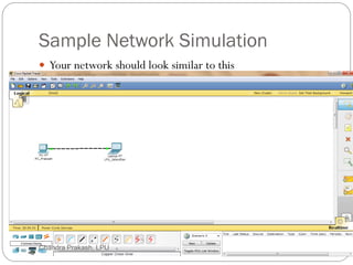
Sample Network Simulation
19
Start creating your network by loading a background grid
using the SetTiled Background button
Select the
grid_25x25.png
for this example
Chandra Prakash, LPU
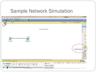
Sample Network Simulation
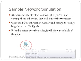
23
Always remember to close windows after you're done
viewing them, otherwise, they will clutter the workspace
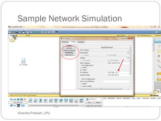
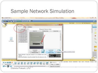
Open the PC's configuration window and change its settings
by going to the Config tab
Place the cursor over the device, it will show the details of
the node.
Chandra Prakash, LPU
Sample Network Simulation
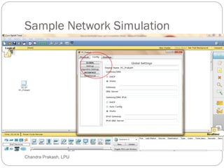
25
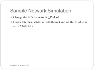
Change the PC's name to PC_Prakash
Under Interface, click on FastEthernet and set the IP address
as 192.168.1.15
Chandra Prakash, LPU
Sample Network Simulation
27
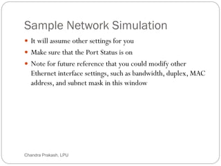
It will assume other settings for you
Make sure that the Port Status is on
Note for future reference that you could modify other
Ethernet interface settings, such as bandwidth, duplex, MAC
address, and subnet mask in this window
Chandra Prakash, LPU
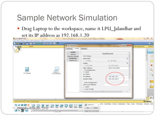
Sample Network Simulation
29
Drag Laptop to the workspace, name it LPU_Jalandhar and
set its IP address as 192.168.1.20
Chandra Prakash, LPU
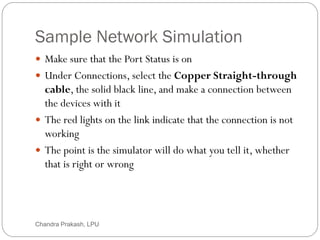
30.
Sample Network Simulation
30
Make sure that the Port Status is on
Under Connections, select the Copper Straight-through
cable, the solid black line, and make a connection between
the devices with it
The red lights on the link indicate that the connection is not
working
The point is the simulator will do what you tell it, whether
that is right or wrong
Chandra Prakash, LPU
31.
Sample Network Simulation
31
Now, using the Delete tool, remove the Copper Straight-through cable, and use a
Copper Cross-over cable instead
Straight-through cable is a type of twisted pair copper wire cable for local area
network (LAN) use for which the RJ-45 connectors at each end have the
same pinout (i.e., arrangement of conductors).
It is identical to crossover cable, except that in the latter the wires on the cable
are crossed over so that the receive signal pins on the connector on one end are
connected to the transmit signal pins on the connector on the other end.
Straight-through cable is also commonly referred to as patch cable. However, this might
be confusing in some situations because patch cable also has a broader definition that
emphasizes the fact that there is a connector on each end rather than the equality (or lack
thereof) of the pinouts.
Straight-through cable is used to connect computers and other end-user
devices (e.g., printers) to networking devices such as hubs and switches. It
can also be used to directly connect like devices (e.g., two hubs or two switches) if the
cable is plugged into an uplink port on one (but not both) of the devices.
Crossover cable is used to connect two like devices without the use of an
uplink port.
Chandra Prakash, LPU
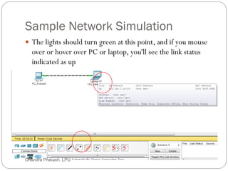
Sample Network Simulation
33
The lights should turn green at this point, and if you mouse
over or hover over PC or laptop, you'll see the link status
indicated as up
Chandra Prakash, LPU
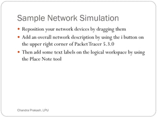
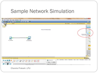
Sample Network Simulation
35
Reposition your network devices by dragging them
Add an overall network description by using the i button on
the upper right corner of PacketTracer 5.3.0
Then add some text labels on the logical workspace by using
the Place Note tool
Chandra Prakash, LPU
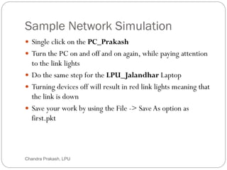
Sample Network Simulation
37
Single click on the PC_Prakash
Turn the PC on and off and on again, while paying attention
to the link lights
Do the same step for the LPU_Jalandhar Laptop
Turning devices off will result in red link lights meaning that
the link is down
Save your work by using the File -> Save As option as
first.pkt
Chandra Prakash, LPU
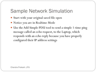
38.
Sample Network Simulation
38
Start with your original saved file open
Notice you are in Realtime Mode
Use theAdd Simple PDU tool to send a simple 1-time ping
message called an echo request, to the Laptop, which
responds with an echo reply because you have properly
configured their IP address settings
Chandra Prakash, LPU
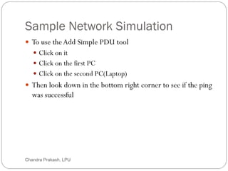
Sample Network Simulation
40
To use theAdd Simple PDU tool
Click on it
Click on the first PC
Click on the second PC(Laptop)
Then look down in the bottom right corner to see if the ping
was successful
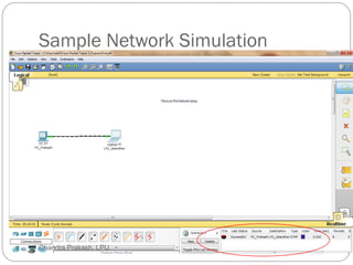
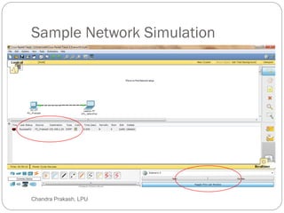
Chandra Prakash, LPU
Sample Network Simulation
42
Scroll around in the User Created PacketWindow to see the
different aspects of this ping message, including an indication
that the ping was successful
Alternatively, toggle the PDU ListWindow to see a larger
display of this message
Chandra Prakash, LPU
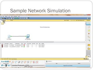
Sample Network Simulation
44
You can save one or more of these messages as a scenario
When you start, you are in Scenario 0
Label this first scenario with an i note
Different scenarios allow you to use the same topology for
experiments with different groupings of user created packets
Click on New to create a new scenario
Chandra Prakash, LPU
45.
Sample Network Simulation
45
New scenarios will always initially be blank
Add two packets by using the Simple PDU tool, perhaps a
PDU from PC_Prakash to LPU_Jalandhar and a different
PDU from LPU_Jalandhar to PC_Prakash
Then add a little i note describing the scenario, to complete
Scenario 1
An example is shown next
Chandra Prakash, LPU
Sample Network Simulation
47
Go back and forth between Scenario 0 and 1
Several different scenarios can be saved for a single network
Now delete Scenario 1 using the Delete button
You are back at Scenario 0
Chandra Prakash, LPU
48.
Sample Network Simulation
48
If you want to remove the PDU, you could scroll across in
the User Created PacketWindow and click on delete on the
last column
Do so
Delete the whole scenario
Chandra Prakash, LPU
49.
Sample Network Simulation
49
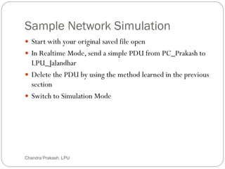
Start with your original saved file open
In Realtime Mode, send a simple PDU from PC_Prakash to
LPU_Jalandhar
Delete the PDU by using the method learned in the previous
section
Switch to Simulation Mode
Chandra Prakash, LPU
50.
Sample Network Simulation
50
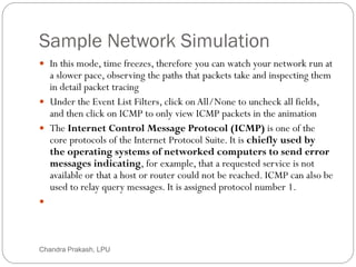
In this mode, time freezes, therefore you can watch your network run at
a slower pace, observing the paths that packets take and inspecting them
in detail packet tracing
Under the Event List Filters, click on All/None to uncheck all fields,
and then click on ICMP to only view ICMP packets in the animation
The Internet Control Message Protocol (ICMP) is one of the
core protocols of the Internet Protocol Suite. It is chiefly used by
the operating systems of networked computers to send error
messages indicating, for example, that a requested service is not
available or that a host or router could not be reached. ICMP can also be
used to relay query messages. It is assigned protocol number 1.
Chandra Prakash, LPU
51.
Sample Network Simulation
51
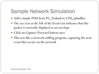
Add a simple PDU from PC_Prakash to LPU_jalandhar
The eye icon at the left of the Event List indicates that this
packet is currently displayed as an envelope
Click on Capture/Forward button once
This acts like a network sniffing program, capturing the next
event that occurs on the network
Chandra Prakash, LPU
52.
Sample Network Simulation
52
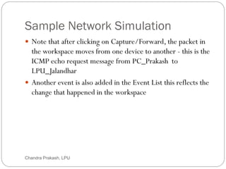
Note that after clicking on Capture/Forward, the packet in
the workspace moves from one device to another - this is the
ICMP echo request message from PC_Prakash to
LPU_Jalandhar
Another event is also added in the Event List this reflects the
change that happened in the workspace
Chandra Prakash, LPU
53.
Sample Network Simulation
53
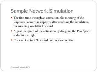
The first time through an animation, the meaning of the
Capture/Forward is Capture; after resetting the simulation,
the meaning would be Forward
Adjust the speed of the animation by dragging the Play Speed
slider to the right
Click on Capture/Forward button a second time
Chandra Prakash, LPU
54.
Sample Network Simulation
54
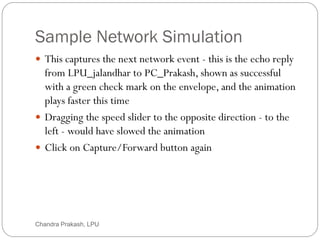
This captures the next network event - this is the echo reply
from LPU_jalandhar to PC_Prakash, shown as successful
with a green check mark on the envelope, and the animation
plays faster this time
Dragging the speed slider to the opposite direction - to the
left - would have slowed the animation
Click on Capture/Forward button again
Chandra Prakash, LPU
55.
Sample Network Simulation
55
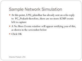
At this point, LPU_jalandhar has already sent an echo reply
to PC_Prakash therefore, there are no more ICMP events
left to capture
A No More Events window will appear notifying you of this,
as shown in the screenshot below
Click OK
Chandra Prakash, LPU
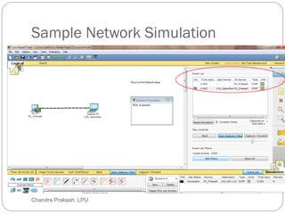
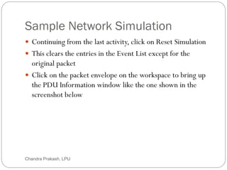
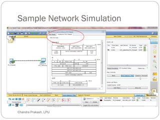
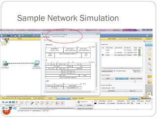
Sample Network Simulation
57
Continuing from the last activity, click on Reset Simulation
This clears the entries in the Event List except for the
original packet
Click on the packet envelope on the workspace to bring up
the PDU Information window like the one shown in the
screenshot below
Chandra Prakash, LPU
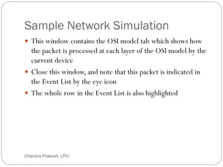
58.
Sample Network Simulation
58
This window contains the OSI model tab which shows how
the packet is processed at each layer of the OSI model by the
current device
Close this window, and note that this packet is indicated in
the Event List by the eye icon
The whole row in the Event List is also highlighted
Chandra Prakash, LPU
59.
Sample Network Simulation
59
For this row, clicking on the color square in the Info column
is equivalent to clicking directly on the packet envelope
Chandra Prakash, LPU
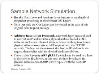
Sample Network Simulation
61
Use the Next Layer and Previous Layer buttons to see details of
the packet processing at the relevant OSI Layers
Note that only the Out Layers can be viewed in the case of this
original echo request message
Address Resolution Protocol, a network layer protocol used
to convert an IP address into a physical address (called a DLC
address), such as an Ethernet address.A host wishing to obtain a
physical addressbroadcasts anARP request onto theTCP/IP
network.The host on the network that has the IP address in the
request then replies with its physical hardware address.
There is also Reverse ARP (RARP) which can be used by a host
to discover its IP address. In this case, the host broadcasts its
physical address and a RARP server replies with the host's IP
address.
Chandra Prakash, LPU
62.
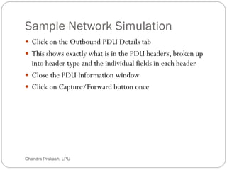
Sample Network Simulation
62
Click on the Outbound PDU Details tab
This shows exactly what is in the PDU headers, broken up
into header type and the individual fields in each header
Close the PDU Information window
Click on Capture/Forward button once
Chandra Prakash, LPU
Sample Network Simulation
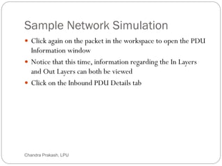
64
Click again on the packet in the workspace to open the PDU
Information window
Notice that this time, information regarding the In Layers
and Out Layers can both be viewed
Click on the Inbound PDU Details tab
Chandra Prakash, LPU
Sample Network Simulation
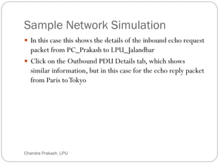
66
In this case this shows the details of the inbound echo request
packet from PC_Prakash to LPU_Jalandhar
Click on the Outbound PDU Details tab, which shows
similar information, but in this case for the echo reply packet
from Paris toTokyo
Chandra Prakash, LPU
67.
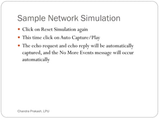
Sample Network Simulation
67
Click on Reset Simulation again
This time click onAuto Capture/Play
The echo request and echo reply will be automatically
captured, and the No More Events message will occur
automatically
Chandra Prakash, LPU
68.
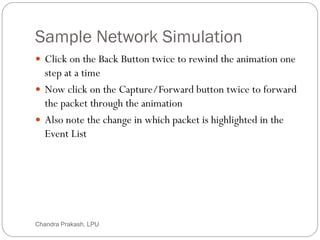
Sample Network Simulation
68
Click on the Back Button twice to rewind the animation one
step at a time
Now click on the Capture/Forward button twice to forward
the packet through the animation
Also note the change in which packet is highlighted in the
Event List
Chandra Prakash, LPU
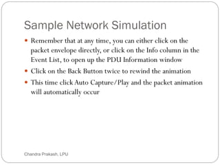
69.
Sample Network Simulation
69
Remember that at any time, you can either click on the
packet envelope directly, or click on the Info column in the
Event List, to open up the PDU Information window
Click on the Back Button twice to rewind the animation
This time click Auto Capture/Play and the packet animation
will automatically occur
Chandra Prakash, LPU
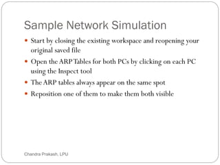
70.
Sample Network Simulation
70
Start by closing the existing workspace and reopening your
original saved file
Open theARPTables for both PCs by clicking on each PC
using the Inspect tool
TheARP tables always appear on the same spot
Reposition one of them to make them both visible
Chandra Prakash, LPU
71.
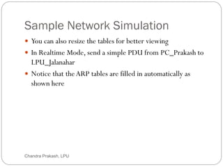
Sample Network Simulation
71
You can also resize the tables for better viewing
In Realtime Mode, send a simple PDU from PC_Prakash to
LPU_Jalanahar
Notice that theARP tables are filled in automatically as
shown here
Chandra Prakash, LPU
Sample Network Simulation
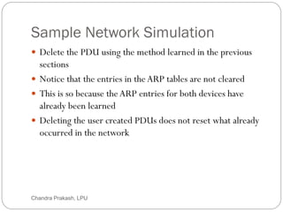
73
Delete the PDU using the method learned in the previous
sections
Notice that the entries in the ARP tables are not cleared
This is so because theARP entries for both devices have
already been learned
Deleting the user created PDUs does not reset what already
occurred in the network
Chandra Prakash, LPU
74.
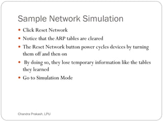
Sample Network Simulation
74
Click Reset Network
Notice that theARP tables are cleared
The Reset Network button power cycles devices by turning
them off and then on
By doing so, they lose temporary information like the tables
they learned
Go to Simulation Mode
Chandra Prakash, LPU
75.
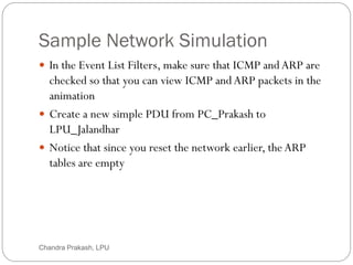
Sample Network Simulation
75
In the Event List Filters, make sure that ICMP andARP are
checked so that you can view ICMP andARP packets in the
animation
Create a new simple PDU from PC_Prakash to
LPU_Jalandhar
Notice that since you reset the network earlier, the ARP
tables are empty
Chandra Prakash, LPU
76.
Sample Network Simulation
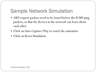
76
ARP request packets need to be issued before the ICMP ping
packets, so that the devices in the network can learn about
each other
Click onAuto Capture/Play to watch the animation
Click on Reset Simulation
Chandra Prakash, LPU
77.
Sample Network Simulation
77
Notice that even though the Event List is cleared - except for
the user created PDU, theARP tables still remain full
Click on Capture/Play
This time, since theARP tables are full, there are no new
ARP packets issued
Click on Reset Network
Doing so will empty the tables
Chandra Prakash, LPU
78.
Sample Network Simulation
78
Notice that a newARP request packet appears automatically
on the Event List
Single-clicking on the Delete button removes the entire
scenario including all the PDUs associated with it
Double-clicking on (delete) in the far right column in the
PDU List window deletes individual PDUs
Chandra Prakash, LPU
79.
Sample Network Simulation
79
The Reset Simulation button clears all entries in the Event
List, except for User Created PDUs, and allows you to
restart the animation
This, however, does not reset the device tables
The Reset Network button allows you to power-cycle all of
the devices in your network
Chandra Prakash, LPU
80.
Sample Network Simulation
80
It turns all devices off and then turns them back on so the
tables that the devices built are lost along with configurations
and other information not automatically saved
Saving your work periodically prevents you from losing
configurations and changes in the network that you want to
keep
Chandra Prakash, LPU