SlideShare a Scribd company logo
1 of 28
Site foundationwork
Site Kick Off day
The mainpurpose of this day isto identifyandconfirmthe site actual conditionwith the
customer’sparty.Afterthatconfirmation, contractorcantake to the necessaryactionto
arrange the boundary pegswithwarningtapes alongleasareaaccordingto the confirmedsite
layoutdrawings. Andalsoshoulddisplaythe safetysingboardsonthe sites.
 BenchMark
Benchmark generallydecidesonsite withboth partiesagreement,at onthe permanent
place.The mainpropose of benchmarkarrangement istomaintainthe site level
constancy until complete the task,andalsoaccordingto thisbenchmark level
contractor couldbe transferthe levelsondifferenceheights.
Please referbelowphotos
Boundary line Benchmark
Profile setting out withTL machine Safety sing boards
FoundationExcavation
General
Normal Soils foundations shall be excavated with excavator machines in suitable for cutting
soils and soft rocks such as shale, friable sandstone and limestone.
Site excavationstechnical methodscanbe differentbythe soilsconditions.
 Normal soils, softrockssuchas shale,friable sandstoneandlimestone shall be excavate
usingbyexcavatormachine.(excavationdepthneedreferwithBenchmark)
Rock blasting
BellowTechnical methodcan be used for compromise the soil erosion
and soil collapse
Retainingwalls
Coveredbank area
Brick retainingwall
Lean Preparation Casting
General
Afterexcavationworkcompletesite nextmilestone isleanconcrete,beforeleanconcrete everyworkers
shouldfollow below mentiontechnical methods.
1. ExcavationpitDimensionandDesigndetail drawingdimensionare equal.
2. Excavationdepthcheckwithsite benchmark
3. Excavationpitbedcompactionandstability
4. Lean concrete thickenscheckwithformworkheight.
Concrete ratiofor the lean casting1:3:6 (G20)
Necessaryarrangementduringthe leancastingtime
Needto test PH valueof water,Slump test,Testcubes, Rawmaterials qualityandrequirement
availability.
Aftercomplete thelean casting works.lean should be level and smooth.
Lean bed compaction using by compactor Lean casting
Rebar Setting Out
General
The main purpose of this technical method used to identify the correct locations in column centers and as well as
baseconcrete area.This setting out proceed by theodolite.
Rebar setting
Rebar Work
General
This re bar cutting and bending work process proceed in relativefabrication complex.After complete the cutting
and bending works warehouse management will distributes the rebar bundles respective site.
Duringthe rebar time, contractor should followbelowtechnical methods
1. Used to correct rebar diameter and length dimension accordingto the design drawing
2. Maintain the correct spacingin between the re bars
3. Maintain the mirror image
4. Maintain the correct lap length
5. Maintain the rebar clean from the rust
6. Maintain the correct covering
7. Maintain the correct heights of stools and quantities
 Rebar installation
Chemical anchoring
Above technical method mainly used for re arrangethe re bar on existingconcert or heard rock.
Concreting of Foundations
Afterrebarand formworkscomplete site nextmilestone isbase concrete,before base concrete every
workershouldfollow belowmentiontechnical methods.
1. DimensiontallywithDesigndetaildrawing.
2. Concrete thickenscheckwithformworkheight.
Concertratio dependinonstructural engineer’sspecification
Necessaryarrangementduringthe leancastingtime
Needto test PH valueof water,Slump test,Testcubes, Rawmaterials qualityandrequirement
availability.
Aftercomplete thebase casting works.baseshould belevel and smooth.Withoutany honeycomb,
curingshouldbe followasperthe specification(BritishStanderscodes)
Templates and Anchor Bolts Leveling
The mainlyexceptthistemplelevelingwork,toarrange the anchor boltsincorrect position,below
mentiontechnical requirementsformaintainthe duringwork
1. temple shouldfixwithcorrectmembers
2. template plate shouldbe positioninginequal level
3. All L Angelashouldsupportproperly
4. Anchorbolttop surface shouldlocate inequal level accordingtosite benchmark
5. All anchorbolts X and Y directionshouldvertical
6. Maintainthe columnsurface and anchorbolt heightaccordingto the towerspecificationdetails
Columns formwork and concreting
Aftertemplate workcomplete site nextmilestone iscolumnconcrete andformworks,beforecolumn
concrete everyworkershould follow below mentiontechnicalmethods.
1. Columndimensioncheckwithdetaildesigndrawing
2. Columnplumbandlevel
3. Formworkstrengthandstabilityforthe work
4. Necessarypropsandsupportsforthe columnformworks
5. Columncentertocenterdistance
6. Coveringbetweencolumnshutterworksandrebar
Concertratio dependinonstructural engineer’sspecification
Necessaryarrangementduringthe leancastingtime
Needto test PH valueof water,Slump test,Testcubes, Rawmaterials qualityandrequirement
availability.
Aftercomplete thecolumn casting works.column should belevel and smooth,withoutanyhoneycomb,
curingshouldbe followasperthe specification(BritishStanderscodes)
Backfilling
The backfill shall be placedinlayersnotexceeding200 mm thickand thoroughlycompactedusing
approvedcompactionequipment.
The finishedsurface of backfill shall be leftsmoothandshapedtocreate a watershedfromthe columns
area.
Equipment And DG slabcasting
Aftersite backfillingcompleteuptothe existinggroundlevel shallbe startthe equipmentandDG slab
concretingwork.Needtomaintainrequiredheightof slabsurface finishingusingbyBenchmark.
Testing inSite
 Water PH value testing
 Sumptest
 Cube casting
Test reports
Rebartest report
Tower Erection
Towererectionisthe secondmainpart of the project.Before startthe towererectionbelow mention
itemshouldbe concern
1. Towercollectingatthe warehouse –closely checkprovidedmembersandpackinglistare same
2. Transport - material transportbyverycarefullywithoutanydamages
3. Towermaterial onsite -members,nutsandbolts,washersandectsortingbysectionwise
4. Base plate placing– maintainthe gap betweencolumnsurface baseplate bottom(50mm-
70mm), base plate shouldplace oncorrectwasher, and all base plate shouldbe equal level.
5. Needtoarrange temporarygrounding
TowerBody erection
Tower nuts and bolts tighten shall be fix as per the bellow required Nm
Bolt type Nm
M12 Min27-Max30
M16 Min68-Max75
M20 Min132-Max147
M24 Min228-Max253
Lightingarrestand Aviationlampsfixing
 Life line anchorfixingcorrectly
Tower vertical check
Towervertical shall be checkusing theodolite andmaximumtoleranceneedtoH/400
Mm .Here H istowerheight.Shouldbe used2perpendicularfaces.
Usingtower2 legsdistance andneedtofindthe centerpoint.Afterthat theodoliteneedto
level andcoincide tothe centerpointandneedtotake offsetfix the woodenpegtomarkthe
alignpoint, requireddistance forthe checktowertop.Thenremove the theodolite andagain
needtolevel andcoincide newpeglocationsandneedalignprevioustower2 legscenterpoint
itsok needtofocusesbottom1st
cross plate centerpointsandneedtotake telescope until to
centerpoints checkingthe deviation.Whenreachthe towertop centerpointif have deviation
needtotheodolite crosscenterpointcoincide tothe towertopcenter usingHorizontal fine
screw . Againneedtocheck tower2 legscenterpointandneedto keepthe measuringtape
parallel centerpointandshall be readthe real deviationsandneedcheckopposite sitecenter
pointsalso.Usingcalculationsshall be identifyingthe towerdeviation. Abovestepsneedto
followremainperpendicularside also. If have detention inlimitationsokandnot needtoadjust
towerbase plate level untilverticallyok
Towergroutingwithconstructiongrout
Tower Grounding
Towergroundingworkisthe mainpart of the site safety.
Belowtechnical methodsfollowforproceedswork
1. Maintainthe minimumdistance betweencopperrod(4.5m)
2. Downconductor alwayslocate inopposite sideof the equipment
3. all connectionjointsshouldbe properlytighten
4. busbar(ECB) connectionnutsshouldbe non-corrodedironmade
5. A separate groundingnetworksshouldnotacross eachand others
6. Earth resistance shouldbe lessthan5 ohm
Fence Work
After compete tower erections and earthing work shall be start the fencing work to protect in site
area
 Fence setting out shall be arranged the following provided details drawing and need to
take fence beam finishing level using the bench mark.
 Fence Lean casting – need to follow provide drawing lean thickness.
Site Access road
Site accessroad shall be buildwhendifficultto enteringtothe site.Needtofollowthe detailsin
providingdetailsdrawingforthe accessroad.
 Bridge accessRoad
Site FATWork
Aftersite PATworkcomplete shall be arrange the FATinspections
 Completedsite
PAT and FAT accepted document

More Related Content

What's hot

Lecture 5 s.s.iii Design of Steel Structures - Faculty of Civil Engineering Iaşi
Lecture 5 s.s.iii Design of Steel Structures - Faculty of Civil Engineering IaşiLecture 5 s.s.iii Design of Steel Structures - Faculty of Civil Engineering Iaşi
Lecture 5 s.s.iii Design of Steel Structures - Faculty of Civil Engineering Iaşi
Ursachi Răzvan
 
Micro Piles Soil Nails
Micro Piles Soil NailsMicro Piles Soil Nails
Micro Piles Soil Nails
jamieram
 
Industrial Training Report-(2012-13)
Industrial Training Report-(2012-13)Industrial Training Report-(2012-13)
Industrial Training Report-(2012-13)
AJAY SHAHU
 
Linear guide roller bearing
Linear guide roller bearingLinear guide roller bearing
Linear guide roller bearing
Vicky Chou
 
Slope Stability Measure For Basement Excavation, A Case Study on Office Build...
Slope Stability Measure For Basement Excavation, A Case Study on Office Build...Slope Stability Measure For Basement Excavation, A Case Study on Office Build...
Slope Stability Measure For Basement Excavation, A Case Study on Office Build...
Andy Sugianto
 

What's hot (20)

Metso C series jaw crusher Manual
Metso C series jaw crusher  ManualMetso C series jaw crusher  Manual
Metso C series jaw crusher Manual
 
Ntpc summer training 2017
Ntpc summer training 2017Ntpc summer training 2017
Ntpc summer training 2017
 
Setting out of building
Setting out of buildingSetting out of building
Setting out of building
 
Soil nailing
Soil nailing Soil nailing
Soil nailing
 
Work check list
Work check listWork check list
Work check list
 
Lecture 5 s.s.iii Design of Steel Structures - Faculty of Civil Engineering Iaşi
Lecture 5 s.s.iii Design of Steel Structures - Faculty of Civil Engineering IaşiLecture 5 s.s.iii Design of Steel Structures - Faculty of Civil Engineering Iaşi
Lecture 5 s.s.iii Design of Steel Structures - Faculty of Civil Engineering Iaşi
 
Measurements in construction
Measurements in constructionMeasurements in construction
Measurements in construction
 
Stair core
Stair coreStair core
Stair core
 
McGill Metric CAMROL Bearings brochure
McGill Metric CAMROL Bearings brochureMcGill Metric CAMROL Bearings brochure
McGill Metric CAMROL Bearings brochure
 
Mcgill dealer in india vardhman bearings www.vardhmanbearings.com
Mcgill dealer  in india  vardhman bearings www.vardhmanbearings.comMcgill dealer  in india  vardhman bearings www.vardhmanbearings.com
Mcgill dealer in india vardhman bearings www.vardhmanbearings.com
 
Column base plates_prof_thomas_murray
Column base plates_prof_thomas_murrayColumn base plates_prof_thomas_murray
Column base plates_prof_thomas_murray
 
Allan block Installation guide
Allan block Installation guideAllan block Installation guide
Allan block Installation guide
 
Micro Piles Soil Nails
Micro Piles Soil NailsMicro Piles Soil Nails
Micro Piles Soil Nails
 
Form Work
Form Work Form Work
Form Work
 
Insert some activities into primavera p6
Insert some activities into primavera p6Insert some activities into primavera p6
Insert some activities into primavera p6
 
IS 4326
IS 4326IS 4326
IS 4326
 
Industrial Training Report-(2012-13)
Industrial Training Report-(2012-13)Industrial Training Report-(2012-13)
Industrial Training Report-(2012-13)
 
Linear guide roller bearing
Linear guide roller bearingLinear guide roller bearing
Linear guide roller bearing
 
Slope Stability Measure For Basement Excavation, A Case Study on Office Build...
Slope Stability Measure For Basement Excavation, A Case Study on Office Build...Slope Stability Measure For Basement Excavation, A Case Study on Office Build...
Slope Stability Measure For Basement Excavation, A Case Study on Office Build...
 
Industrial project report ppt CIVIL ENGINEERING
Industrial project report ppt CIVIL ENGINEERINGIndustrial project report ppt CIVIL ENGINEERING
Industrial project report ppt CIVIL ENGINEERING
 

Similar to Tower technical requirement repoart 022

Bored cast insitu
Bored cast insituBored cast insitu
Bored cast insitu
LingWei11
 
3141901-chapter-1_introduction-to-metrology-linear-and-angular-measurement.pdf
3141901-chapter-1_introduction-to-metrology-linear-and-angular-measurement.pdf3141901-chapter-1_introduction-to-metrology-linear-and-angular-measurement.pdf
3141901-chapter-1_introduction-to-metrology-linear-and-angular-measurement.pdf
Khalil Alhatab
 
98f5ce56 bca9-41ef-b8c9-095d7bf17a1c-151202050517-lva1-app6891
98f5ce56 bca9-41ef-b8c9-095d7bf17a1c-151202050517-lva1-app689198f5ce56 bca9-41ef-b8c9-095d7bf17a1c-151202050517-lva1-app6891
98f5ce56 bca9-41ef-b8c9-095d7bf17a1c-151202050517-lva1-app6891
AkashPatel747
 
Coupler (08102015)
Coupler (08102015)Coupler (08102015)
Coupler (08102015)
Khairul Amri
 

Similar to Tower technical requirement repoart 022 (20)

Bored cast insitu
Bored cast insituBored cast insitu
Bored cast insitu
 
Construction Survey
Construction SurveyConstruction Survey
Construction Survey
 
ppt on sub structure construction.pptx
ppt on sub structure construction.pptxppt on sub structure construction.pptx
ppt on sub structure construction.pptx
 
Casting yard
Casting yardCasting yard
Casting yard
 
Tower inspection
Tower inspection Tower inspection
Tower inspection
 
Rock engineering and ground control
Rock engineering and ground controlRock engineering and ground control
Rock engineering and ground control
 
Concreting work
Concreting workConcreting work
Concreting work
 
Final_ppt_puneeth.pptx
Final_ppt_puneeth.pptxFinal_ppt_puneeth.pptx
Final_ppt_puneeth.pptx
 
3141901-chapter-1_introduction-to-metrology-linear-and-angular-measurement.pdf
3141901-chapter-1_introduction-to-metrology-linear-and-angular-measurement.pdf3141901-chapter-1_introduction-to-metrology-linear-and-angular-measurement.pdf
3141901-chapter-1_introduction-to-metrology-linear-and-angular-measurement.pdf
 
98f5ce56 bca9-41ef-b8c9-095d7bf17a1c-151202050517-lva1-app6891
98f5ce56 bca9-41ef-b8c9-095d7bf17a1c-151202050517-lva1-app689198f5ce56 bca9-41ef-b8c9-095d7bf17a1c-151202050517-lva1-app6891
98f5ce56 bca9-41ef-b8c9-095d7bf17a1c-151202050517-lva1-app6891
 
Construction basic SIP
Construction basic SIPConstruction basic SIP
Construction basic SIP
 
Coupler (08102015)
Coupler (08102015)Coupler (08102015)
Coupler (08102015)
 
Cswip welding inspection notes and questions
Cswip welding inspection notes and questionsCswip welding inspection notes and questions
Cswip welding inspection notes and questions
 
Twi cswip welding inspection notes and questions
Twi cswip welding inspection notes and questionsTwi cswip welding inspection notes and questions
Twi cswip welding inspection notes and questions
 
GDT CHAPTER 6- Location Tol.pdf
GDT CHAPTER 6- Location Tol.pdfGDT CHAPTER 6- Location Tol.pdf
GDT CHAPTER 6- Location Tol.pdf
 
Non destructive testing (Civil Engineering )
Non destructive testing (Civil Engineering )Non destructive testing (Civil Engineering )
Non destructive testing (Civil Engineering )
 
Board pile method
Board pile methodBoard pile method
Board pile method
 
Prefabricated Column
Prefabricated ColumnPrefabricated Column
Prefabricated Column
 
Introduction to machine maintinance and installation
Introduction to machine maintinance and installationIntroduction to machine maintinance and installation
Introduction to machine maintinance and installation
 
report of open web girder (railway)
report of open web girder (railway)report of open web girder (railway)
report of open web girder (railway)
 

Tower technical requirement repoart 022

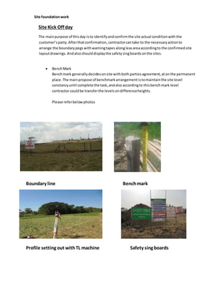
  • 1. Site foundationwork Site Kick Off day The mainpurpose of this day isto identifyandconfirmthe site actual conditionwith the customer’sparty.Afterthatconfirmation, contractorcantake to the necessaryactionto arrange the boundary pegswithwarningtapes alongleasareaaccordingto the confirmedsite layoutdrawings. Andalsoshoulddisplaythe safetysingboardsonthe sites.  BenchMark Benchmark generallydecidesonsite withboth partiesagreement,at onthe permanent place.The mainpropose of benchmarkarrangement istomaintainthe site level constancy until complete the task,andalsoaccordingto thisbenchmark level contractor couldbe transferthe levelsondifferenceheights. Please referbelowphotos Boundary line Benchmark Profile setting out withTL machine Safety sing boards
  • 2. FoundationExcavation General Normal Soils foundations shall be excavated with excavator machines in suitable for cutting soils and soft rocks such as shale, friable sandstone and limestone. Site excavationstechnical methodscanbe differentbythe soilsconditions.  Normal soils, softrockssuchas shale,friable sandstoneandlimestone shall be excavate usingbyexcavatormachine.(excavationdepthneedreferwithBenchmark) Rock blasting
  • 3. BellowTechnical methodcan be used for compromise the soil erosion and soil collapse Retainingwalls Coveredbank area
  • 5. Lean Preparation Casting General Afterexcavationworkcompletesite nextmilestone isleanconcrete,beforeleanconcrete everyworkers shouldfollow below mentiontechnical methods. 1. ExcavationpitDimensionandDesigndetail drawingdimensionare equal. 2. Excavationdepthcheckwithsite benchmark 3. Excavationpitbedcompactionandstability 4. Lean concrete thickenscheckwithformworkheight. Concrete ratiofor the lean casting1:3:6 (G20) Necessaryarrangementduringthe leancastingtime Needto test PH valueof water,Slump test,Testcubes, Rawmaterials qualityandrequirement availability. Aftercomplete thelean casting works.lean should be level and smooth. Lean bed compaction using by compactor Lean casting
  • 6. Rebar Setting Out General The main purpose of this technical method used to identify the correct locations in column centers and as well as baseconcrete area.This setting out proceed by theodolite. Rebar setting Rebar Work General This re bar cutting and bending work process proceed in relativefabrication complex.After complete the cutting and bending works warehouse management will distributes the rebar bundles respective site. Duringthe rebar time, contractor should followbelowtechnical methods 1. Used to correct rebar diameter and length dimension accordingto the design drawing 2. Maintain the correct spacingin between the re bars
  • 7. 3. Maintain the mirror image 4. Maintain the correct lap length 5. Maintain the rebar clean from the rust 6. Maintain the correct covering 7. Maintain the correct heights of stools and quantities  Rebar installation Chemical anchoring
  • 8. Above technical method mainly used for re arrangethe re bar on existingconcert or heard rock. Concreting of Foundations Afterrebarand formworkscomplete site nextmilestone isbase concrete,before base concrete every workershouldfollow belowmentiontechnical methods.
  • 9. 1. DimensiontallywithDesigndetaildrawing. 2. Concrete thickenscheckwithformworkheight. Concertratio dependinonstructural engineer’sspecification Necessaryarrangementduringthe leancastingtime Needto test PH valueof water,Slump test,Testcubes, Rawmaterials qualityandrequirement availability. Aftercomplete thebase casting works.baseshould belevel and smooth.Withoutany honeycomb, curingshouldbe followasperthe specification(BritishStanderscodes) Templates and Anchor Bolts Leveling The mainlyexceptthistemplelevelingwork,toarrange the anchor boltsincorrect position,below mentiontechnical requirementsformaintainthe duringwork
  • 10. 1. temple shouldfixwithcorrectmembers 2. template plate shouldbe positioninginequal level 3. All L Angelashouldsupportproperly 4. Anchorbolttop surface shouldlocate inequal level accordingtosite benchmark 5. All anchorbolts X and Y directionshouldvertical 6. Maintainthe columnsurface and anchorbolt heightaccordingto the towerspecificationdetails Columns formwork and concreting
  • 11. Aftertemplate workcomplete site nextmilestone iscolumnconcrete andformworks,beforecolumn concrete everyworkershould follow below mentiontechnicalmethods. 1. Columndimensioncheckwithdetaildesigndrawing 2. Columnplumbandlevel 3. Formworkstrengthandstabilityforthe work 4. Necessarypropsandsupportsforthe columnformworks 5. Columncentertocenterdistance 6. Coveringbetweencolumnshutterworksandrebar Concertratio dependinonstructural engineer’sspecification Necessaryarrangementduringthe leancastingtime Needto test PH valueof water,Slump test,Testcubes, Rawmaterials qualityandrequirement availability. Aftercomplete thecolumn casting works.column should belevel and smooth,withoutanyhoneycomb, curingshouldbe followasperthe specification(BritishStanderscodes)
  • 12. Backfilling The backfill shall be placedinlayersnotexceeding200 mm thickand thoroughlycompactedusing approvedcompactionequipment.
  • 13. The finishedsurface of backfill shall be leftsmoothandshapedtocreate a watershedfromthe columns area. Equipment And DG slabcasting
  • 14. Aftersite backfillingcompleteuptothe existinggroundlevel shallbe startthe equipmentandDG slab concretingwork.Needtomaintainrequiredheightof slabsurface finishingusingbyBenchmark. Testing inSite  Water PH value testing
  • 15.  Sumptest  Cube casting Test reports
  • 17. Towererectionisthe secondmainpart of the project.Before startthe towererectionbelow mention itemshouldbe concern 1. Towercollectingatthe warehouse –closely checkprovidedmembersandpackinglistare same 2. Transport - material transportbyverycarefullywithoutanydamages 3. Towermaterial onsite -members,nutsandbolts,washersandectsortingbysectionwise 4. Base plate placing– maintainthe gap betweencolumnsurface baseplate bottom(50mm- 70mm), base plate shouldplace oncorrectwasher, and all base plate shouldbe equal level. 5. Needtoarrange temporarygrounding TowerBody erection
  • 18. Tower nuts and bolts tighten shall be fix as per the bellow required Nm
  • 19. Bolt type Nm M12 Min27-Max30 M16 Min68-Max75 M20 Min132-Max147 M24 Min228-Max253 Lightingarrestand Aviationlampsfixing
  • 20.  Life line anchorfixingcorrectly
  • 21. Tower vertical check Towervertical shall be checkusing theodolite andmaximumtoleranceneedtoH/400 Mm .Here H istowerheight.Shouldbe used2perpendicularfaces. Usingtower2 legsdistance andneedtofindthe centerpoint.Afterthat theodoliteneedto level andcoincide tothe centerpointandneedtotake offsetfix the woodenpegtomarkthe alignpoint, requireddistance forthe checktowertop.Thenremove the theodolite andagain needtolevel andcoincide newpeglocationsandneedalignprevioustower2 legscenterpoint itsok needtofocusesbottom1st cross plate centerpointsandneedtotake telescope until to centerpoints checkingthe deviation.Whenreachthe towertop centerpointif have deviation needtotheodolite crosscenterpointcoincide tothe towertopcenter usingHorizontal fine screw . Againneedtocheck tower2 legscenterpointandneedto keepthe measuringtape parallel centerpointandshall be readthe real deviationsandneedcheckopposite sitecenter pointsalso.Usingcalculationsshall be identifyingthe towerdeviation. Abovestepsneedto followremainperpendicularside also. If have detention inlimitationsokandnot needtoadjust towerbase plate level untilverticallyok Towergroutingwithconstructiongrout
  • 22. Tower Grounding Towergroundingworkisthe mainpart of the site safety. Belowtechnical methodsfollowforproceedswork 1. Maintainthe minimumdistance betweencopperrod(4.5m) 2. Downconductor alwayslocate inopposite sideof the equipment 3. all connectionjointsshouldbe properlytighten 4. busbar(ECB) connectionnutsshouldbe non-corrodedironmade 5. A separate groundingnetworksshouldnotacross eachand others 6. Earth resistance shouldbe lessthan5 ohm
  • 23.
  • 24. Fence Work After compete tower erections and earthing work shall be start the fencing work to protect in site area  Fence setting out shall be arranged the following provided details drawing and need to take fence beam finishing level using the bench mark.  Fence Lean casting – need to follow provide drawing lean thickness.
  • 25.
  • 26. Site Access road Site accessroad shall be buildwhendifficultto enteringtothe site.Needtofollowthe detailsin providingdetailsdrawingforthe accessroad.  Bridge accessRoad
  • 27. Site FATWork Aftersite PATworkcomplete shall be arrange the FATinspections  Completedsite
  • 28. PAT and FAT accepted document