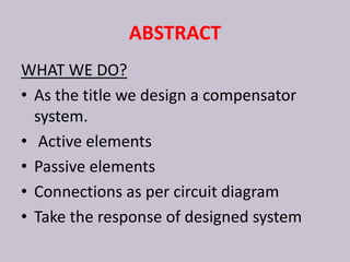
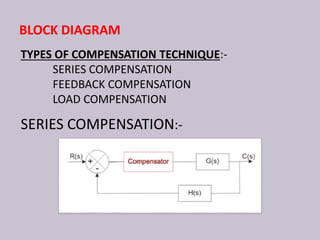
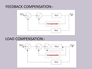
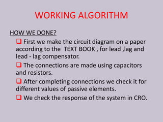
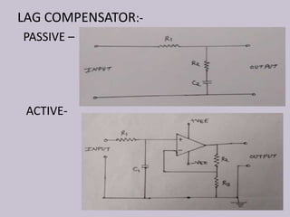
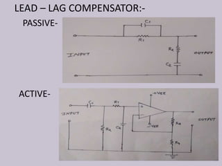
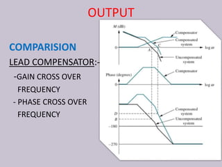
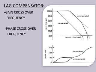
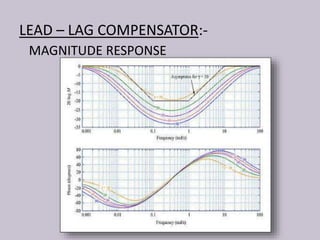
TO DEVELOPE AND DESIGN
COMPENSATOR SYSTEM
SUBMITTED TO:-
Dr. JK DEEGWAL (HOD -EIC)
Dr. C.P.JAIN (Asst. Prof.)
Mr. RAJ KUMAR YADAV (Asst. Prof.)
SUBMITTED BY:-
VISHNU KUMAR SHARMA
PRADEEP KUMAR PATIDAR
GOVERNMENT ENGINEERING COLLEGE
AJMER
DEPARTMENT
ELECTRONICS INSTRUMENTATION &CONTROL
ENGINEERING
PRESENTATION OVERVIEW
• ABSTRACT
• INTRODUCTION OF PROJECT
• LITERATURE REVIEW
• WORKING ALGORITHM
• OUTPUT
• CONCLUSION
• APPLICATION
• REFERENCE
ABSTRACT
WHAT WE DO?
• As the title we design a compensator
system.
• Active elements
• Passive elements
• Connections as per circuit diagram
• Take the response of designed system
INTRODUCTION OF PROJECT
 This project is useful to obtain the desired performance of the
system .
 This project is based on the use of compensators in control
systems.
 In this project we design the compensators like lead
compensator ,lag compensator and lead-lag compensator.
 Compensation is an important technique in control system
design.
BLOCK DIAGRAM
TYPES OF COMPENSATION TECHNIQUE:-
SERIES COMPENSATION
FEEDBACK COMPENSATION
LOAD COMPENSATION
SERIES COMPENSATION:-
FEEDBACK COMPENSATION:-
LOAD COMPENSATION:-
LITERATURE REVIEW
WHAT HAS BEEN DONE IN EARLIER ?
 Before compensator we were use simple
feedback topologies for improving stability of a
system .
 Generally negative feedback is used.
 After developing compensator system stability of
a system is increases precisely .
WORKING ALGORITHM
HOW WE DONE?
 First we make the circuit diagram on a paper
according to the TEXT BOOK , for lead ,lag and
lead - lag compensator.
 The connections are made using capacitors
and resistors.
 After completing connections we check it for
different values of passive elements.
 We check the response of the system in CRO.
LEAD COMPENSATOR:-
PASSIVE –
ACTIVE-
LAG COMPENSATOR:-
PASSIVE –
ACTIVE-
LEAD – LAG COMPENSATOR:-
PASSIVE-
ACTIVE-
DESIGNED SYSTEM TOP VIEW
OUTPUT
COMPARISION
LEAD COMPENSATOR:-
-GAIN CROSS OVER
FREQUENCY
- PHASE CROSS OVER
FREQUENCY
LAG COMPENSATOR:-
-GAIN CROSS OVER
FREQUENCY
-PHASE CROSS OVER
FREQUENCY
LEAD – LAG COMPENSATOR:-
MAGNITUDE RESPONSE
CONCLUSION
EFFECT OF COMPENSATOR
SOME OTHER EFFECT:-
EFFECT OF JITA(ξ):-
APPLICATION
Lead–lag compensators influence disciplines
as varied as robotics , automobile diagnostics.
They are an important building block in analog
control systems, and can also be used in digital
control.
REFERENCE
 J. U. Duncombe, "Infrared navigation - Part I: An
assessment of feasibility," IEEE Transactions on
Electron Devices, vol. ED-11, pp. 34-39, Jan. 1959.
 M.-Y. Chow, Y Tipsuwan, "Time sensitive network-
based control systems and applications", IEEE IES
Newts. Based Control Newsletter., vol. 5, no. 2, pp.
13-18, Jun. 2005.
 Https://allenlu2007.Wordpress.Com/2015/05/30/opa
mp-compensation-gain-reduction-lead-lead-lag/
THANK YOU

To develope and design compensator system

  • 1.
    TO DEVELOPE ANDDESIGN COMPENSATOR SYSTEM SUBMITTED TO:- Dr. JK DEEGWAL (HOD -EIC) Dr. C.P.JAIN (Asst. Prof.) Mr. RAJ KUMAR YADAV (Asst. Prof.) SUBMITTED BY:- VISHNU KUMAR SHARMA PRADEEP KUMAR PATIDAR GOVERNMENT ENGINEERING COLLEGE AJMER DEPARTMENT ELECTRONICS INSTRUMENTATION &CONTROL ENGINEERING
  • 2.
    PRESENTATION OVERVIEW • ABSTRACT •INTRODUCTION OF PROJECT • LITERATURE REVIEW • WORKING ALGORITHM • OUTPUT • CONCLUSION • APPLICATION • REFERENCE
  • 3.
    ABSTRACT WHAT WE DO? •As the title we design a compensator system. • Active elements • Passive elements • Connections as per circuit diagram • Take the response of designed system
  • 4.
    INTRODUCTION OF PROJECT This project is useful to obtain the desired performance of the system .  This project is based on the use of compensators in control systems.  In this project we design the compensators like lead compensator ,lag compensator and lead-lag compensator.  Compensation is an important technique in control system design.
  • 5.
    BLOCK DIAGRAM TYPES OFCOMPENSATION TECHNIQUE:- SERIES COMPENSATION FEEDBACK COMPENSATION LOAD COMPENSATION SERIES COMPENSATION:-
  • 6.
  • 7.
    LITERATURE REVIEW WHAT HASBEEN DONE IN EARLIER ?  Before compensator we were use simple feedback topologies for improving stability of a system .  Generally negative feedback is used.  After developing compensator system stability of a system is increases precisely .
  • 8.
    WORKING ALGORITHM HOW WEDONE?  First we make the circuit diagram on a paper according to the TEXT BOOK , for lead ,lag and lead - lag compensator.  The connections are made using capacitors and resistors.  After completing connections we check it for different values of passive elements.  We check the response of the system in CRO.
  • 9.
  • 10.
  • 11.
    LEAD – LAGCOMPENSATOR:- PASSIVE- ACTIVE-
  • 12.
  • 13.
    OUTPUT COMPARISION LEAD COMPENSATOR:- -GAIN CROSSOVER FREQUENCY - PHASE CROSS OVER FREQUENCY
  • 14.
    LAG COMPENSATOR:- -GAIN CROSSOVER FREQUENCY -PHASE CROSS OVER FREQUENCY
  • 15.
    LEAD – LAGCOMPENSATOR:- MAGNITUDE RESPONSE
  • 16.
  • 17.
  • 18.
    APPLICATION Lead–lag compensators influencedisciplines as varied as robotics , automobile diagnostics. They are an important building block in analog control systems, and can also be used in digital control.
  • 19.
    REFERENCE  J. U.Duncombe, "Infrared navigation - Part I: An assessment of feasibility," IEEE Transactions on Electron Devices, vol. ED-11, pp. 34-39, Jan. 1959.  M.-Y. Chow, Y Tipsuwan, "Time sensitive network- based control systems and applications", IEEE IES Newts. Based Control Newsletter., vol. 5, no. 2, pp. 13-18, Jun. 2005.  Https://allenlu2007.Wordpress.Com/2015/05/30/opa mp-compensation-gain-reduction-lead-lead-lag/
  • 20.