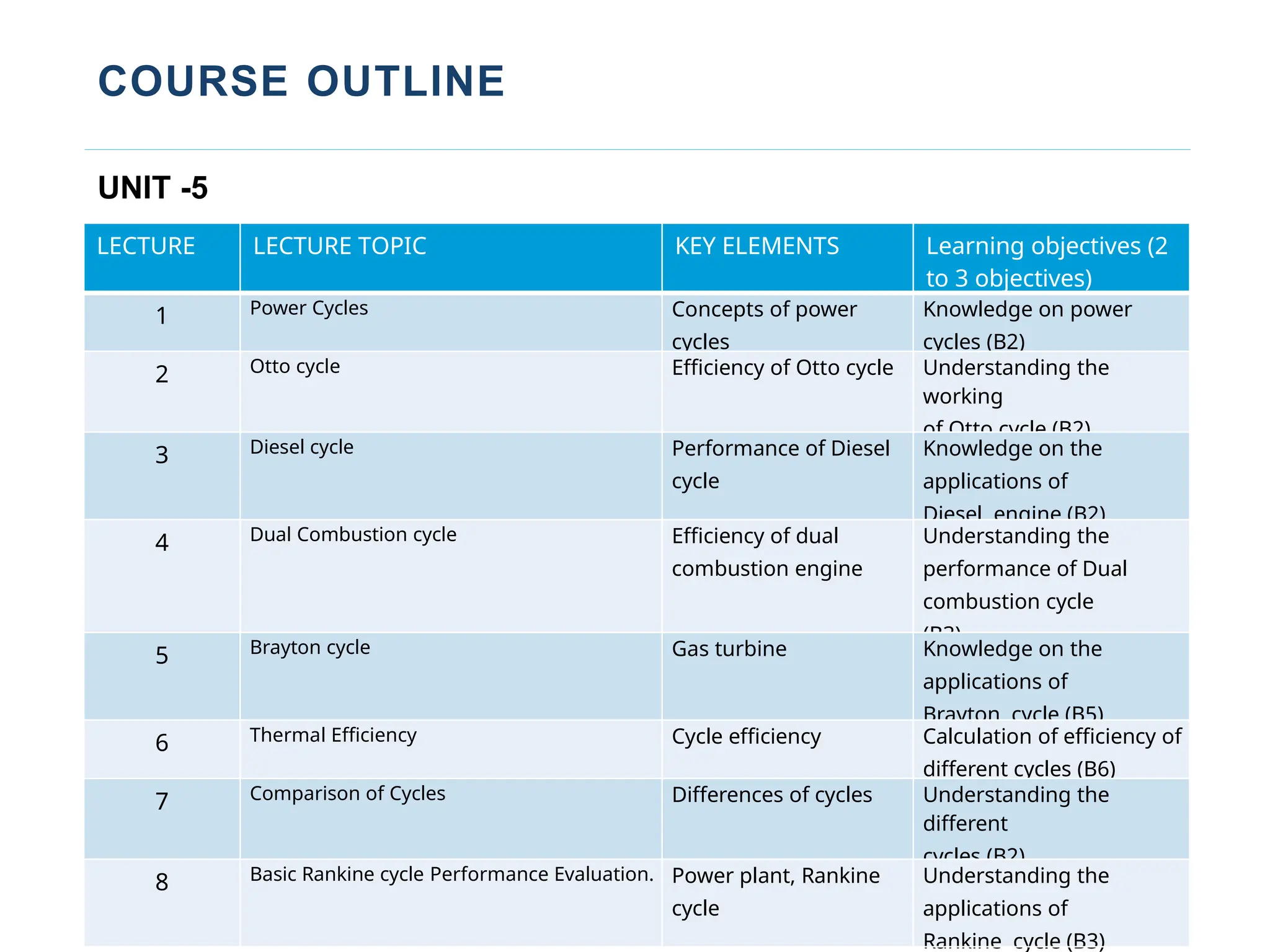
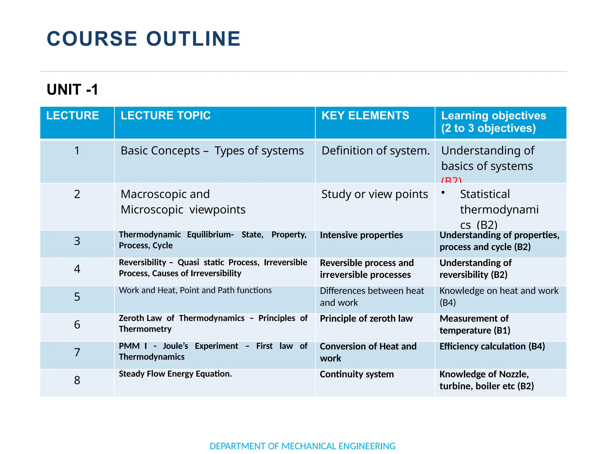
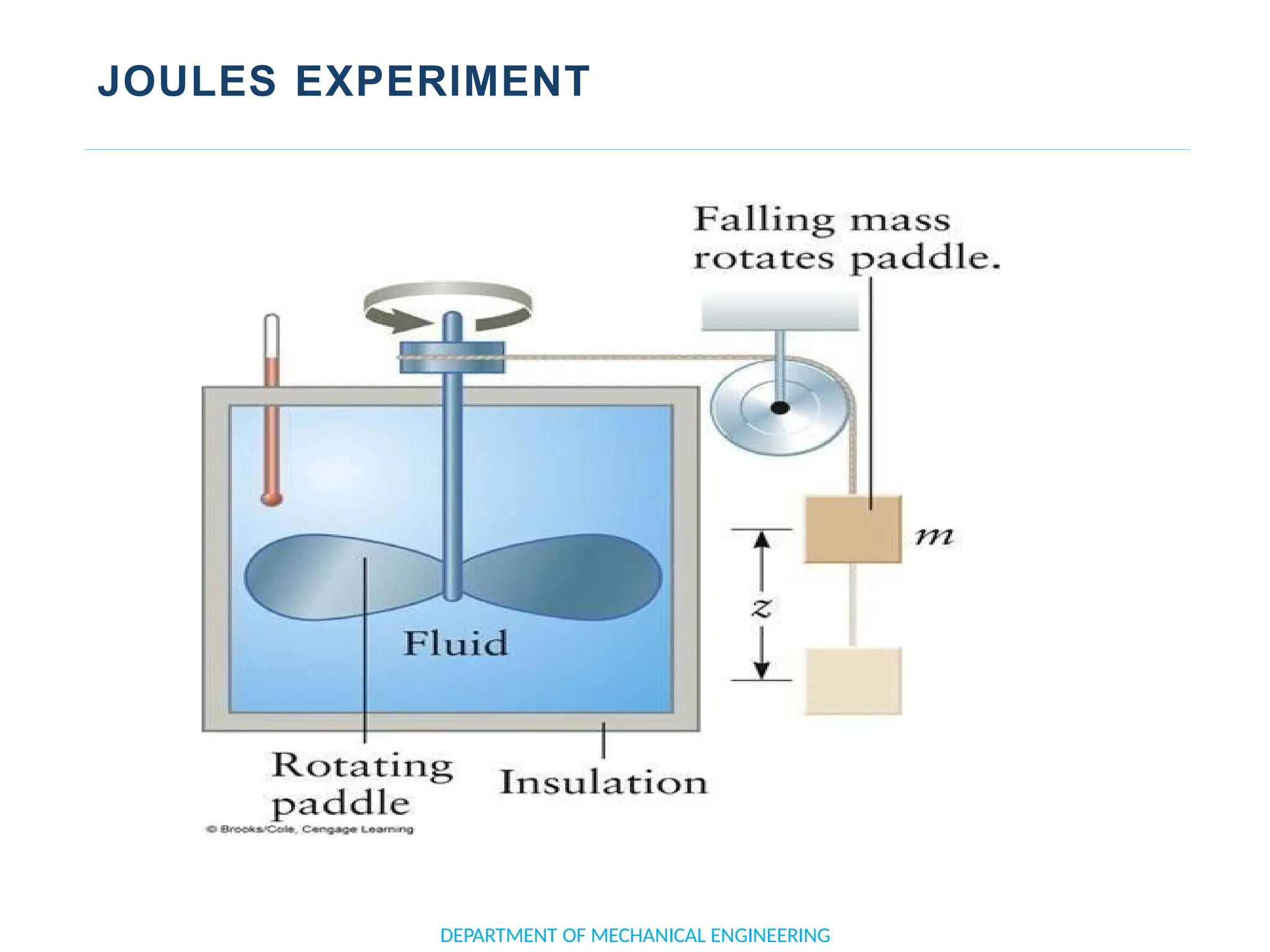
The document outlines the course objectives and content of an engineering thermodynamics program, covering fundamental concepts such as energy transformation, thermodynamic laws, and properties of systems. It details various types of thermodynamic processes and cycles, including definitions of closed, open, and isolated systems, as well as reversible and irreversible processes. Additionally, it addresses the zeroth law of thermodynamics, principles of thermometry, and the first law of thermodynamics through practical examples like Joule's experiment.

![APPLICATION OF FIRST LAW TO A PROCESS
• When a process is executed by a system,
the change in stored energy of the system is
numerically equal to the net heat interactions
minus the net work interaction during the
process.
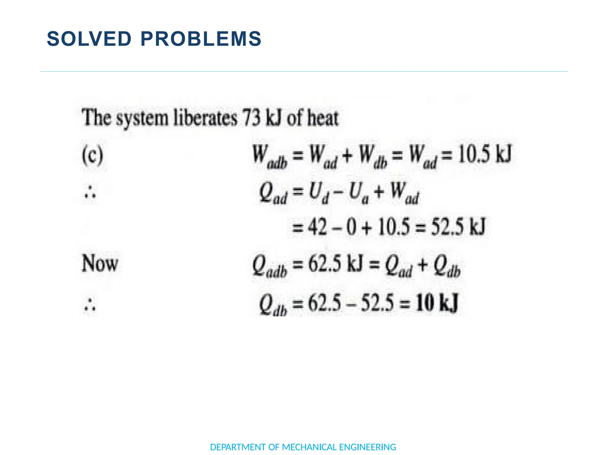
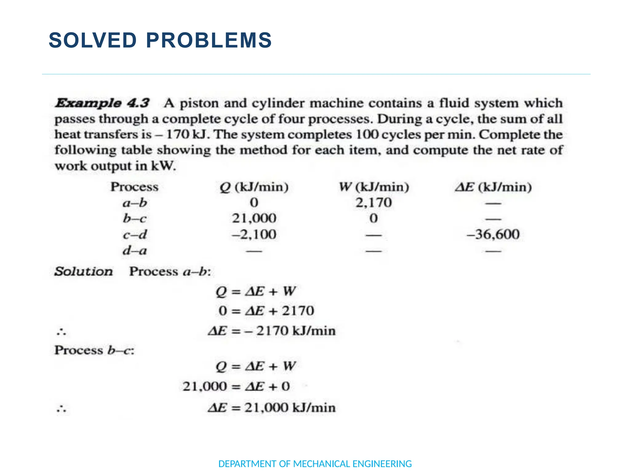
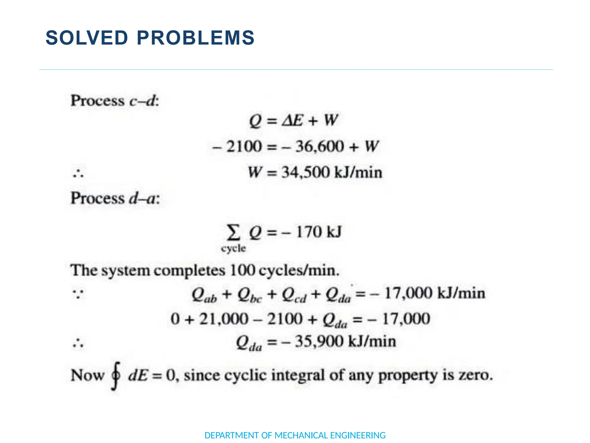
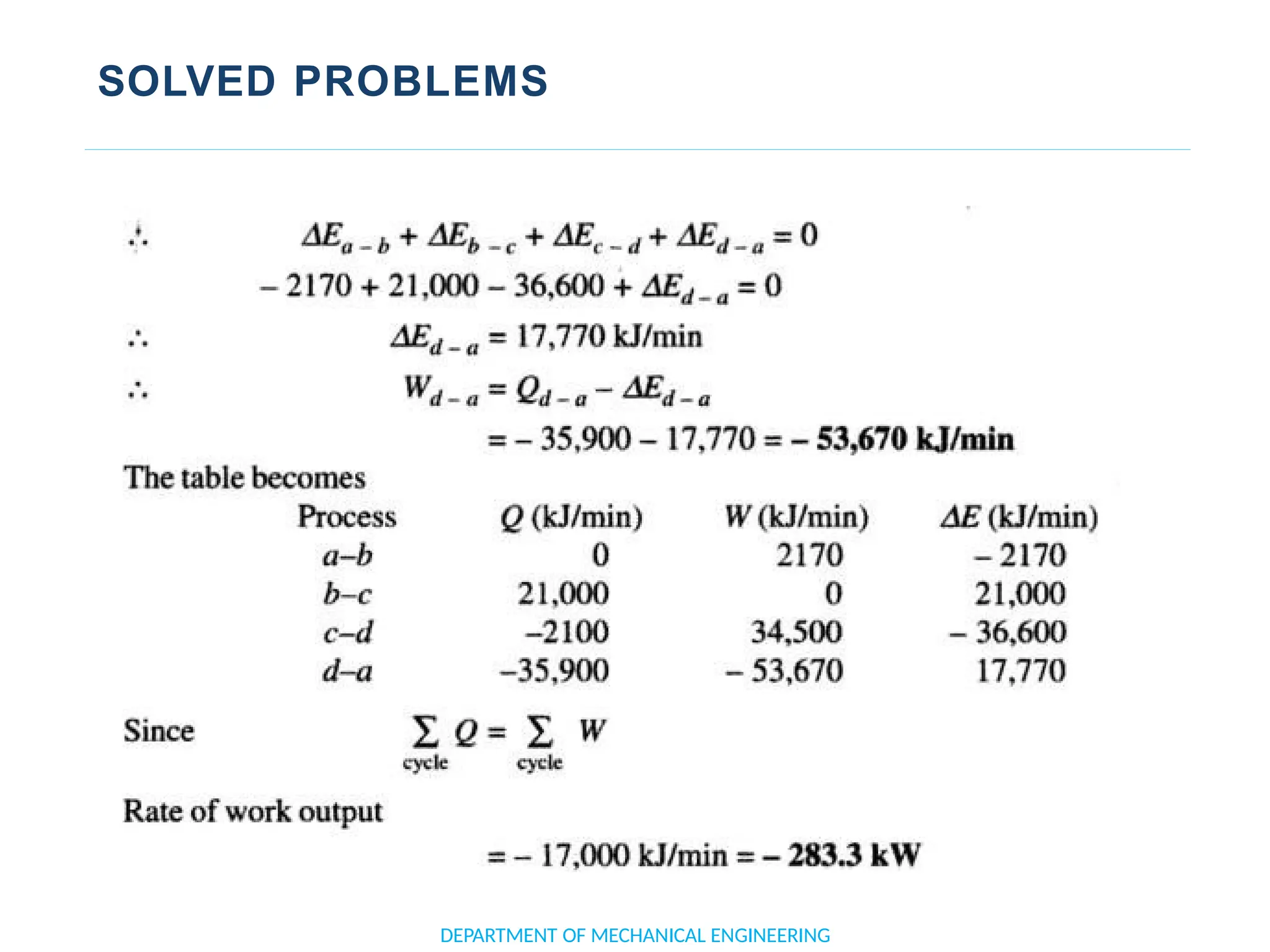
• ∴ E2 – E1 = Q – W
• ∴ ΔE = Q – W [or Q = Δ E + W]
• Or d(Q −W) 12 = Δ E = E2 – E1
• Where E represents the total internal
energy.
DEPARTMENT OF MECHANICAL ENGINEERING](https://image.slidesharecdn.com/thermodynamicsdigitalmaterial-241018153449-4ab9e18c/75/Thermodynamics-Digital-Material-complete-course-61-2048.jpg)