Download to read offline

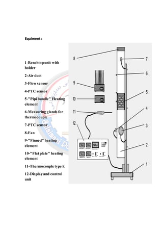

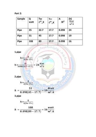


1. This document describes a laboratory experiment on thermal convection. The experiment uses a benchtop unit with an air duct, heating elements of different shapes, and sensors to study free and forced convection. 2. Calculations are shown to determine the heat transfer coefficient (h) for flat, pipe bundle, and fin-shaped heating elements. The h value is highest for the fin-shaped element and lowest for the flat element. 3. The conclusion states that different materials and heating element designs have varying heat transfer coefficients, which provides insight into how long it takes different objects to cool from the inside out.


