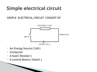
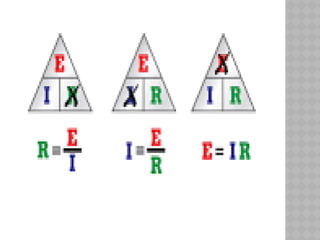
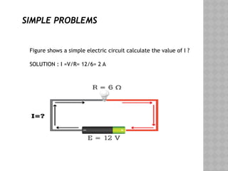
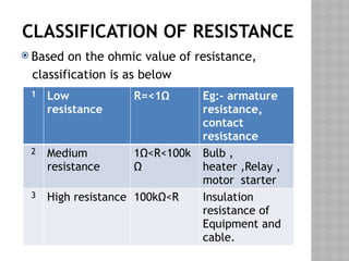
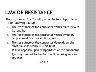
OHMS LAW
ati calicut
OBJECTIVES
 Definitions of emf ,P.D ,Voltage , current and
resistance.
 Relation between these terms in a simple
electrical circuit
 OHM’S law
 Laws of resistance
 Classification of resistance
 Definition of Specific resistance
SIMPLE ELECTRICAL CIRCUIT CONSIST OF
 An Energy Source ( Cell )
 Conductor
 A load ( Resistor )
 A control device ( Switch )
Simple electrical circuit
DEFINITIONS OF ELECTRICAL
TERMS
 CURRENT
 ELECTRIC CHARGE
 EMF
 POTENTIAL DIFFERENCE
 RESISTANCE
 CONDUCTANCE
 POWER
 ENERGY
CURRENT
 The flow of electrons in one direction along
any path or around any circuit is called
electric current.
 Its symbol is I and its unit s ampere (A).
 The instrument which is used to measure
current is called ‘AMMETER’ ,which is always
connected in series with the circuit.
ELECTRO MOTIVE FORCE ( EMF )
 The force which causes current to flow in
the circuit is called EMF.
 Its symbol is E and is measured in volts(V)The
EMF of an electrical source may be referred
as its voltage.
 EMF can be calculated as
EMF=voltage at the terminal of the source of
supply + voltage drop in the supply source
EMF=VT+IR
POTENTIAL DIFFERENCE
 The difference of electrical potential
between two points in an electric circuit.
 Its always less than EMF.
 Its symbol is V and is also measured in volts.
 The instrument that measure the P.D. is
called ‘ VOLTMETER ’. It is always connected
in
parallel with the circuit whose voltage is to
be measured.
CONDUCTANCE
 The property of a conductor to conduct
electricity is called conductance.
 Its symbol is G
 It unit is ‘mho’
 Good conductors have good conductance.
RESISTANCE
 The property of a material to oppose the
flow of electric current through them is
called resistance.
 The resistance of each material is depend
upon its composition, length, area and
temperature.
 Its unit is ohm (Ω).
PICTORIAL REPRESENTATION OF
EMF , CURRENT & RESISTANCE
OHM’S LAW
G .S . Ohm established this law which gives the relation
between current , voltage and resistance in a closed
electric circuit.
OHM’s law states that: “ in
a closed circuit the current(I) flowing through a
conductor at constant temperature is directly
proportional to the voltage(V) across the conductor
and inversely proportional to its resistance(R)”.
I α V
I=V/R
OHM’S TRIANGLE

SIMPLE PROBLEMS
Figure shows a simple electric circuit calculate the value of I ?
SOLUTION : I =V/R= 12/6= 2 A
CLASSIFICATION OF RESISTANCE
 Based on the ohmic value of resistance,
classification is as below
1 Low
resistance
R=<1Ω Eg:- armature
resistance,
contact
resistance
2 Medium
resistance
1Ω<R<100k
Ω
Bulb ,
heater ,Relay ,
motor starter
3 High resistance 100kΩ<R Insulation
resistance of
Equipment and
cable.
LAW OF RESISTANCE
The resistance ,R offered by a conductors depends on
the following factors
1. The resistance of the conductor varies directly with
its length.
2. The resistance of the conductor varies inversely
proportional to cross sectional area.
3. The resistance of the conductor depends on the
material with which it is made of
It also depends upon temperature of the conductor.
Ignoring the last factor for the time being we can
say that
R=ρ l/a
SPECIFIC RESISTANCE
SPECIFIC RESISTANCE (RESISTIVITY)
It may be defined as the resistance offered to
a current if passed between the opposite
faces of the unit cube of the material.
SUMMARY
We have learned about,
 A simple electric circuit
 Terms related to electric circuit
 Ohm’s law
 Laws of resistance
THANK YOU

theory ppt Ohms law explained by trainee.pptx

  • 1.
  • 2.
    OBJECTIVES  Definitions ofemf ,P.D ,Voltage , current and resistance.  Relation between these terms in a simple electrical circuit  OHM’S law  Laws of resistance  Classification of resistance  Definition of Specific resistance
  • 3.
    SIMPLE ELECTRICAL CIRCUITCONSIST OF  An Energy Source ( Cell )  Conductor  A load ( Resistor )  A control device ( Switch ) Simple electrical circuit
  • 4.
    DEFINITIONS OF ELECTRICAL TERMS CURRENT  ELECTRIC CHARGE  EMF  POTENTIAL DIFFERENCE  RESISTANCE  CONDUCTANCE  POWER  ENERGY
  • 5.
    CURRENT  The flowof electrons in one direction along any path or around any circuit is called electric current.  Its symbol is I and its unit s ampere (A).  The instrument which is used to measure current is called ‘AMMETER’ ,which is always connected in series with the circuit.
  • 6.
    ELECTRO MOTIVE FORCE( EMF )  The force which causes current to flow in the circuit is called EMF.  Its symbol is E and is measured in volts(V)The EMF of an electrical source may be referred as its voltage.  EMF can be calculated as EMF=voltage at the terminal of the source of supply + voltage drop in the supply source EMF=VT+IR
  • 7.
    POTENTIAL DIFFERENCE  Thedifference of electrical potential between two points in an electric circuit.  Its always less than EMF.  Its symbol is V and is also measured in volts.  The instrument that measure the P.D. is called ‘ VOLTMETER ’. It is always connected in parallel with the circuit whose voltage is to be measured.
  • 8.
    CONDUCTANCE  The propertyof a conductor to conduct electricity is called conductance.  Its symbol is G  It unit is ‘mho’  Good conductors have good conductance.
  • 9.
    RESISTANCE  The propertyof a material to oppose the flow of electric current through them is called resistance.  The resistance of each material is depend upon its composition, length, area and temperature.  Its unit is ohm (Ω).
  • 10.
    PICTORIAL REPRESENTATION OF EMF, CURRENT & RESISTANCE
  • 12.
    OHM’S LAW G .S. Ohm established this law which gives the relation between current , voltage and resistance in a closed electric circuit. OHM’s law states that: “ in a closed circuit the current(I) flowing through a conductor at constant temperature is directly proportional to the voltage(V) across the conductor and inversely proportional to its resistance(R)”. I α V I=V/R
  • 13.
  • 15.
    SIMPLE PROBLEMS Figure showsa simple electric circuit calculate the value of I ? SOLUTION : I =V/R= 12/6= 2 A
  • 16.
    CLASSIFICATION OF RESISTANCE Based on the ohmic value of resistance, classification is as below 1 Low resistance R=<1Ω Eg:- armature resistance, contact resistance 2 Medium resistance 1Ω<R<100k Ω Bulb , heater ,Relay , motor starter 3 High resistance 100kΩ<R Insulation resistance of Equipment and cable.
  • 17.
    LAW OF RESISTANCE Theresistance ,R offered by a conductors depends on the following factors 1. The resistance of the conductor varies directly with its length. 2. The resistance of the conductor varies inversely proportional to cross sectional area. 3. The resistance of the conductor depends on the material with which it is made of It also depends upon temperature of the conductor. Ignoring the last factor for the time being we can say that R=ρ l/a
  • 20.
  • 21.
    SPECIFIC RESISTANCE (RESISTIVITY) Itmay be defined as the resistance offered to a current if passed between the opposite faces of the unit cube of the material.
  • 22.
    SUMMARY We have learnedabout,  A simple electric circuit  Terms related to electric circuit  Ohm’s law  Laws of resistance
  • 23.