Downloaded 13 times
![International Journal of Research in Engineering and Science (IJRES)
ISSN (Online): 2320-9364, ISSN (Print): 2320-9356
www.ijres.org Volume 3 Issue 6 ǁ June 2015 ǁ PP.13-20
www.ijres.org 13 | Page
The research on end-effector position and orientation error
distribution of SCARA industrial robot
Yayun LI1,2
, Guohui ZENG1
, Weijun WANG2
1
(Shanghai University of Engineering Science, China)
2
(The twenty-first Research Institute of China Electronic Technology Group Corporation, China)
ABSTRACT :SCARA(Selective Compliance Assembly Robot Arm) industrial robot’s five parameters position
and orientation error model is built by the matrix method. End-effector position and orientation error vector are
derived from the combination of orthogonal testing method and the error model. A quantity of working points
are selected evenly from the working space of SCARA robot. Every working point corresponds to a end-effector
position and orientation error vector. Analysis on principal component is made on error vector, and the number
of factors contributing to the end-effector position and orientation error of SCARA robot is reduced, thus three
new factors are obtained. The position error from x axis and from y or z axis are pairwise uncorrelated. On the
contrary, the position error from z axis and orientation error from x y or z axis are pairwise correlated. At last,
end-effector position and orientation error is depicted by a score from the principal component analysis.
Compared with the inside of working space, position and orientation error from the outside is smaller based on
several error distribution sections. So the robot should avoid working in the marginal area of the outside.
Keywords -SCARA industrial robot, five parameters position and orientation error model, orthogonal testing
method, principal component analysis, error distribution
I. INTRODUCTION
SCARA robot, as depicted in Fig.1, is a kind of plane multi-joint robot containing three rotary joints and
one prismatic joint. The first joint is a rotary joint, which drives upper arm to rotate; The second joint is also a
rotary joint, which drives forearm to rotate. The third joint is a rotary joint, which drives tip rotary shaft to rotate.
The fourth joint is a prismatic joint, which drives the tip rotary shaft to move vertically.
Fig.1 Selective Compliance Assembly Robot Arm
End-effector position and orientation error of SCARA robot can be depicted by position and orientation
error from x, y, z axis of end-effector coordinate frame[1]
. The commonly used methods to model end-effector
position and orientation error of robot are matrix method and vector method. Chen et al.[2]
introduced jacobian
matrix to describe the relations between link parameters and end effector position and orientation error. Huang[3]
introduced vector method to analyse the relations between link parameters and end effector position and
orientation error.
The above mentioned two methods are modelled by four parameters model. But four parameters model
would generate bad mapping when robot link axises parallel. So Hayati et al.[4]
introduced a new parameter to
the four parameters model, and construct a five parameters model.
Burisch[5]
et al. did the research about end-effector error distribution of SCARA robot in its working area.
But they only analyse one section of error distribution, which can not reflect end-effector error distribuion of
three dimensional working space.
A large number of work is necessary when it comes to the analysis of end-effector error distribuion in three
dimensional working space. So, Wang et al.[6]
get the mechanism end-effector position and orientation error by
orthogonal testing method. Only a little work is needed to get mechanism end-effector error when this method is
taken.
This paper takes SCARA industrial robot for example. Firstly, five parameters position and orientation error
model is built by the matrix method. Secondly, end-effector position and orientation error vector are derived
Forearm
Upper arm
Tip rotary shaft](https://image.slidesharecdn.com/c36031320-150822065804-lva1-app6891/75/The-research-on-end-effector-position-and-orientation-error-distribution-of-SCARA-industrial-robot-1-2048.jpg)
![The research on end-effector position and orientation error distribution of SCARA industrial robot
www.ijres.org 14 | Page
from the combination of orthogonal testing method and the error model. A quantity of working points are
selected evenly from the working space of SCARA robot. Every working point corresponds to a end-effector
position and orientation error vector. Analysis on principal component is made on error vector, and the number
of factors contributing to the end-effector position and orientation error of SCARA robot is reduced, thus some
new factors are obtained. End effector position and orientation error is depicted by a score from the principal
component analysis. At last, several sections of error distribution are drawn based on the score. Analysis to
robot end-effector error distribuion in three dimensional working space can be made based on the sections.
II. FIVE PARAMETERS POSITION AND ORIENTATION ERROR MODEL
2.1 SCARA robot link parameters
SCARA robot link parameters are shown in Tab.1.
Tab.1 SCARA robot link parameters
link i 1i /(°) 1ia / mm i /(°) id / mm 1i /(°)
range of link
variables
link
parameters/ mm
1 0 0 90 0 0 -140°~140° 1a =250
2 0 a1 0 0 0 -140°~140° 2a =150
3 0 a2 0 0 0 -360°~360°
4 0 0 0 d4 0 -90~0 mm
2.2 Five parameters position and orientation error model
Parameters of four parameters model are . Among these parameters, depicts rotation angle of joint
axis and around , depicts offset of joint axis and along , depicts rotation angle of joint axis and around ,
depicts offset of joint axis and along .
The adjacent joint axises of SCARA robot parallel each other, so the model of position error between
adjacent joint axises is incompatible with small error model[7-8]
. That is the small position error of end-effector
can not be modeled by four parameters model. So Hayati et al. introduced a new parameter to the four
parameters model, establishing the five parameters model[9]
.
In the five parameters model, jacobian matrix reflects the linear relation between link parameters space
and operating space. That is, the linear relation between link parameters error and end-effector position and
orientation error:
b JX (1)
J isjacobian matrix; b depicts robot end-effector position and orientation error, x y z, ,d d d depicts
position error along x, y, z axis, x y z, , depicts orientation error around x, y, z axis,
T
x y z x y zd d d b ; X depicts links parameters error.
In the five parameters model, all the link parameters are a d . The five parameters have
corresponding linear relation with end-effector position and orientation error respectively[8]
. So the link five
parameters correspond to five jacobian matrix[8,10]
as to the end-effector error: αJ , Ja , Jθ , Jd , Jβ .
Jacobian matrix J can be depicted by the five matrix[11]
:
[ ]J J J J J Jα a θ d β (2)
Jα depicts the relation between and end-effector position and orientation error; Ja depicts the
relation between a and end-effector position and orientation error; Jθ depicts the relation between and end-
effector position and orientation error; Jd depicts the relation between d and end-effector position and
orientation error; Jβ depicts therelation between and end-effector position and orientation error.
III. OBTAIN END-EFFECTOR POSITION AND ORIENTATION ERROR FROM ORTHOGONAL TESTING
METHOD
Many methods are available to compute dimensional tolerances of mechanism, Caro et al.[11] provided
a robust design method to synthesize its dimensional tolerances. Wang et al.[7] use Latin hypercube sampling
(LHS) to compute dimensional tolerances of mechanism. This paper use orthogonal testing method to select
sample of balanced matching levels of every factor. End-effector position and orientation errorvectorare derived](https://image.slidesharecdn.com/c36031320-150822065804-lva1-app6891/75/The-research-on-end-effector-position-and-orientation-error-distribution-of-SCARA-industrial-robot-2-2048.jpg)
![The research on end-effector position and orientation error distribution of SCARA industrial robot
www.ijres.org 15 | Page
from the combination of orthogonal testing method and the five parameters model. Then, take component
extremum of every obtained position and orientation error vector asthe final position and orientation error vector.
SCARA robot has four links, and every link contains five parameters. So the robot contains twenty
parameters in total. Value of parameter a of the first and fourth link ,by definition, equal zero.
That is, 0 0 0 30 0 0 0a .So fourteen available parameters are picked:
1 2 1 2 1 2 3 4 1 2 3 4 1 2, , , , , , , , , , , , ,a a d d d d ,
and
T
1 2 1 2 1 2 3 4 1 2 3 4 1 2a a d d d d X . If every parameter contains 2 levels, 14
parameters would correspond to 16384(214
=16384) experiments[12]
. According to eq.(1), 16384 position and
orientation error vectors b correspond to the experiments. It is a significant amount of work to get component
extremum x y z x y zd d d of 16384 obtained position and orientation errorvectors b , so
orthogonal testing method is introduced to solve this problem.
The orthogonal test design table of 14 parameters, 2 levels is
14
16 (2 )L [12]
. Every column of the table
correspond to a parameter, and every row of the table correspond to one experiment of balanced matching levels
of every factor, as displayed in Tab.2. In the process of design experiment, 2 levels are selected for every
parameter. For length parameters, class IT5 is set as level 2, half of class IT5 is set as level 1. For angle
parameters, micron order is set as level 2, half of level 2 is set as level 1[6,13]
, as displayed in Tab.3.
Tab.2 Orthogonal experiment table of
14
16 (2 )L
factor
number
α1 α2 a1 a2 θ1 θ2 θ3 θ4 d1 d2 d3 d4 β1 β2
1 2 3 4 5 6 7 8 9 10 11 12 13 14
1 1 1 1 1 1 1 1 1 1 1 1 1 1 1
2 1 1 1 1 1 1 1 2 2 2 2 2 2 2
3 1 1 1 2 2 2 2 1 1 1 1 2 2 2
4 1 1 1 2 2 2 2 2 2 2 2 1 1 1
5 1 2 2 1 1 2 2 1 1 2 2 1 1 2
6 1 2 2 1 1 2 2 2 2 1 1 2 2 1
7 1 2 2 2 2 1 1 1 1 2 2 2 2 1
8 1 2 2 2 2 1 1 2 2 1 1 1 1 2
9 2 1 2 1 2 1 2 1 2 1 2 1 2 1
10 2 1 2 1 2 1 2 2 1 2 1 2 1 2
11 2 1 2 2 1 2 1 1 2 1 2 2 1 2
12 2 1 2 2 1 2 1 2 1 2 1 1 2 1
13 2 2 1 1 2 2 1 1 2 2 1 1 2 2
14 2 2 1 1 2 2 1 2 1 1 2 2 1 1
15 2 2 1 2 1 1 2 1 2 2 1 2 1 1
16 2 2 1 2 1 1 2 2 1 1 2 1 2 2
Tab.3 error factors level
Δα1(') Δα2(') Δa1/μm Δa2/μm Δθ1(') Δθ2(') Δθ3(') Δθ4(') Δd1/μm Δd2/μm Δd3/μm Δd4/μm Δβ1(') Δβ2(')
level 1 10 10 10 9 30 30 20 20 3 3 3 5.5 10 10
level 2 20 20 20 18 60 60 40 40 6 6 6 11 20 20
As displayed in Tab.2, only 16 experiments is needed relative to the original 16384 experiments. So, 6
component extremums are selected from 16 obtained errorvector b , which are set asthe final position and
orientation error vector component extremums.
IV. THE DETERMINATION OF PRINCIPAL COMPONENTS AND SCORE WORKING POINTS
Principal component analysis[14]
is used to transform pairwise correlated variables into pairwise
uncorrelated variables, whose main purpose is to use less variables to explain most variation. So, this method
can be applied to analyse the relation of 6 components of robot end-effector position and orientation error vector,
and turn the 6 components into a few uncorrelated new variables[15]
. End effector position and orientation error
can be depicted by a score from the principal component analysis according to the obtained new variables, as
described below.](https://image.slidesharecdn.com/c36031320-150822065804-lva1-app6891/75/The-research-on-end-effector-position-and-orientation-error-distribution-of-SCARA-industrial-robot-3-2048.jpg)
![The research on end-effector position and orientation error distribution of SCARA industrial robot
www.ijres.org 16 | Page
4.1 Standardizing position and orientation error
Supposing the number of variables of the principal component analysis is m . This variables are
1 2 mu u u . n samples are selected, the index of variable k from sample j is jkc . The standardized
index is
~
jkc , as depicted below.
~
, 1,2, , 1,2, ,
jk k
jk
k
c
c j n k m
s
; (3)
1
1 n
k jk
i
c
n
(4)
2
1
1
( ) ,
1
n
k jk k
j
s a
n
1,2, ,j m (5)
k , ks are sample average and sample variance of index k respectively.
4.2 Calculate correlation coefficient matrix R
correlation coefficient matrix ( )jk m mr R ,
~ ~
1
, , 1,2, ,
1
n
lj lk
l
jk
c c
r j k m
n
(6)
1,jj jk kjr r r , jkr is the correlation coefficient of index j and index k .
4.3 Calculate eigenvalue and eigenvector
Calculate the eigenvalue 1 2 0m and corresponding eigenvector 1 2 mv v v of
correlation coefficient matrix R , and
T
1 2[ ]k k k mk
v v vv
~ ~ ~
1 21 11 21 1
~ ~ ~
1 22 12 22 2
~ ~ ~
1 21 2
mm
mm
mm m m mm
w v c v c v c
w v c v c v c
w v c v c v c
(7)
1w is the first principal component, 2w is the second principal component , , mw is the
thn principal component.
4.4 Choose ( )p p m principal components and get scores
4.4.1 Calculate contribution rate and accumulating contribution rate of eigenvalue
1
, 1,2, ,k
k m
l
l
k m
(8)
is the contribution rate of principal components kw
1
1
p
l
l
p m
l
l
(9)
is the accumulating contribution rate of principal components 1 2 pw w w . The foregoing p
index variables 1 2 pw w w is selected as the p principal components, when p is nearly equal to 1
(generally 0.85,0.90,0.95p ).
4.4.2 Get corresponding scores
1
p
k k
k
w
S (10)](https://image.slidesharecdn.com/c36031320-150822065804-lva1-app6891/75/The-research-on-end-effector-position-and-orientation-error-distribution-of-SCARA-industrial-robot-4-2048.jpg)
![The research on end-effector position and orientation error distribution of SCARA industrial robot
www.ijres.org 20 | Page
VI. CONCLUSION
This paper takes SCARA industrial robot for example. Firstly, five parameters position and orientation
error model is built by the matrix method. Secondly, end-effector position and orientation error vector are
derived from the combination of orthogonal testing method and the error model. A quantity of working points
are selected evenly from the working space of SCARA robot. Every working point corresponds to a end-effector
position and orientation error vector. Analysis on principal component is made on error vector, and the number
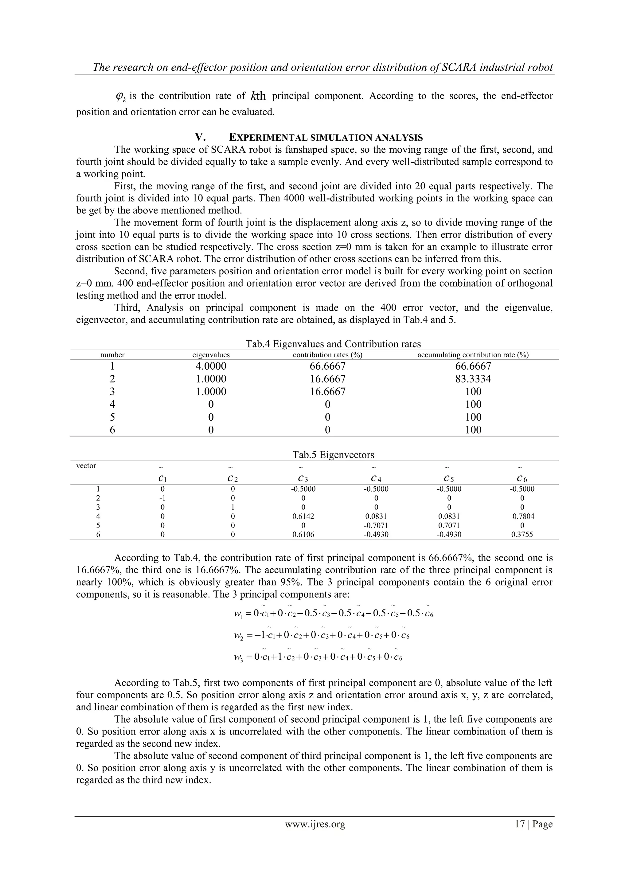
of factors contributing to the end-effector position and orientation error of SCARA robot is reduced, thus 3 new
factors are obtained. End-effector position and orientation error is depicted by a score from the principal
component analysis.
The position error from x axis and from y or z axis are pairwise uncorrelated. On the contrary, the
position error from z axis and orientation error from x y or z axis are pairwise correlated.
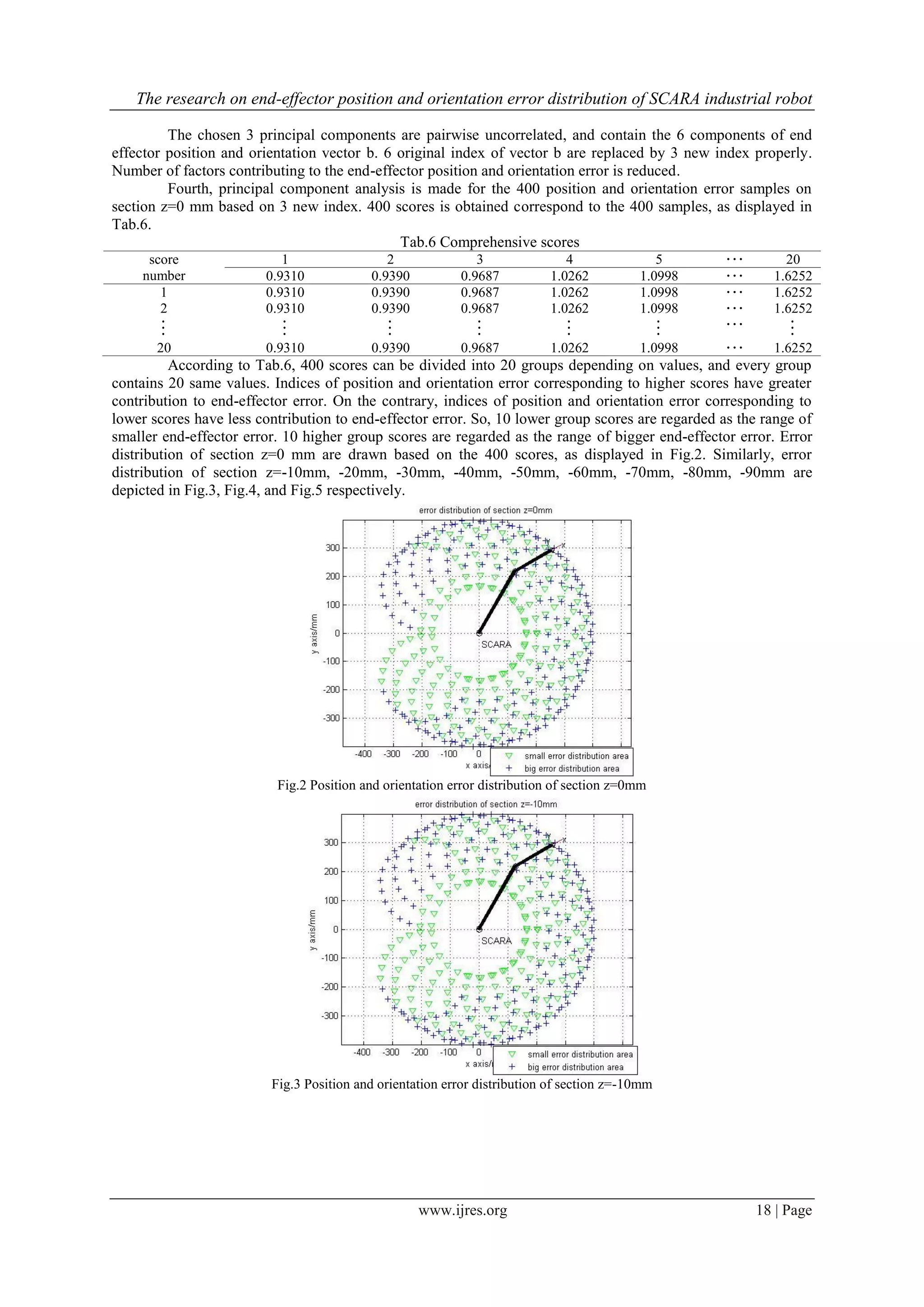
At last, several sections of error distribution are drawn based on the score. Analysis to robot end-
effector error distribuion in three dimensional working space can be made based on the sections. Position and
orientation error in the inside area of the working space is smaller than the outside area. So robot should avoid
working in the outside marginal working space. An experiment still needs to be conducted with the prototype of
SCARA robot to demonstrate the menthod to depict error distribution is reasonable.
REFERENCES
[1] Xu W L, Zhang Q X. Optimum Accuracy Design of Industrial Robot Linkage [J]. ROBOT, 1988, 10(1): 22-28.
[2] Chen M Z, Zhang Q X. Error Analyses of Industrial Robots [J]. JOURNAL OF BEIJING INSTITUTE OF AERONAUTICS AND
ASTRONAUTICS, 1984, (2): 11-22.
[3] Huang Z. The Error Analysis and Error Compensation of Robot Manipulator [J]. OPTICAL MACHINE, 1987, (1): 77-86.
[4] Hayati S, Mirmirani M. Improving the absolute positioning accuracy of robot manipulators[J]. Journal of Robotic Systems,1985,
2(4): 397-413.
[5] Burisch A, Soetebier S, Wrege J, et al. Design of a parallel hybrid micro-scara robot for high precision assembly[J]. Mechatronics
and Robotics, 2004, 4: 1370-1380.
[6] Wang W, Yun C. Orthogonal Experimental Design to Synthesize the Accuracy of Robotic Mechanism[J]. JOURNAL OF
MECHANICAL ENGINEERING, 2009, 45(11): 18-24.
[7] Wang W J, Caro S, Bennis F, et al. Multi-objective Robust Optimization Using a Postoptimality Sensitivity Analysis Technique:
Application to a Wind Turbine Design[J]. Journal of Mechanical Design, 2015, 137: 1-11
[8] Xiong Y L. Fundamentals of Robot Techniques[M]. Wuhan: HuazhongUniversity of Science and Technology Press, 1996: 55-69.
[9] Ding X L, Zhou L L, Zhou J. Pose error analysis of robot in three dimension[J]. Journal of BeijingUniversity of Aeronautics and
Astronautics, 2009, 35(2): 241-245.
[10] Ting K, Long Y. Performance Quality and Tolerance Sensitivity of Mechanisms[J]. Journal of Mechanical Design,1996, 118(1):
144-150.
[11] Caro S, Bennis F, Wenger P. Tolerance Synthesis of Mechanisms: a Robust Design Approach[J]. Journal of Mechanical
Design,2005, 127(1): 86-94.
[12] Chen K. Design and Analysis of Experiments[M]. 2th ed. Beijing: TsinghuaUniversity Press, 2005: 72-126.
[13] Cheng D X, Wang D F, Ji K S, et al. Mechanical Design Handbook[M]. 5th ed. Beijing: Chemical Industry Press, 2007: 91-154.
[14] Si S K, Sun X J. Mathematical Modeling[M]. Beijing: National Defence Industry Press, 2014: 207-216.
[15] Zhao J, Li L M, Shang H, et al. Comprehensive Evaluation of Robotic Kinematic Dexterity Performance Based on Principal
Component Analysis [J]. JOURNAL OF MECHANICAL ENGINEERING, 2014, 50(13): 9-15.](https://image.slidesharecdn.com/c36031320-150822065804-lva1-app6891/75/The-research-on-end-effector-position-and-orientation-error-distribution-of-SCARA-industrial-robot-8-2048.jpg)

The document summarizes research on modeling and analyzing the position and orientation error distribution of SCARA industrial robots. It first builds a five-parameter error model using a matrix method to relate link parameters to end-effector errors. It then uses orthogonal testing to select a small set of test points from which to derive end-effector error vectors across the workspace. Principal component analysis is applied to reduce these error vectors to a few uncorrelated factors, allowing errors to be depicted by a score. Analysis of several error distribution sections based on this score shows that errors are generally smaller at the workspace edges than inside.