SlideShare a Scribd company logo
1 of 6
Download to read offline
www.WaterProjectsOnline.com Renewable Energy 
Beckton & Crossness Thermal Hydrolysis Plants 
advanced sludge digestion facility (ESDF) 
powers up at Beckton and Crossness 
by Andre Le Roux & Andrew Bowen 
Two advanced digestion (AD) plants have been built at Crossness STW, in south-east London, and Beckton STW 
which lies to the east of the city. They were required to provide additional sludge treatment capacity and better 
operational flexibility (seasonal sludge generation and maintenance down time) for sludge management at 
the respective sites. Future increases in sludge production at the sites will be primarily due to population growth in 
the area requiring increased capacity of the STWs and once complete, the Lee Tunnel will transport greater loads 
to Beckton. Both Crossness and Beckton STWs are owned and operated by Thames Water Utilities Limited. Beckton 
STW serves a population of approximately 3.5 million and Crossness STW serves a population of approximately 2 
million. At the time of writing, Crossness and Beckton will be the joint sixth largest thermal hydrolysis plants in the 
world, each potentially treating 36,500 tonnes of dry solids per year (tDS/a) with an installed capacity of 41,975tDS/a. 
Beckton STW Raw sludge high energy mixing and storage - Courtesy of Thames Water 
Beckton STW boiler house walkways and waste heat flues - Courtesy of Thames Water 
Background 
Previously, the bulk of the existing sludge production was treated 
using the sludge powered generators (SPGs), which incinerate the 
sludge. However, these SPGs did not have the capacity to incinerate 
all of the sludge produced and relied on short-term solutions such 
as lime treatment of the sludge cake to treat the surplus sludge. 
Lime treatment of the sludge cake produces a lower quality product 
and a loss of potential renewable energy generation. 
Beckton STW Raw sludge feed pipe rack 
Courtesy of Thames Water 
Thermal hydrolysis technology pretreats sewage sludge in a two-stage 
process, combining medium-pressure boiling of sludge 
followed by a rapid decompression. This sterilizes the sludge and 
makes it more amenable to anaerobic digestion. Sterilization 
destroys pathogens in the sludge, which means it exceeds the 
stringent requirements for its subsequent use in agriculture. Since 
the first installation in Hamar, Norway in 1996, there are now over 
30 AD plants incorporating thermal hydrolysis globally. 
UK Water Projects 2014 Page 1
Torishima (Europe) Projects Limited [TEP] comprises of proven process, mechanical and electrical engineering 
teams who have over twenty-years of experience in delivering in the UK Water Sector. Dovetailing with this 
is a particular expertise in Project Management, installation, commissioning, integration and process 
optimisation. As a specialist in boiler house and associated process plant installations, we have a fully 
developed supply chain which has proved its competitiveness over recent awards and certainly offers value 
against established brands operating in this sector. 
A key area of knowledge within the business is in relation to Advanced Anaerobic Digestion [AAD] processes, 
and in particular Thermal Hydrolysis and Acid Phase/Enzymic Hydrolysis systems. 
The TEP boiler house solution benefits from its partnership with the boiler manufacturer ICI Caldaie. 
ICI Caldaie Ltd has over 50 years of experience in manufacturing high-efficiency boilers for industrial and 
commercial use. Designed to the latest European standards the company’s product range is more varied and 
comprehensive than anything else available in the market place. The sector-leading portfolio includes steam, 
thermal oil and hot water boilers as well as all boiler house ancillaries and safety systems fully compliant with 
latest legislation. Energy efficiency, reliability and environmental sustainability underpin the ICI Caldaie 
culture, with a number of innovative design features unique to its range. 
For Further information 
Tel: 01373 858 143 
Email: info@torishimaprojects.co.uk 
Web: www.torishimaprojects.co.uk 
Current Reference sites: 
• Anglian Water 
o Basildon STW 
o Cliff Quay STW 
o Colchester STW 
o Pyewipe STW 
• Thames Water 
o Crossness STW 
o Beckton STW 
• Wessex Water 
o Trowbridge STW 
• Yorkshire Water 
o Blackburn Meadows WWTW 
• Severn Trent Water 
o Worksop STW 
o Wanlip STW 
Project Feasibility // Design // Project Management // Installation 
Training // Commissioning // Integration // Service
www.WaterProjectsOnline.com Renewable Energy 
The full-scale commercial application of thermal hydrolysis of 
sewage sludge at Crossness and Beckton STWs enables the plants 
to utilise the solids portion of wastewater to produce commercially-valuable 
products directly from sewage waste; for example 
electricity and ‘class A’ biosolid fertilizers. 
Beckton & Crossness THPs 
Both the Beckton and Crossness plants incorporate thermal 
hydrolysis technology. The aim of the schemes was to allow 
refurbishment and continued use of the existing SPGs, with 
additional sludge treatment capacity provided by the new AD 
plants. The design throughput of the AD plants was 100tDS/day, 
with a peak of 115tDS/day. 
The AD plants have been designed to accommodate a wide range 
of feed compositions from 100% primary sludge to 100% secondary 
activated sludge. The biogas produced from the AD plants is used 
in the combined heat and power (CHP) engines to generate heat 
and electricity. Dewatered digested sludge is recycled to land or 
potentially to the SPGs. All sludge liquors generated during sludge 
dewatering are treated at the main sewage treatment works. 
The core process of the new AD plants is thermal hydrolysis of 
the sludge prior to digestion. This pre-treatment increases the 
digestibility of the sludge and plant throughput compared to 
conventional digesters. 
Thermal hydrolysis process 
The thermal hydrolysis process comprises two parallel THP 
streams, with each stream operating independently. Screened and 
dewatered blended sludge is fed intermittently into the pulper, 
where it is mixed and homogenised using external progressive 
cavity type pumps. Waste steam recovered from the reactors and 
flash tank is returned to the pulper to pre-heat the homogenised 
sludge. 
Homogenised, pre-heated sludge is pumped from the pulper 
to each reactor, according to the batch sequence. Sludge in the 
reactors is heated by live steam injected directly via ‘sparge’ pipes. 
The sludge is heated to raise the temperature and pressure to 165˚C 
and 6 bar respectively, and is then held under these conditions for 
30 minutes. The pressure in the reactor vessel is reduced to 2-3 bar, 
by releasing steam back to the pulper. 
The sludge is then discharged to the flash tank, using the pressure 
remaining in the reactor. The sudden de-pressurisation of the 
hydrolysed sludge causes cell walls to rupture, thereby increasing 
sludge digestibility. 
Hot, hydrolysed sludge is discharged from the flash tank and diluted 
with cold final effluent, to achieve the target %DS for feeding to 
the digesters. Each THP stream has two duty/standby progressive 
cavity pumps, which feed sludge forward to a common manifold 
for feeding 6 (No.) digesters. 
Hydrolysed sludge is then fed into 6 (No.) existing primary digesters, 
which have been refurbished and returned to service. Each digester 
has an approximate 3,500m3 working capacity, and a roof-mounted 
gas holder to provide biogas storage. 
A combination of foam traps and condensation traps were installed 
at the outlet of each gas holder, and one condensate trap was 
installed at the lowest point of the combined biogas pipeline, just 
upstream of the biogas boosters. Condensate discharges to the 
existing foul drainage system. 
Digested sludge from the digesters is pumped to post-digestion 
storage tanks and then dewatered using Bucher presses which 
produce a high dry solids cake, typically in excess of 40%, which 
Beckton STW flue stack sampling platform - Courtesy of Thames Water 
Beckton STW: Bucher final dewatering hall - Courtesy of Thames Water 
Pre-thickening centrifuges - Courtesy of Thames Water 
Beckton STW THP plant and digester with top mounted gasholders 
Courtesy of Thames Water 
UK Water Projects 2014 Page3
www.WaterProjectsOnline.com Renewable Energy 
Low Energy Consumption 
Green Technologies 
Low Lifecycle Costs 
Vacuum and Pressure Solutions for 
Water and Wastewater Applications 
Gardner Denver Ltd Claybrook Drive, Washford Industrial Estate 
Redditch, Worcestershire B98 0DS, UK 
Tel. 01527 838200 | Fax. 01527 521140 
Innovation at work 
Engineered solutions for the water treatment industry 
SCOPE OF CAPABILITIES 
 Integrated project delivery 
 Design, Fabrication, Installation and Commissioning 
 Chemical storage and dosage 
 Modular dewatering unit installation; ‘Factory Build’ concept 
 Integrated access and structural steelwork 
Richard Alan Engineering | Shaw Cross Business Park | Dewsbury | West Yorkshire | WF12 7RD 
Tel: + 44 1924 467040 | Fax: + 44 1924 454377 | email: watertreatment@richardalan.co.uk, 
www.richardalanwater.co.uk 
UK Water Projects 2014 Page 4
www.WaterProjectsOnline.com Renewable Energy 
reduces volumes for storage, transport and recycling. Thames 
Water is the first UK water company to invest in this technology. 
Dewatered cake is subsequently stored in a fully enclosed cake 
storage area within the sludge cake building. All centrate and 
filtrate generated is treated at the main sewage treatment works. 
Biogas is primarily used to supply 3 (No.) CHP engines (duty/assist/ 
assist) to maximise green energy generation. Excess biogas is flared 
via the waste gas burner. 
There are 2 (No.) composite steam boilers which are linked to the 
CHP engines by exhaust gas flues in order to recover heat from the 
hot engine gases, thereby reducing the amount of supplementary 
fuel (natural gas) required. The gas-fired side of each boiler is 
capable of generating up to 6,000kg/h of steam. 
Each boiler has two separate waste heat sections, with one boiler 
linked to two CHPs and the other to a single CHP. Each waste heat 
recovery section is sized to generate up to 1,000kg/h of steam. 
The biogas treatment and utilisation incorporates the following 
equipment: 
Biogas Boosters: All biogas produced is stored in roof-mounted 
gas holders. Biogas from the digesters is boosted from 8mbar to 
150mbar, via 3 (No.) duty/assist/standby biogas boosters. 
Biogas Dehumidifier: Biogas supplied to the CHPs and boilers is 
dehumidified, to reduce the relative humidity of the biogas to 55% 
at 10°C. The dehumidification process involves cooling the biogas 
with a heat exchanger, with water as the cooling medium, and re-heating 
by a gas-gas heat exchanger, using the heat from the inlet 
raw biogas. Accumulated condensate is discharged to a collection 
tank and transferred to the return liquors pumping station. 
Siloxane Removal: Due to risk of siloxanes in the biogas, a series of 
siloxane carbon filters have been installed. The system will operate 
in a primary/ secondary arrangement with removal of each carbon 
cartridge for off-site carbon replacement. 
CHP Plant: 3 (No.) Edina packaged CHP units with MWM engines 
have been installed at each AD plant. Each containerised unit 
comprises the following: 
• Gas engine. 
• Alternator and all associated ancillaries. 
• Exhaust silencers. 
• Ground mounted waste heat dump radiator. 
• A low-temperature hot water heat recovery circulation 
system. 
• Control room. 
• Compartment ventilation system. 
• Separate dirty/clean oil storage tank system. 
These engines are fuelled by the biogas generated in the digesters 
and each have the capacity to generate 2MWe. Each unit has an 
overall efficiency of 84.2% at 100% load, with 42.9% as electrical 
energy generation and 41.3% as recoverable thermal energy. 
The CHP generators produce electricity at 11kV at Crossness and 
6.6kV at Beckton, feeding into a new THP HV board. The new board 
is connected to the existing site HV switch gear through a dual-feed 
arrangement. 
The CHP units’ operation is controlled by an automatic generator 
management system (AGMS), which controls the operating 
load and number of operating CHPs according to the site HV 
configuration and the quantity of biogas generated. The AGMS will 
also control the HV breaker set-up, based on information from the 
site power management system. 
Beckton STW: Bucher units for final sludge dewatering - Courtesy of Thames Water 
UK Water Projects 2014 Page 5
www.WaterProjectsOnline.com Renewable Energy 
During average design plant operation, sufficient biogas will be 
produced to generate 4.2MW of electricity. The number of CHPs 
in operation and the power output of each engine is therefore 
determined by the average biogas level in the gas holders. Each 
self-contained CHP unit is supplied with its own cooling circuit: 
intercooler circuit and engine cooler system. 
Each of these systems is connected to a heat dump radiator, which 
is sized to be able to reject the maximum amount of heat from the 
intercooler water circuit (if there is no low-grade heat recovery). 
High-grade heat from the CHPs exhaust is recovered in the waste 
heat section of the steam boilers to generate steam for the thermal 
Hydrolysis plants. 
Any additional steam demand by the THP is met by burning natural 
gas (as supplementary fuel) in the steam boilers. Low-grade heat 
from the CHPs cooling system is recovered to pre-heat the boiler 
feed water from 10°C to 70°C. All condensate recovered from the 
steam header and pipelines – via the steam traps and condensate 
drains – returns to the boiler water feed tank. 
Site electrical demand 
The site distribution network operator is UK Power Networks. The 
AD plants’ total site electricity demand includes all the AD plant 
equipment operating at design load and design sludge feed 
composition. The peak electricity demand is associated with peak 
loads through the plant. 
The site electrical demand only includes the ESDF and excludes 
the rest of the sewage treatment works. Power generated from the 
CHPs is for use on the Crossness and Beckton STWs and any excess 
will be exported. Electricity to the existing site is metered via two 
OFGEM certified power meters. 
THP Site Electrical Demand 
Crossness 
Total installed capacity of the Generating Station 
(TIC) 
6,000kWe 
Declared Net Capacity of the Generating Station 
(DNC) 
5,794kWe 
Average Parasitic Load of the Generating Station 
• Biogas Boosters 
• Biogas Dehumidifier 
• CHP auxiliaries 
• TOTAL 
33kWe 
11kWe 
162kWe 
206kWe 
Total Average AD Plant Electrical Demand 2,119kWe 
Total Maximum AD Plant Electrical Demand 2,399kWe 
THP Site Electrical Demand 
Beckton 
Total installed capacity of the Generating Station 
(TIC) 
6,000kWe 
Declared Net Capacity of the Generating Station 
(DNC) 
5,794kWe 
Average Parasitic Load of the Generating Station 
• Biogas Boosters 
• Biogas Dehumidifier 
• CHP auxiliaries 
• TOTAL 
33kWe 
11kWe 
162kWe 
206kWe 
Total Average AD Plant Electrical Demand 2,162kWe 
Total Maximum AD Plant Electrical Demand 2,450kWe 
Undertakings 
The work undertaken to construct and install the THP plants at 
Crossness and Beckton was carried out by Tamesis, a Joint Venture 
between Laing O’Rourke and Imtech. Other contractors on the 
schemes included: 
Key Participants 
Thermal Hydrolysis Plant Cambi 
CHPs Edina 
Boiler house Torishima 
Centrifuges GEA 
Final thickening Bucher 
Poly plants Richard Alan 
Thickened sludge storage Spirac 
Gas holders and GCS tanks Kirk Environmental 
Sludge coolers HRS 
Mechanical installation Merit Merrell 
JK Fabrication 
Steelworks ECS 
Billingtons 
Cladding FK Group 
MCCs GPS 
HV panels HSSL 
HV installation IUS 
LV installation (Crossness) Imtech Engineering Services 
Central 
LV installation (Beckton) Bridges 
Systems integration & AGMs Capula 
Civil construction at Crossness started in October 2012, with 
the mechanical installation commencing in April 2013. Dry 
commissioning started in February 2014 and wet commissioning 
started in April 2014. The THP plant was first fired in May 2014, with 
electricity production planned for August 2014. 
At Beckton, the civil construction started October 2012, with 
the mechanical installation commencing in July 2013. Dry 
commissioning started in July 2014 and wet commissioning started 
in August 2014. The THP plant is planned for start-up in September 
2014, with electricity production planned for October 2014. 
The Editor & Publishers thank Andre Le Roux, Technical Manager 
with Imtech, and Andrew Bowen, THP Design Project Manager 
with Tamesis, for providing the above article for publication. 
The authors wish to thank Thames Water for its support, as well as 
all the companies and their employees who have contributed to 
the successful delivery of this project. 
Boiler flues - Courtesy of Thames Water 
UK Water Projects 2014 Page 6

More Related Content

Viewers also liked

C mo elegir_una_lectura_para_tu_hijo_de_6_a_11_a_os
C mo elegir_una_lectura_para_tu_hijo_de_6_a_11_a_osC mo elegir_una_lectura_para_tu_hijo_de_6_a_11_a_os
C mo elegir_una_lectura_para_tu_hijo_de_6_a_11_a_osMaricarmenmartinezgil
 
El entorno de la empresa
El entorno de la empresaEl entorno de la empresa
El entorno de la empresalidytazo
 
A los trabajadores del tren
A los trabajadores del trenA los trabajadores del tren
A los trabajadores del trencreacionesdanae
 
Historia de abraham
Historia de abrahamHistoria de abraham
Historia de abrahamMiguel-1
 
Hawaii Swnt Ao
Hawaii Swnt AoHawaii Swnt Ao
Hawaii Swnt AoAntonini
 
TMTC_Process Improvement
TMTC_Process ImprovementTMTC_Process Improvement
TMTC_Process ImprovementNandita mitra
 
Tics en la educacion
Tics en la educacionTics en la educacion
Tics en la educacioneucas75
 
Proyecto final
Proyecto finalProyecto final
Proyecto finalJosh7129
 
Estudio comparativo entre finlandia y ecuador
Estudio comparativo entre  finlandia y ecuadorEstudio comparativo entre  finlandia y ecuador
Estudio comparativo entre finlandia y ecuadorJuliovega64
 
Comunicado Carlos Joaquín
Comunicado Carlos JoaquínComunicado Carlos Joaquín
Comunicado Carlos JoaquínHaide Serrano
 
Computing Loops
Computing LoopsComputing Loops
Computing LoopsAntonini
 

Viewers also liked (20)

Saludo (las) (1)
Saludo (las) (1)Saludo (las) (1)
Saludo (las) (1)
 
C mo elegir_una_lectura_para_tu_hijo_de_6_a_11_a_os
C mo elegir_una_lectura_para_tu_hijo_de_6_a_11_a_osC mo elegir_una_lectura_para_tu_hijo_de_6_a_11_a_os
C mo elegir_una_lectura_para_tu_hijo_de_6_a_11_a_os
 
El entorno de la empresa
El entorno de la empresaEl entorno de la empresa
El entorno de la empresa
 
Anorexia...
Anorexia...Anorexia...
Anorexia...
 
A los trabajadores del tren
A los trabajadores del trenA los trabajadores del tren
A los trabajadores del tren
 
Pátio carioca
Pátio cariocaPátio carioca
Pátio carioca
 
Ese es dios
Ese es diosEse es dios
Ese es dios
 
Historia de abraham
Historia de abrahamHistoria de abraham
Historia de abraham
 
Hawaii Swnt Ao
Hawaii Swnt AoHawaii Swnt Ao
Hawaii Swnt Ao
 
TMTC_Process Improvement
TMTC_Process ImprovementTMTC_Process Improvement
TMTC_Process Improvement
 
Tics en la educacion
Tics en la educacionTics en la educacion
Tics en la educacion
 
Proyecto final
Proyecto finalProyecto final
Proyecto final
 
Estudio comparativo entre finlandia y ecuador
Estudio comparativo entre  finlandia y ecuadorEstudio comparativo entre  finlandia y ecuador
Estudio comparativo entre finlandia y ecuador
 
Ing. patricio hoy
Ing. patricio hoyIng. patricio hoy
Ing. patricio hoy
 
Comunicado Carlos Joaquín
Comunicado Carlos JoaquínComunicado Carlos Joaquín
Comunicado Carlos Joaquín
 
Tutorial 2 plagio
Tutorial 2 plagioTutorial 2 plagio
Tutorial 2 plagio
 
Colores (1)
Colores (1)Colores (1)
Colores (1)
 
COMPARTIENDO EL QUIJOTE. SEGUNDA JORNADA
COMPARTIENDO EL QUIJOTE. SEGUNDA JORNADACOMPARTIENDO EL QUIJOTE. SEGUNDA JORNADA
COMPARTIENDO EL QUIJOTE. SEGUNDA JORNADA
 
Visita guiada al castillo día 12 de Julio
Visita guiada al castillo día 12 de JulioVisita guiada al castillo día 12 de Julio
Visita guiada al castillo día 12 de Julio
 
Computing Loops
Computing LoopsComputing Loops
Computing Loops
 

Similar to Thames_Beckton_Crossness_THPs_2014

AWA Water e-journal article: Energy and Nutrient Factory at Amersfoort WWTP i...
AWA Water e-journal article: Energy and Nutrient Factory at Amersfoort WWTP i...AWA Water e-journal article: Energy and Nutrient Factory at Amersfoort WWTP i...
AWA Water e-journal article: Energy and Nutrient Factory at Amersfoort WWTP i...Luc Kox
 
Degremont industry power brochure
Degremont industry power brochureDegremont industry power brochure
Degremont industry power brochureRick Nabett
 
Severn_Trent_Wanlip_Sludge_2014
Severn_Trent_Wanlip_Sludge_2014Severn_Trent_Wanlip_Sludge_2014
Severn_Trent_Wanlip_Sludge_2014Iain McGregor
 
NI_Water_Dunmurry_2012
NI_Water_Dunmurry_2012NI_Water_Dunmurry_2012
NI_Water_Dunmurry_2012Mike Vernon
 
Thames Perry Oaks-Iver South 2005
Thames Perry Oaks-Iver South 2005Thames Perry Oaks-Iver South 2005
Thames Perry Oaks-Iver South 2005Robert Sharpe
 
Leading Water Utilities Reducing Water-Energy Nexus Pressures
Leading Water Utilities Reducing Water-Energy Nexus PressuresLeading Water Utilities Reducing Water-Energy Nexus Pressures
Leading Water Utilities Reducing Water-Energy Nexus PressuresRobert Brears
 
UU_Davyhulme_Modernisation_2016
UU_Davyhulme_Modernisation_2016UU_Davyhulme_Modernisation_2016
UU_Davyhulme_Modernisation_2016Charlie Bell
 
dow-ksb-the-company-that-keeps-it-moving-data
dow-ksb-the-company-that-keeps-it-moving-datadow-ksb-the-company-that-keeps-it-moving-data
dow-ksb-the-company-that-keeps-it-moving-dataSyed Muhammad Fahad
 
PIA Magazine May - June 2014 (lift-out)
PIA Magazine May - June 2014 (lift-out)PIA Magazine May - June 2014 (lift-out)
PIA Magazine May - June 2014 (lift-out)Matt Kirkbride
 
Rosslyn Brewery SAIMechEng Projects&Systems Award 1987
Rosslyn Brewery SAIMechEng Projects&Systems Award 1987 Rosslyn Brewery SAIMechEng Projects&Systems Award 1987
Rosslyn Brewery SAIMechEng Projects&Systems Award 1987 John Cluett
 
Environmental presentation from malthouse engineering
Environmental presentation from malthouse engineeringEnvironmental presentation from malthouse engineering
Environmental presentation from malthouse engineeringMalthouse Engineering Ltd.
 
New technology for desalination
New technology for desalinationNew technology for desalination
New technology for desalinationDainik Patel
 
tianjin by hagay shemer[1]
tianjin by hagay shemer[1]tianjin by hagay shemer[1]
tianjin by hagay shemer[1]hagay shemer
 
Operation of Solar and Waste-heat Powered Adsorption Desalination
Operation of Solar and Waste-heat Powered Adsorption DesalinationOperation of Solar and Waste-heat Powered Adsorption Desalination
Operation of Solar and Waste-heat Powered Adsorption Desalinationiskandaruz
 
Report Guddu Power Plant
Report Guddu Power PlantReport Guddu Power Plant
Report Guddu Power PlantMuhammad Ahmed
 
Durgapur Projects Limited
Durgapur Projects LimitedDurgapur Projects Limited
Durgapur Projects LimitedSupriya Gorai
 
Presentation of thermal_power_plant
Presentation of thermal_power_plantPresentation of thermal_power_plant
Presentation of thermal_power_plantprakash2704
 
Internship Report of Jamshoro Power Company Limited (JPCL)
Internship Report of Jamshoro Power Company Limited (JPCL)Internship Report of Jamshoro Power Company Limited (JPCL)
Internship Report of Jamshoro Power Company Limited (JPCL)Aamir Ali Seelro
 

Similar to Thames_Beckton_Crossness_THPs_2014 (20)

AWA Water e-journal article: Energy and Nutrient Factory at Amersfoort WWTP i...
AWA Water e-journal article: Energy and Nutrient Factory at Amersfoort WWTP i...AWA Water e-journal article: Energy and Nutrient Factory at Amersfoort WWTP i...
AWA Water e-journal article: Energy and Nutrient Factory at Amersfoort WWTP i...
 
Degremont industry power brochure
Degremont industry power brochureDegremont industry power brochure
Degremont industry power brochure
 
Severn_Trent_Wanlip_Sludge_2014
Severn_Trent_Wanlip_Sludge_2014Severn_Trent_Wanlip_Sludge_2014
Severn_Trent_Wanlip_Sludge_2014
 
NI_Water_Dunmurry_2012
NI_Water_Dunmurry_2012NI_Water_Dunmurry_2012
NI_Water_Dunmurry_2012
 
Thames Perry Oaks-Iver South 2005
Thames Perry Oaks-Iver South 2005Thames Perry Oaks-Iver South 2005
Thames Perry Oaks-Iver South 2005
 
Leading Water Utilities Reducing Water-Energy Nexus Pressures
Leading Water Utilities Reducing Water-Energy Nexus PressuresLeading Water Utilities Reducing Water-Energy Nexus Pressures
Leading Water Utilities Reducing Water-Energy Nexus Pressures
 
UU_Davyhulme_Modernisation_2016
UU_Davyhulme_Modernisation_2016UU_Davyhulme_Modernisation_2016
UU_Davyhulme_Modernisation_2016
 
dow-ksb-the-company-that-keeps-it-moving-data
dow-ksb-the-company-that-keeps-it-moving-datadow-ksb-the-company-that-keeps-it-moving-data
dow-ksb-the-company-that-keeps-it-moving-data
 
PIA Magazine May - June 2014 (lift-out)
PIA Magazine May - June 2014 (lift-out)PIA Magazine May - June 2014 (lift-out)
PIA Magazine May - June 2014 (lift-out)
 
Boiler Economiser .pdf
Boiler Economiser .pdfBoiler Economiser .pdf
Boiler Economiser .pdf
 
Rosslyn Brewery SAIMechEng Projects&Systems Award 1987
Rosslyn Brewery SAIMechEng Projects&Systems Award 1987 Rosslyn Brewery SAIMechEng Projects&Systems Award 1987
Rosslyn Brewery SAIMechEng Projects&Systems Award 1987
 
Environmental presentation from malthouse engineering
Environmental presentation from malthouse engineeringEnvironmental presentation from malthouse engineering
Environmental presentation from malthouse engineering
 
New technology for desalination
New technology for desalinationNew technology for desalination
New technology for desalination
 
tianjin by hagay shemer[1]
tianjin by hagay shemer[1]tianjin by hagay shemer[1]
tianjin by hagay shemer[1]
 
Operation of Solar and Waste-heat Powered Adsorption Desalination
Operation of Solar and Waste-heat Powered Adsorption DesalinationOperation of Solar and Waste-heat Powered Adsorption Desalination
Operation of Solar and Waste-heat Powered Adsorption Desalination
 
Report Guddu Power Plant
Report Guddu Power PlantReport Guddu Power Plant
Report Guddu Power Plant
 
Durgapur Projects Limited
Durgapur Projects LimitedDurgapur Projects Limited
Durgapur Projects Limited
 
Heat exchangers
Heat exchangersHeat exchangers
Heat exchangers
 
Presentation of thermal_power_plant
Presentation of thermal_power_plantPresentation of thermal_power_plant
Presentation of thermal_power_plant
 
Internship Report of Jamshoro Power Company Limited (JPCL)
Internship Report of Jamshoro Power Company Limited (JPCL)Internship Report of Jamshoro Power Company Limited (JPCL)
Internship Report of Jamshoro Power Company Limited (JPCL)
 

Thames_Beckton_Crossness_THPs_2014

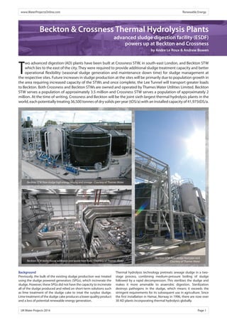
  • 1. www.WaterProjectsOnline.com Renewable Energy Beckton & Crossness Thermal Hydrolysis Plants advanced sludge digestion facility (ESDF) powers up at Beckton and Crossness by Andre Le Roux & Andrew Bowen Two advanced digestion (AD) plants have been built at Crossness STW, in south-east London, and Beckton STW which lies to the east of the city. They were required to provide additional sludge treatment capacity and better operational flexibility (seasonal sludge generation and maintenance down time) for sludge management at the respective sites. Future increases in sludge production at the sites will be primarily due to population growth in the area requiring increased capacity of the STWs and once complete, the Lee Tunnel will transport greater loads to Beckton. Both Crossness and Beckton STWs are owned and operated by Thames Water Utilities Limited. Beckton STW serves a population of approximately 3.5 million and Crossness STW serves a population of approximately 2 million. At the time of writing, Crossness and Beckton will be the joint sixth largest thermal hydrolysis plants in the world, each potentially treating 36,500 tonnes of dry solids per year (tDS/a) with an installed capacity of 41,975tDS/a. Beckton STW Raw sludge high energy mixing and storage - Courtesy of Thames Water Beckton STW boiler house walkways and waste heat flues - Courtesy of Thames Water Background Previously, the bulk of the existing sludge production was treated using the sludge powered generators (SPGs), which incinerate the sludge. However, these SPGs did not have the capacity to incinerate all of the sludge produced and relied on short-term solutions such as lime treatment of the sludge cake to treat the surplus sludge. Lime treatment of the sludge cake produces a lower quality product and a loss of potential renewable energy generation. Beckton STW Raw sludge feed pipe rack Courtesy of Thames Water Thermal hydrolysis technology pretreats sewage sludge in a two-stage process, combining medium-pressure boiling of sludge followed by a rapid decompression. This sterilizes the sludge and makes it more amenable to anaerobic digestion. Sterilization destroys pathogens in the sludge, which means it exceeds the stringent requirements for its subsequent use in agriculture. Since the first installation in Hamar, Norway in 1996, there are now over 30 AD plants incorporating thermal hydrolysis globally. UK Water Projects 2014 Page 1
  • 2. Torishima (Europe) Projects Limited [TEP] comprises of proven process, mechanical and electrical engineering teams who have over twenty-years of experience in delivering in the UK Water Sector. Dovetailing with this is a particular expertise in Project Management, installation, commissioning, integration and process optimisation. As a specialist in boiler house and associated process plant installations, we have a fully developed supply chain which has proved its competitiveness over recent awards and certainly offers value against established brands operating in this sector. A key area of knowledge within the business is in relation to Advanced Anaerobic Digestion [AAD] processes, and in particular Thermal Hydrolysis and Acid Phase/Enzymic Hydrolysis systems. The TEP boiler house solution benefits from its partnership with the boiler manufacturer ICI Caldaie. ICI Caldaie Ltd has over 50 years of experience in manufacturing high-efficiency boilers for industrial and commercial use. Designed to the latest European standards the company’s product range is more varied and comprehensive than anything else available in the market place. The sector-leading portfolio includes steam, thermal oil and hot water boilers as well as all boiler house ancillaries and safety systems fully compliant with latest legislation. Energy efficiency, reliability and environmental sustainability underpin the ICI Caldaie culture, with a number of innovative design features unique to its range. For Further information Tel: 01373 858 143 Email: info@torishimaprojects.co.uk Web: www.torishimaprojects.co.uk Current Reference sites: • Anglian Water o Basildon STW o Cliff Quay STW o Colchester STW o Pyewipe STW • Thames Water o Crossness STW o Beckton STW • Wessex Water o Trowbridge STW • Yorkshire Water o Blackburn Meadows WWTW • Severn Trent Water o Worksop STW o Wanlip STW Project Feasibility // Design // Project Management // Installation Training // Commissioning // Integration // Service
  • 3. www.WaterProjectsOnline.com Renewable Energy The full-scale commercial application of thermal hydrolysis of sewage sludge at Crossness and Beckton STWs enables the plants to utilise the solids portion of wastewater to produce commercially-valuable products directly from sewage waste; for example electricity and ‘class A’ biosolid fertilizers. Beckton & Crossness THPs Both the Beckton and Crossness plants incorporate thermal hydrolysis technology. The aim of the schemes was to allow refurbishment and continued use of the existing SPGs, with additional sludge treatment capacity provided by the new AD plants. The design throughput of the AD plants was 100tDS/day, with a peak of 115tDS/day. The AD plants have been designed to accommodate a wide range of feed compositions from 100% primary sludge to 100% secondary activated sludge. The biogas produced from the AD plants is used in the combined heat and power (CHP) engines to generate heat and electricity. Dewatered digested sludge is recycled to land or potentially to the SPGs. All sludge liquors generated during sludge dewatering are treated at the main sewage treatment works. The core process of the new AD plants is thermal hydrolysis of the sludge prior to digestion. This pre-treatment increases the digestibility of the sludge and plant throughput compared to conventional digesters. Thermal hydrolysis process The thermal hydrolysis process comprises two parallel THP streams, with each stream operating independently. Screened and dewatered blended sludge is fed intermittently into the pulper, where it is mixed and homogenised using external progressive cavity type pumps. Waste steam recovered from the reactors and flash tank is returned to the pulper to pre-heat the homogenised sludge. Homogenised, pre-heated sludge is pumped from the pulper to each reactor, according to the batch sequence. Sludge in the reactors is heated by live steam injected directly via ‘sparge’ pipes. The sludge is heated to raise the temperature and pressure to 165˚C and 6 bar respectively, and is then held under these conditions for 30 minutes. The pressure in the reactor vessel is reduced to 2-3 bar, by releasing steam back to the pulper. The sludge is then discharged to the flash tank, using the pressure remaining in the reactor. The sudden de-pressurisation of the hydrolysed sludge causes cell walls to rupture, thereby increasing sludge digestibility. Hot, hydrolysed sludge is discharged from the flash tank and diluted with cold final effluent, to achieve the target %DS for feeding to the digesters. Each THP stream has two duty/standby progressive cavity pumps, which feed sludge forward to a common manifold for feeding 6 (No.) digesters. Hydrolysed sludge is then fed into 6 (No.) existing primary digesters, which have been refurbished and returned to service. Each digester has an approximate 3,500m3 working capacity, and a roof-mounted gas holder to provide biogas storage. A combination of foam traps and condensation traps were installed at the outlet of each gas holder, and one condensate trap was installed at the lowest point of the combined biogas pipeline, just upstream of the biogas boosters. Condensate discharges to the existing foul drainage system. Digested sludge from the digesters is pumped to post-digestion storage tanks and then dewatered using Bucher presses which produce a high dry solids cake, typically in excess of 40%, which Beckton STW flue stack sampling platform - Courtesy of Thames Water Beckton STW: Bucher final dewatering hall - Courtesy of Thames Water Pre-thickening centrifuges - Courtesy of Thames Water Beckton STW THP plant and digester with top mounted gasholders Courtesy of Thames Water UK Water Projects 2014 Page3
  • 4. www.WaterProjectsOnline.com Renewable Energy Low Energy Consumption Green Technologies Low Lifecycle Costs Vacuum and Pressure Solutions for Water and Wastewater Applications Gardner Denver Ltd Claybrook Drive, Washford Industrial Estate Redditch, Worcestershire B98 0DS, UK Tel. 01527 838200 | Fax. 01527 521140 Innovation at work Engineered solutions for the water treatment industry SCOPE OF CAPABILITIES  Integrated project delivery  Design, Fabrication, Installation and Commissioning  Chemical storage and dosage  Modular dewatering unit installation; ‘Factory Build’ concept  Integrated access and structural steelwork Richard Alan Engineering | Shaw Cross Business Park | Dewsbury | West Yorkshire | WF12 7RD Tel: + 44 1924 467040 | Fax: + 44 1924 454377 | email: watertreatment@richardalan.co.uk, www.richardalanwater.co.uk UK Water Projects 2014 Page 4
  • 5. www.WaterProjectsOnline.com Renewable Energy reduces volumes for storage, transport and recycling. Thames Water is the first UK water company to invest in this technology. Dewatered cake is subsequently stored in a fully enclosed cake storage area within the sludge cake building. All centrate and filtrate generated is treated at the main sewage treatment works. Biogas is primarily used to supply 3 (No.) CHP engines (duty/assist/ assist) to maximise green energy generation. Excess biogas is flared via the waste gas burner. There are 2 (No.) composite steam boilers which are linked to the CHP engines by exhaust gas flues in order to recover heat from the hot engine gases, thereby reducing the amount of supplementary fuel (natural gas) required. The gas-fired side of each boiler is capable of generating up to 6,000kg/h of steam. Each boiler has two separate waste heat sections, with one boiler linked to two CHPs and the other to a single CHP. Each waste heat recovery section is sized to generate up to 1,000kg/h of steam. The biogas treatment and utilisation incorporates the following equipment: Biogas Boosters: All biogas produced is stored in roof-mounted gas holders. Biogas from the digesters is boosted from 8mbar to 150mbar, via 3 (No.) duty/assist/standby biogas boosters. Biogas Dehumidifier: Biogas supplied to the CHPs and boilers is dehumidified, to reduce the relative humidity of the biogas to 55% at 10°C. The dehumidification process involves cooling the biogas with a heat exchanger, with water as the cooling medium, and re-heating by a gas-gas heat exchanger, using the heat from the inlet raw biogas. Accumulated condensate is discharged to a collection tank and transferred to the return liquors pumping station. Siloxane Removal: Due to risk of siloxanes in the biogas, a series of siloxane carbon filters have been installed. The system will operate in a primary/ secondary arrangement with removal of each carbon cartridge for off-site carbon replacement. CHP Plant: 3 (No.) Edina packaged CHP units with MWM engines have been installed at each AD plant. Each containerised unit comprises the following: • Gas engine. • Alternator and all associated ancillaries. • Exhaust silencers. • Ground mounted waste heat dump radiator. • A low-temperature hot water heat recovery circulation system. • Control room. • Compartment ventilation system. • Separate dirty/clean oil storage tank system. These engines are fuelled by the biogas generated in the digesters and each have the capacity to generate 2MWe. Each unit has an overall efficiency of 84.2% at 100% load, with 42.9% as electrical energy generation and 41.3% as recoverable thermal energy. The CHP generators produce electricity at 11kV at Crossness and 6.6kV at Beckton, feeding into a new THP HV board. The new board is connected to the existing site HV switch gear through a dual-feed arrangement. The CHP units’ operation is controlled by an automatic generator management system (AGMS), which controls the operating load and number of operating CHPs according to the site HV configuration and the quantity of biogas generated. The AGMS will also control the HV breaker set-up, based on information from the site power management system. Beckton STW: Bucher units for final sludge dewatering - Courtesy of Thames Water UK Water Projects 2014 Page 5
  • 6. www.WaterProjectsOnline.com Renewable Energy During average design plant operation, sufficient biogas will be produced to generate 4.2MW of electricity. The number of CHPs in operation and the power output of each engine is therefore determined by the average biogas level in the gas holders. Each self-contained CHP unit is supplied with its own cooling circuit: intercooler circuit and engine cooler system. Each of these systems is connected to a heat dump radiator, which is sized to be able to reject the maximum amount of heat from the intercooler water circuit (if there is no low-grade heat recovery). High-grade heat from the CHPs exhaust is recovered in the waste heat section of the steam boilers to generate steam for the thermal Hydrolysis plants. Any additional steam demand by the THP is met by burning natural gas (as supplementary fuel) in the steam boilers. Low-grade heat from the CHPs cooling system is recovered to pre-heat the boiler feed water from 10°C to 70°C. All condensate recovered from the steam header and pipelines – via the steam traps and condensate drains – returns to the boiler water feed tank. Site electrical demand The site distribution network operator is UK Power Networks. The AD plants’ total site electricity demand includes all the AD plant equipment operating at design load and design sludge feed composition. The peak electricity demand is associated with peak loads through the plant. The site electrical demand only includes the ESDF and excludes the rest of the sewage treatment works. Power generated from the CHPs is for use on the Crossness and Beckton STWs and any excess will be exported. Electricity to the existing site is metered via two OFGEM certified power meters. THP Site Electrical Demand Crossness Total installed capacity of the Generating Station (TIC) 6,000kWe Declared Net Capacity of the Generating Station (DNC) 5,794kWe Average Parasitic Load of the Generating Station • Biogas Boosters • Biogas Dehumidifier • CHP auxiliaries • TOTAL 33kWe 11kWe 162kWe 206kWe Total Average AD Plant Electrical Demand 2,119kWe Total Maximum AD Plant Electrical Demand 2,399kWe THP Site Electrical Demand Beckton Total installed capacity of the Generating Station (TIC) 6,000kWe Declared Net Capacity of the Generating Station (DNC) 5,794kWe Average Parasitic Load of the Generating Station • Biogas Boosters • Biogas Dehumidifier • CHP auxiliaries • TOTAL 33kWe 11kWe 162kWe 206kWe Total Average AD Plant Electrical Demand 2,162kWe Total Maximum AD Plant Electrical Demand 2,450kWe Undertakings The work undertaken to construct and install the THP plants at Crossness and Beckton was carried out by Tamesis, a Joint Venture between Laing O’Rourke and Imtech. Other contractors on the schemes included: Key Participants Thermal Hydrolysis Plant Cambi CHPs Edina Boiler house Torishima Centrifuges GEA Final thickening Bucher Poly plants Richard Alan Thickened sludge storage Spirac Gas holders and GCS tanks Kirk Environmental Sludge coolers HRS Mechanical installation Merit Merrell JK Fabrication Steelworks ECS Billingtons Cladding FK Group MCCs GPS HV panels HSSL HV installation IUS LV installation (Crossness) Imtech Engineering Services Central LV installation (Beckton) Bridges Systems integration & AGMs Capula Civil construction at Crossness started in October 2012, with the mechanical installation commencing in April 2013. Dry commissioning started in February 2014 and wet commissioning started in April 2014. The THP plant was first fired in May 2014, with electricity production planned for August 2014. At Beckton, the civil construction started October 2012, with the mechanical installation commencing in July 2013. Dry commissioning started in July 2014 and wet commissioning started in August 2014. The THP plant is planned for start-up in September 2014, with electricity production planned for October 2014. The Editor & Publishers thank Andre Le Roux, Technical Manager with Imtech, and Andrew Bowen, THP Design Project Manager with Tamesis, for providing the above article for publication. The authors wish to thank Thames Water for its support, as well as all the companies and their employees who have contributed to the successful delivery of this project. Boiler flues - Courtesy of Thames Water UK Water Projects 2014 Page 6