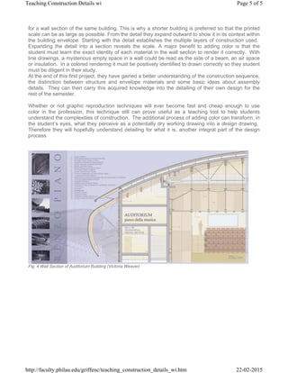
Teaching Construction Details with Color
Craig Griffen
Philadelphia University
Color in Technical Drawing
A technical drawing mainly differs from a design drawing in the fact that it conveys greater detail of
the physical relationships between various materials and their methods of assembly.
Communicating this precise information often results, by necessity, in rote working drawings that can
be understood by the contractors who must build the design. Traditionally, technical drawings have
been ‘black and white’ line drawings because of the necessity for low-cost blueprint reproductions.
But the main purpose of any architectural drawing, whether design or technical, is to communicate
the design intentions to the reader. Therefore, new digital methods of graphic reproduction create a
new potential for technical drawings that can better communicate these intentions, especially as a
teaching tool in academia.
The two-dimensional nature of working drawings is efficient in specifying exact dimensional
relationships between materials but it flatness can make it difficult to distinguish what is drawn in
section versus what is drawn in elevation. Students, who typically have little experience with working
drawings, often have a hard time reading them. A variety of line weights can help create spatial
depth but is still limiting in a black and white format. Computer drafting can make line weight even
harder to understand as thickness is replaced by color on the screen. While a standard set of colors
that tries to match heavier lines to advancing colors and lighter lines to receding colors can help
imply thickness, students read colors differently. Some see red as an advancing color and some see
it as receding. Therefore they often create their own line weight-to-color assignments that make it
even more difficult to read their work. Plotting the drawings is the only way to test the legibility and
students are reluctant to stop and take the time to print. They think they understand what they are
drawing even if others don’t. This reluctance to print presents problems since colored lines on a
black monitor screen are the reverse image of the final drawing with “black” lines on white paper. So
a paradox of drawing on the computer is that while it has the potential for amazing graphics in a short
period of time, the interface between screen image and paper image is more disconnected than
drawing by hand. It takes practice, imagination and a lot of trial and error plotting to be able to
visualize the final drawing from a screen image.
Page 1 of 5Teaching Construction Details wi
22-02-2015http://faculty.philau.edu/griffenc/teaching_construction_details_wi.htm
Fig. 1 Wall Section of Padre Pio Church (Ben Liddick)
In terms of rendering patterns in black and white, material designations and symbols help distinguish
between materials cut in section or shown in elevation as well as identify the materials themselves.
However not all symbols are universally accepted and while some help distinguish a material as
different from what is next to it, they don’t always specifically identify it. (i.e. glass, metal panel and
even an open void can look the same in elevation) New methods of color reproduction can be helpful
to more clearly identify materials. The computer provides us with the ability to quickly add tone, color,
texture, shading, etc. to explain and enhance the reading of a drawing. Another key aspect of
computer drawing is of course speed. In the days of hand drawing it could take hours to apply tone
films or hand stipple. Therefore it rarely justified the expense. Now a 2-second click of the mouse
can render any size area and allow for multiple testing of different patterns to find the best result. The
time versus cost factor is now mostly irrelevant. Therefore the use of color, texture and shading in
technical drawings has applications for students who are just learning about construction by being
able to easily and clearly identify the parts.
An initial question I had was whether this project should be done in three dimensions rather that two.
With all the new software available we have the ability to create 3-dimensional drawings that solve
the ‘flatness’ problem of working drawings. However I chose to stay with 2-dimensional drawings for
two main reasons. First, this is a class that is teaching students issues of detailing for the first time,
at least at this level. They have had prior introductory building technology courses, but the lectures
only lightly covered issues of material assembly and too much of it seemed to be forgotten by the
time they get to this class. Therefore I feel it is easier for the novice student to approach detailing
from two dimensions first. The second reason is that even though we have digital technology
available to produce 3-dimensional drawings, the vast majority of firms today are still producing
mostly 2-dimnesional details. The reasons for this may be inertia, people stay with working methods
they are familiar with; or it may be for clear communication, all trades including engineers,
consultants and contractors understand this format. Regardless of the reason it is the most common
language for communicating detailed construction information and needs to be understood by
students. In the future, as technology advances and becomes more common, this approach will
need to be adapted or discarded.
Page 2 of 5Teaching Construction Details wi
22-02-2015http://faculty.philau.edu/griffenc/teaching_construction_details_wi.htm
Fig. 2 Detail of Beyler Museum (Kevin Hollenbeck)
Procedure
The course in which we study technical drawing is a fourth-year construction documentation class
that utilizes AutoCAD as the primary program for investigation. (While this program may not be the
best, its popularity in the profession still necessitates its use, for now) When I started teaching the
class this past year, I significantly changed its focus. Before, the class concentrated more on the
creation of a set of working drawings on the computer. All aspects of a set of drawings were taught
from schedules to stair sections. I noticed that many students already know some of the basics of
working drawings from working in offices where they will also acquire many firm-specific techniques
while working as interns. On top of this I found a severe lack of understanding of construction
techniques. As I felt the understanding of detailing more important to students than creating door
schedules, I changed the emphasis from a computer-drafting course to a course on construction
detailing and documentation using CAD.
Page 3 of 5Teaching Construction Details wi
22-02-2015http://faculty.philau.edu/griffenc/teaching_construction_details_wi.htm
Fig. 3 Detail of Paul Klee Museum, Nicole Sandruck
The course is taken concurrently with a fourth-year design studio in tectonics that I also teach. The
first exercise of the studio is a six-week design project for a small-scale building that uses structural
steel as its main support system. When the design portion of that project is complete, it is moved
into the detailing class to be developed in technical detail for the remaining 9 weeks of the semester.
By the end of the semester the students (as well as I) have spent the entire time on a single project,
thereby producing a well-developed building design. While they were designing their studio project
for the first 6 weeks, I needed a good project for the documentation course to prepare them to detail
their own work later. Therefore the first project in the documentation class investigates the materials
and methods of assembly of a prominent existing building. It then demonstrates how rendering can
describe the building’s materiality and add a sense of three-dimensional space. This project also
allows for those less knowledgeable of AutoCAD to catch up with the more advanced.
The students choose a building from a short list (this semester all were by Renzo Piano) and are
required to document a detail and a wall section from it. Since wall sections of a student’s own
design are rather rudimentary at this time, detailing an existing building helps focus on learning about
drawing and construction techniques of a master. Buildings I select should meet certain criteria to
facilitate success. They must have adequate documentation in drawings and photographs, be of a
low to medium height, and have a rich diversity of materials. Students first draw a detail of the
building as a line drawing in AutoCAD to learn about construction materials and techniques as well
as drawing standards. They must scale the published drawings and convert them into measured
drawings in CAD. This is the first step in understanding the scale issues of real materials. When the
drawing is well developed, it is exported into Adobe Photoshop and/or Illustrator to be rendered.
These programs allow for more rendering options than AutoCAD. After an in-class review of the most
useful commands of these programs, they add color, texture and shading to describe the materials
used in the construction. They then add critical written text and dimensions to convey the scale and
physical relationships between systems. If they have rendered the materials well they should not
have to add many written notes as the drawing should speak for itself. They then repeat this process
Page 4 of 5Teaching Construction Details wi
22-02-2015http://faculty.philau.edu/griffenc/teaching_construction_details_wi.htm
for a wall section of the same building. This is why a shorter building is preferred so that the printed
scale can be as large as possible. From the detail they expand outward to show it in its context within
the building envelope. Starting with the detail establishes the multiple layers of construction used.
Expanding the detail into a section reveals the scale. A major benefit to adding color is that the
student must learn the exact identity of each material in the wall section to render it correctly. With
line drawings, a mysterious empty space in a wall could be read as the side of a beam, an air space
or insulation. In a colored rendering it must be positively identified to drawn correctly so they student
must be diligent in their study.
At the end of this first project, they have gained a better understanding of the construction sequence,
the distinction between structure and envelope materials and some basic ideas about assembly
details. They can then carry this acquired knowledge into the detailing of their own design for the
rest of the semester.
Whether or not graphic reproduction techniques will ever become fast and cheap enough to use
color in the profession, this technique still can prove useful as a teaching tool to help students
understand the complexities of construction. The additional process of adding color can transform, in
the student’s eyes, what they perceive as a potentially dry working drawing into a design drawing.
Therefore they will hopefully understand detailing for what it is, another integral part of the design
process
Fig. 4 Wall Section of Auditorium Building (Victoria Weaver)
Page 5 of 5Teaching Construction Details wi
22-02-2015http://faculty.philau.edu/griffenc/teaching_construction_details_wi.htm

Teaching construction detail

  • 1.
    Teaching Construction Detailswith Color Craig Griffen Philadelphia University Color in Technical Drawing A technical drawing mainly differs from a design drawing in the fact that it conveys greater detail of the physical relationships between various materials and their methods of assembly. Communicating this precise information often results, by necessity, in rote working drawings that can be understood by the contractors who must build the design. Traditionally, technical drawings have been ‘black and white’ line drawings because of the necessity for low-cost blueprint reproductions. But the main purpose of any architectural drawing, whether design or technical, is to communicate the design intentions to the reader. Therefore, new digital methods of graphic reproduction create a new potential for technical drawings that can better communicate these intentions, especially as a teaching tool in academia. The two-dimensional nature of working drawings is efficient in specifying exact dimensional relationships between materials but it flatness can make it difficult to distinguish what is drawn in section versus what is drawn in elevation. Students, who typically have little experience with working drawings, often have a hard time reading them. A variety of line weights can help create spatial depth but is still limiting in a black and white format. Computer drafting can make line weight even harder to understand as thickness is replaced by color on the screen. While a standard set of colors that tries to match heavier lines to advancing colors and lighter lines to receding colors can help imply thickness, students read colors differently. Some see red as an advancing color and some see it as receding. Therefore they often create their own line weight-to-color assignments that make it even more difficult to read their work. Plotting the drawings is the only way to test the legibility and students are reluctant to stop and take the time to print. They think they understand what they are drawing even if others don’t. This reluctance to print presents problems since colored lines on a black monitor screen are the reverse image of the final drawing with “black” lines on white paper. So a paradox of drawing on the computer is that while it has the potential for amazing graphics in a short period of time, the interface between screen image and paper image is more disconnected than drawing by hand. It takes practice, imagination and a lot of trial and error plotting to be able to visualize the final drawing from a screen image. Page 1 of 5Teaching Construction Details wi 22-02-2015http://faculty.philau.edu/griffenc/teaching_construction_details_wi.htm
  • 2.
    Fig. 1 WallSection of Padre Pio Church (Ben Liddick) In terms of rendering patterns in black and white, material designations and symbols help distinguish between materials cut in section or shown in elevation as well as identify the materials themselves. However not all symbols are universally accepted and while some help distinguish a material as different from what is next to it, they don’t always specifically identify it. (i.e. glass, metal panel and even an open void can look the same in elevation) New methods of color reproduction can be helpful to more clearly identify materials. The computer provides us with the ability to quickly add tone, color, texture, shading, etc. to explain and enhance the reading of a drawing. Another key aspect of computer drawing is of course speed. In the days of hand drawing it could take hours to apply tone films or hand stipple. Therefore it rarely justified the expense. Now a 2-second click of the mouse can render any size area and allow for multiple testing of different patterns to find the best result. The time versus cost factor is now mostly irrelevant. Therefore the use of color, texture and shading in technical drawings has applications for students who are just learning about construction by being able to easily and clearly identify the parts. An initial question I had was whether this project should be done in three dimensions rather that two. With all the new software available we have the ability to create 3-dimensional drawings that solve the ‘flatness’ problem of working drawings. However I chose to stay with 2-dimensional drawings for two main reasons. First, this is a class that is teaching students issues of detailing for the first time, at least at this level. They have had prior introductory building technology courses, but the lectures only lightly covered issues of material assembly and too much of it seemed to be forgotten by the time they get to this class. Therefore I feel it is easier for the novice student to approach detailing from two dimensions first. The second reason is that even though we have digital technology available to produce 3-dimensional drawings, the vast majority of firms today are still producing mostly 2-dimnesional details. The reasons for this may be inertia, people stay with working methods they are familiar with; or it may be for clear communication, all trades including engineers, consultants and contractors understand this format. Regardless of the reason it is the most common language for communicating detailed construction information and needs to be understood by students. In the future, as technology advances and becomes more common, this approach will need to be adapted or discarded. Page 2 of 5Teaching Construction Details wi 22-02-2015http://faculty.philau.edu/griffenc/teaching_construction_details_wi.htm
  • 3.
    Fig. 2 Detailof Beyler Museum (Kevin Hollenbeck) Procedure The course in which we study technical drawing is a fourth-year construction documentation class that utilizes AutoCAD as the primary program for investigation. (While this program may not be the best, its popularity in the profession still necessitates its use, for now) When I started teaching the class this past year, I significantly changed its focus. Before, the class concentrated more on the creation of a set of working drawings on the computer. All aspects of a set of drawings were taught from schedules to stair sections. I noticed that many students already know some of the basics of working drawings from working in offices where they will also acquire many firm-specific techniques while working as interns. On top of this I found a severe lack of understanding of construction techniques. As I felt the understanding of detailing more important to students than creating door schedules, I changed the emphasis from a computer-drafting course to a course on construction detailing and documentation using CAD. Page 3 of 5Teaching Construction Details wi 22-02-2015http://faculty.philau.edu/griffenc/teaching_construction_details_wi.htm
  • 4.
    Fig. 3 Detailof Paul Klee Museum, Nicole Sandruck The course is taken concurrently with a fourth-year design studio in tectonics that I also teach. The first exercise of the studio is a six-week design project for a small-scale building that uses structural steel as its main support system. When the design portion of that project is complete, it is moved into the detailing class to be developed in technical detail for the remaining 9 weeks of the semester. By the end of the semester the students (as well as I) have spent the entire time on a single project, thereby producing a well-developed building design. While they were designing their studio project for the first 6 weeks, I needed a good project for the documentation course to prepare them to detail their own work later. Therefore the first project in the documentation class investigates the materials and methods of assembly of a prominent existing building. It then demonstrates how rendering can describe the building’s materiality and add a sense of three-dimensional space. This project also allows for those less knowledgeable of AutoCAD to catch up with the more advanced. The students choose a building from a short list (this semester all were by Renzo Piano) and are required to document a detail and a wall section from it. Since wall sections of a student’s own design are rather rudimentary at this time, detailing an existing building helps focus on learning about drawing and construction techniques of a master. Buildings I select should meet certain criteria to facilitate success. They must have adequate documentation in drawings and photographs, be of a low to medium height, and have a rich diversity of materials. Students first draw a detail of the building as a line drawing in AutoCAD to learn about construction materials and techniques as well as drawing standards. They must scale the published drawings and convert them into measured drawings in CAD. This is the first step in understanding the scale issues of real materials. When the drawing is well developed, it is exported into Adobe Photoshop and/or Illustrator to be rendered. These programs allow for more rendering options than AutoCAD. After an in-class review of the most useful commands of these programs, they add color, texture and shading to describe the materials used in the construction. They then add critical written text and dimensions to convey the scale and physical relationships between systems. If they have rendered the materials well they should not have to add many written notes as the drawing should speak for itself. They then repeat this process Page 4 of 5Teaching Construction Details wi 22-02-2015http://faculty.philau.edu/griffenc/teaching_construction_details_wi.htm
  • 5.
    for a wallsection of the same building. This is why a shorter building is preferred so that the printed scale can be as large as possible. From the detail they expand outward to show it in its context within the building envelope. Starting with the detail establishes the multiple layers of construction used. Expanding the detail into a section reveals the scale. A major benefit to adding color is that the student must learn the exact identity of each material in the wall section to render it correctly. With line drawings, a mysterious empty space in a wall could be read as the side of a beam, an air space or insulation. In a colored rendering it must be positively identified to drawn correctly so they student must be diligent in their study. At the end of this first project, they have gained a better understanding of the construction sequence, the distinction between structure and envelope materials and some basic ideas about assembly details. They can then carry this acquired knowledge into the detailing of their own design for the rest of the semester. Whether or not graphic reproduction techniques will ever become fast and cheap enough to use color in the profession, this technique still can prove useful as a teaching tool to help students understand the complexities of construction. The additional process of adding color can transform, in the student’s eyes, what they perceive as a potentially dry working drawing into a design drawing. Therefore they will hopefully understand detailing for what it is, another integral part of the design process Fig. 4 Wall Section of Auditorium Building (Victoria Weaver) Page 5 of 5Teaching Construction Details wi 22-02-2015http://faculty.philau.edu/griffenc/teaching_construction_details_wi.htm