
Recommended
Recommended
More Related Content
Similar to tac_mn_controllers_MNL10-15-20 2024 .pdf
Similar to tac_mn_controllers_MNL10-15-20 2024 .pdf (20)
Recently uploaded
Recently uploaded (20)
tac_mn_controllers_MNL10-15-20 2024 .pdf
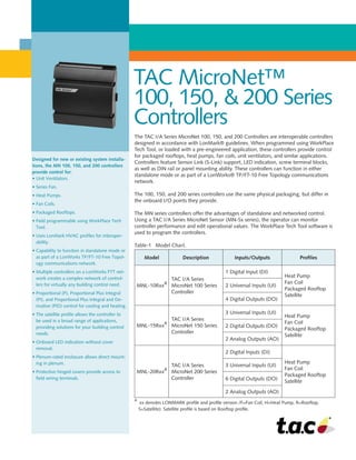
- 1. • • TAC MicroNet™ 100, 150, 200 Series Controllers The TAC I/A Series MicroNet 100, 150, and 200 Controllers are interoperable controllers designed in accordance with LonMark® guidelines. When programmed using WorkPlace Tech Tool, or loaded with a pre-engineered application, these controllers provide control for packaged rooftops, heat pumps, fan coils, unit ventilators, and similar applications. Controllers feature Sensor Link (S-Link) support, LED indication, screw terminal blocks, as well as DIN rail or panel mounting ability. These controllers can function in either standalone mode or as part of a LonWorks® TP/FT-10 Free Topology communications network. The 100, 150, and 200 series controllers use the same physical packaging, but differ in the onboard I/O points they provide. The MN series controllers offer the advantages of standalone and networked control. Using a TAC I/A Series MicroNet Sensor (MN-Sx series), the operator can monitor controller performance and edit operational values. The WorkPlace Tech Tool software is used to program the controllers. Table-1 Model Chart. Model Description Inputs/Outputs Profiles MNL-10Rxx a TAC I/A Series MicroNet 100 Series Controller 1 Digital Input (DI) Heat Pump Fan Coil Packaged Rooftop Satellite 2 Universal Inputs (UI) 4 Digital Outputs (DO) MNL-15Rxx a TAC I/A Series MicroNet 150 Series Controller 3 Universal Inputs (UI) Heat Pump Fan Coil Packaged Rooftop Satellite 2 Digital Outputs (DO) 2 Analog Outputs (AO) MNL-20Rxx a TAC I/A Series MicroNet 200 Series Controller 2 Digital Inputs (DI) Heat Pump Fan Coil Packaged Rooftop Satellite 3 Universal Inputs (UI) 6 Digital Outputs (DO) 2 Analog Outputs (AO) a xx denotes LONMARK profile and profile version /F=Fan Coil, H=Heat Pump, R=Rooftop, S=Satellite). Satellite profile is based on Rooftop profile. Designed for new or existing system installa- tions, the MN 100, 150, and 200 controllers provide control for: • Unit Ventilators. • Series Fan. • Heat Pumps. • Fan Coils. • Packaged Rooftops. • Field programmable using WorkPlace Tech Tool. • Uses LonMark HVAC profiles for interoper- ability. • Capability to function in standalone mode or as part of a LonWorks TP/FT-10 Free Topol- ogy communications network. • Multiple controllers on a LonWorks FTT net- work creates a complex network of control- lers for virtually any building control need. • Proportional (P), Proportional Plus Integral (PI), and Proportional Plus Integral and De- rivative (PID) control for cooling and heating. • The satellite profile allows the controller to be used in a broad range of applications, providing solutions for your building control needs. • Onboard LED indication without cover removal. • Plenum-rated enclosure allows direct mount- ing in plenum. • Protective hinged covers provide access to field wiring terminals.
- 2. Table-2 Inputs from MN-Sx TAC I/A Series MicroNet Sensor. Inputs Description MN-Sx Sensor Space Temperature 32 to 122 °F (0 to 50 °C) MN-S1, MN-S1HT, MN-S2, MN-S2HT, MN-S3, MN-S3HT, MN-S4, MN-S4HT, MN-S4-FCS, MN-S4HT-FCS, MN-S5 and MN-S5HT Space Humidity 5 to 95% RH, Non-condensing MN-S1HT, MN-S2HT, MN-S3HT, MN-S4HT, MN-S4HT-FCS, and MN-S5HT Adjustable Setpoint 40 to 95 °F (4 to 35°C) MN-S3, MN-S3HT, MN-S4, MN-S4HT, MN-S4-FCS, MN-S4HT-FCS, MN-S5, and MN-S5HT Override Pushbut- ton For standalone occupancy con- trol or remote status monitoring of local status condition. MN-S2, MN-S2HT, MN-S3, MN-S3HT, MN-S4, MN-S4HT, MN-S5, and MN-S5HT Fan Operation and Speed Fan mode selection: On, Speed (Low/Medium/High), or Auto. MN-S4, MN-S4HT, MN-S4-FCS, MN-S4HT-FCS, MN-S5, and MN-S5HT System Mode System mode selection: Heat, Cool, Off, or Auto. MN-S4, MN-S4HT, MN-S5, and MN-S5HT Emergency Heat Emergency heat mode selection: Enable or Disable MN-S5 and MN-S5HT Communications LonWorks Networks A LonWorks communications network uses an TP/FT-10 Free Topology configuration. Controllers on a LonWorks network can communicate with each other in a peer-to- peer fashion. A LonWorks network has a communications speed of 78k baud, using unshielded, twisted-pair cabling, with connections that are not polarity sensitive. S-Link The Sensor Link (S-Link) communications wiring provides power and a communica- tion interface for an MN-Sx TAC I/A Series MicroNet sensor. The various MN-Sx sensors can provide room temperature, room humidity, setpoint adjustment, and oc- cupancy override. This connection uses two-wire, unshielded cable and is not polarity sensitive. Maximum wire length allowed between a controller and a TAC I/A Series MicroNet Sensor is 200 ft (61 m). 2 Software Capabilities • Allows design of a complete custom applica- tion for each controller. • Conforms to the LonMark guidelines. • WorkPlace Tech Tool is capable of reconfigur- ing and editing application configuration data. • HVAC interoperability achieved through use of LonMark HVAC profiles. • All controllers are field programmable, but controllers with satellite profiles are espe- cially suited for a broad range of applications, providing solutions for your building control needs.
- 3. Dimensions 4-5/16 H x 4-3/8 W x 2 D in (109 x 111 x 51 mm). Enclosure Conforms to NEMA-1 requirements. Meets UL94-5V flammability for ple- num application use. Conduit Knockouts Not applicable. Order optional MicroNet Enclosure, MNA-FLO-1, if wiring to flex- ible conduit is desired. Power Supply Input 20.4 to 30 Vac, 50/60 Hz. Maximum Power Consumption 15 VA @ 24 Vac, 50/60 Hz, excluding relay output power. Surge Immunity Compliance IEEE C62.41 (IEEE-587, Category A B). Agency Listings FCC Class B. UL UL-916 (File # E71385 Category PAZX). UL Listed to Canadian Safety Standards (CAN/CSA C22.2). European Community – EMC Directive 89/336/EEC EN61326 Mounting 35 mm DIN rail or panel. Ambient Limits Operating Temperature -40 to 140 °F (-40 to 60 °C). Shipping and Storage Temperature -40 to 160 °F (-40 to 71 °C) Humidity 5 to 95% RH, non-condensing. Wiring Terminals Screw terminals. Each terminal accepts one AWG #16 to #24 (1.31 to 0.205 mm2 maximum) wire. Digital Inputs (MN 100 and MN 200 only) Dry Con- tact. Detection of closed switch requires less than 300 ohm. Detection of open switch requires more than 100K ohm. Digital Outputs Current Ratings 24 VA at 24 Vac, pilot duty. Universal Input 1K ohm Balco Input -40 to 250 °F (-40 to 121°C) range. TSMN-81011, TS-8000 Series or equivalent. 1K ohm Platinum Input -40 to 240 °F (-40 to 116 °C) range. TSMN-58011, TS-5800 Series or equivalent. 1k Resistance 0 to 1.5k ohms. 10K ohm Thermistor w/ 11K ohm Shunt Resistor -40 to 250 °F (-40 to 121 °C) range. TSMN-57011-850, TS-5700-850 Series or equivalent. 10k Resistance 0 to 10.5k ohms. Voltage 0 to 5 Vdc. Current 0 to 20 mA requires an external 250 ohm shunt resistor. Digital Input Dry Contact. Detection of closed switch requires less than 300 ohms. Detection of open switch requires more than 1.5K ohms. Analog Outputs (MN 150 and MN 200 only). Current 0 to 20 mA. (Output load from 80 to 550 ohms). SPECIFICATIONS 3
- 4. Copyright © 2006, TAC All brand names, trademarks and registered trademarks are the property of their respective owners. Information contained within this document is subject to change without notice. All rights reserved. F-26291-6 TAC 1354 Clifford Avenue PO Box 2940 Loves Park, IL 61132-2940 www.tac.com LONWORKS Network Desktop PC or Notebook PC with WorkPlace Tech Tool Software 3 1 2 5 PDA MNL-CIM TAC MicroNet Controller Interface Module UNC Controller Router (if required) 6 4 4 MN 100, MN 150, or MN 200 Controller MN 110 or MN 130 Controller DO1 24VAC DO2 DO3 24VAC DO4 Power: 24VAC, 50/60Hz, Class 2, 8.5VA + DO1-DO4 loads. Ambient Temp: -40°C to +60°C UI: 5VDC Max, Class 2. S-LK: 16VDC Max, Class 2. DO1-DO4: 24VAC, 0.4A Max Total Load. DO5: 250VAC, 3A Max, COS f = 0.4. DO5 C5 GND 0V 24VAC UI3 COM 0V UI2 COM 0V UI1 S-LK S-LK LON LON MNL-11RF2 S R V C R E C V X M I T J1 I/A Series 934G E9429 N2223 SRVC CAUTION RI SK OF ELECTRI CAL SHOCK OR FI RE. DO NOT I NTERCONNECT SEPARATE CLASS 2 CI RCUI TS. DI SCONNECT POWER BEFORE S ERVI CI NG. DECONNECTER AVAN T E NTRETEN. This device conforms with Part 15 of the FCC Rules. Operation is subject to the following two conditions: (1) This device may not cause harmful interference, and (2) This device must accept any interference received, including interference that may cause undesired operation. This Class B digital apparatus meets all requirements of the Canadian Interference-Causing Equipment Regulations. Temperature indicating and Regulating Equipment TAC MicroNet Sensor (MN-S5 Shown) MN 80 0 I/A Series® MN 800 Controller MNL-V1RVx or MNL-V2RVx Controller MNL-V3RVx or MN 50 Controller AO SW 24H 3 SW 24H 2 SW 24H 1 24H 24G GN D UI DI S-L K/C OM S-L K LO N LO N TAC MicroNet Sensor (MN-S3 Shown) LONWORKS Network Ethernet Desktop PC with TAC I/A Series Enterprise Server 3 1 A PC can be connected to the LONWORKS TP/FT-10 Network, either directly or through the LONWORKS network jack of a LONWORKS controller or MN-Sxxx Wall Sensor. The PC must have an Echelon® LonTalk® adapter card. 2 Programming any of the TAC I/A Series controllers, or the TAC I/A Series MN 800 controller, requires WorkPlace Tech Tool. 3 This controller is not suitable for exposed mounting on a wall or panel, or in any other easily accessible place due to the possibility of personal contact with the high-voltage terminals. It must be mounted inside a suitable grounded metal enclosure. 4 MicroNet Sensors can be connected to any MN controller. 5 A PDA running the Pocket TAC I/A interface software may be used to communicate with TAC MicroNet I/A Series controllers. 6 When routers are used, WP Tech is able to communicate through them to any of the TAC I/A Series devices on the network. Router (if required) 6 4 MN 80 0 I/A Series® MN 800 Controller 4 TAC MicroNet Sensor (MN-S3 Shown) MNL-V3RVx or MN 50 Controller AO SW 24H 3 SW 24H 2 SW 24H 1 24H 24G GN D UI CO M DI S-L K/C OM S-L K LO N LO N OP EN 24G CLO SE 24G AO MN 110 or MN 130 Controller DO1 24VAC DO2 DO3 24VAC DO4 Power: 24VAC, 50/60Hz, Class 2, 8.5VA + DO1-DO4 loads. Ambient Temp: -40°C to +60°C UI: 5VDC Max, Class 2. S-LK: 16VDC Max, Class 2. DO1-DO4: 24VAC, 0.4A Max Total Load. DO5: 250VAC, 3A Max, COS f = 0.4. DO5 C5 GND 0V 24VAC UI3 COM 0V UI2 COM 0V UI1 S-LK S-LK LON LON MNL-11RF2 S R V C R E C V X M I T J1 I/A Series 934G E9429 N2223 SRVC CAUTION RI SK OF ELECTRI CAL SHOCK OR FI RE. DO NOT I NTERCONNECT SEPARATE CLASS 2 CI RCUI TS. DI SCONNECT POWER BEFORE SE RVI CI NG. DECONNECTER AVAN T E NTRETEN. This device conforms with Part 15 of the FCC Rules. Operation is subject to the following two conditions: (1) This device may not cause harmful interference, and (2) This device must accept any interference received, including interference that may cause undesired operation. This Class B digital apparatus meets all requirements of the Canadian Interference-Causing Equipment Regulations. Temperature indicating and Regulating Equipment TAC MicroNet Sensor (MN-S5 Shown) MN 100, MN 150, or MN 200 Controller MNL-V1RVx or MNL-V2RVx Controller UNC Controller Distributed, manufactured, and sold by TAC. I/A Series trademarks are owned by Invensys Systems, Inc. and are used on this product under master license from Invensys. Invensys does not manufacture this product or provide any product warranty or support. For service, support, and warranty infor- mation, contact TAC at 1-888-444-1311. Figure-1 TAC I/A Series MicroNet MN 100, 150, and 200 Series Controller Connectivity.